SOLTEK SL-85LIR3 User manual

5
Chapter 1 Specification
DVO Card Insert a DVO/TV Out card
to AGP slot for DVO /TV
Out Display.
(AGP card will not boot
system)
DVI
Connector
RTL8101L
PCI 1
PCI 2
ALC
101
Li
Battery
BIOS
IT8712F
DVO
LPT1
COM1
VGA
USB1 (underside)
DIMM1
Main Power
IDE2
IDE1
FD1
+12V Power
USB2
1
FAN1
FAN2
1
J1
1
JKB1
1
JBAT1
1
JCLK2
JCLK1
CD1
1
PS/2 K/B (underside)
PS/2 Mouse
(on top)
DDR 400/333/266/200MHz
RT1
mPGA478B
i845GL
Intel
ICH4
Intel
1
WOL1
DIMM2
JAUD1
RJ45
(ontop)
Linein
(ontop)
USB3 (underside)
USB2 (middle)
(ontop)
USB0
HDD IR PWR
1
20
SPK RST +
-
+
-
PWLED
NJ1
LED
Jp1
11
1
LPC I/O
10
9
AC' 97
Codec
System Fan
Connector
Thermal
Connector
CPU Fan
Connector
1-1 Mainboard Layout and Components Setup
Chapter 1 Specification
Front Audio
Connector
CD-ROM Audio
Connector
Line Out (middle)
Mic (underside)
LAN Controller
(only for LIR3-L)
J1 for LAN
Controller Select
(only for LIR3-L)
1
10
First USB Port Pin-Assignment for Front USB
Second USB Port Pin-Assignment for Front USB
+5V
Red White
black
+5V
Red
Green
GreenWhite
black
GND
GND
D1- D1+
D2- D2+
2
Wake-On-LAN Connector
Connect the Wake On LAN
signal from LAN card to WOL1
WOL1:
Ring
GND
+5V
Standby
VGA
Connector
Analog
Monitor
RJ45 connector
LAN Controller
J1 For
85LIR3-L
only
}

6
85LIR3 / 85LIR3-L
CPU
North Bridge
South Bridge
BIOS
Memory
I/O Chip
AGP interface
Audio
IDE Interface
Networking
PCI Slots
I/O Connectors
VGA Display
Other Features
Socket 478B for Intel P4 CPU
Intel 845GL, supporting *800/533/400MHz FSB
Intel ICH4
AMI BIOS
Supporting DDR *400/333/266/200 DRAM, up to
2GB in two DDR DIMM slots
IT8712F
AGP4X mode only
AC’97 Audio V2.2 compliant, 2-channel audio
2 UATA 33/66/100 IDE ports
Fast Ethernet Controller, 1 RJ45 (for 85LIR3-L)
2 PCI Master slots on board
6 USB ports (V2.0), 1 FDD port, 1 COM port,
1 LPT, 1 IrDA, 1 PS/2 K/B, 1 PS/2 Mouse,
1 VGA connector on board for CRT VGA display
Keyboard/ Mouse Power On/Wake Up
ATX 2.03 Power Supply;
Micro-ATX form factor
SL-85LIR3 / 85LIR3-L Specifications and Features
1-2 Mainboard Specification Table
85LIR3
No
LAN Controller
on board
Optional
Features
Models 85LIR3-L
Yes
* Note: FSB 800/533MHz and DDR400/333 are supported by chipset
overclocking.

7
Chapter 1 Specification
mPGA478B
Pin 1
1. First pull sideways the lever of
Socket 478, and then turn it up
900so as to raise the upper layer
of the socket from the lower
platform.
3. Make sure that all CPU pins have
completely entered the socket
and then lower down the lever
to lock up CPU to socket.
2. Configure Pin 1 of CPU to Pin 1
of the Socket, just as the way
shown in the diagram on the
right. Adjust the position of CPU
until you can feel all CPU pins
get into the socket with ease.
mPGA478B
Intel Pentium4
mPGA478B
Intel Pentium 4
Pin 1
Pin 1
1-3 Pentium 4 CPU Installation
This mainboard is built with CPU Socket 478 (with 478 pins) supporting
the Intel Pentium 4 CPU:
• Follow the steps described in this section to install the 478-pin Pentium
4 CPU into the on board Socket 478.
• After installation of Pentium 4 CPU, you must also install the specific
Pentium 4 CPU fan designed in tandom with this CPU. This CPU Fan
installation is described in the next section.

8
85LIR3 / 85LIR3-L
1-4 Pentium 4 CPU Fan Installation
Connect Fan Connector to CPU FAN connector
Press down 4 corners to lock fan to fanbase
1-5 ATX V 2.03 Power Supply Installation
RTL8101L
PCI 1
PCI 2
ALC
101
Li
Battery
BIOS
IT8712F
DVO
LPT1
COM1
VGA
USB1 (underside)
DIMM1
Main Power
IDE2
IDE1
FD1
+12V Power
USB2
1
FAN1
FAN2
1
J1
1
JKB1
1
JBAT1
1
JCLK2
JCLK1
CD1
1
PS/2 K/B (underside)
PS/2 Mouse
(on top)
DDR 400/333/266/200MHz
RT1
mPGA478B
i845GL
Intel
ICH4
Intel
1
WOL1
DIMM2
JAUD1
RJ45
(on top)
Linein
(on top)
USB3 (underside)
USB2 (middle)
(ontop)
USB0
HDD IR PWR
1
20
SPK RST
+
-
+
-
PWLED
NJ1
LED
Jp1
11
1
LPC I/O
10
9
AC' 97
Codec
System Fan
Connector
Thermal
Connector
CPU Fan
Connector
Main Power
Connector
+12V
5SB
PWR OK
GND
GND
GND
GND
GND
GND
+5V
+5V
-5V
+5V
+5V
+3.3V
+3.3V +3.3V
PS ON#
Pin1 Pin11
-12V
GND
+12V Power Connector
+12V
+12V
GND
GND
12
34
Warning: Both the Main Power
Connector and the +12V Power
Connector should be connected
to Power Supply; otherwise, the
system may either not start or be
damaged.

9
Chapter 1 Specification
1-6 Jumper Settings
The following diagrams show the locations and settings of jumper blocks
on the mainboard.
RTL8101L
PCI 1
PCI 2
ALC
101
Li
Battery
BIOS
IT8712F
DVO
LPT1
COM1
VGA
USB1 (underside)
DIMM1
Main Power
IDE2
IDE1
FD1
+12V Power
USB2
1
FAN1
FAN2
1
J1
1
JKB1
1
JBAT1
1
JCLK2
JCLK1
CD1
1
PS/2 K/B (underside)
PS/2 Mouse
(on top)
DDR 400/333/266/200MHz
RT1
mPGA478B
i845GL
Intel
ICH4
Intel
1
WOL1
DIMM2
JAUD1
RJ45
(on top)
Linein
(ontop)
USB3 (underside)
USB2 (middle)
(ontop)
USB0
HDD IR PWR
1
20
SPK RST
+
-
+
-
PWLED
NJ1
LED
Jp1
11
1
LPC I/O
10
9
AC' 97
Codec
System Fan
Connector
Thermal
Connector
CPU Fan
Connector
JBAT1
Clear CMOS
1-2 closed
(default)
To hold data
2-3 closed
To clear CMOS
1
1
(85LIR3-L only)
J1
1-2 closed
2-3 closed
LAN Controller Select
(default)
Enabled
Disabled
1
1
(default)
JCLK1&JCLK2: CPU Frequency Select
CPU
Auto-
Detection
100MHz 133MHz 200MHz
(FSB533)
1 1
JCLK2
1 1
JCLK1
JCLK2
JCLK1
11
JCLK2
JCLK1
11
JCLK2
JCLK1
Keyboard/Mouse
Power On / Wake Up
JKB1:
1-2 closed (default)
2-3 closed
Enabled
1
1
Disabled

10
85LIR3 / 85LIR3-L
RTL8101L
PCI 1
PCI 2
ALC
101
Li
Battery
BIOS
IT8712F
DVO
LPT1
COM1
VGA
USB1 (underside)
DIMM1
Main Power
IDE2
IDE1
FD1
+12V Power
USB2
1
FAN1
FAN2
1
J1
1
JKB1
1
JBAT1
1
JCLK2
JCLK1
CD1
1
PS/2 K/B (underside)
PS/2 Mouse
(on top)
DDR 400/333/266/200MHz
RT1
mPGA478B
i845GL
Intel
ICH4
Intel
1
WOL1
DIMM2
JAUD1
RJ45
(ontop)
Linein
(ontop)
USB3 (underside)
USB2 (middle)
(ontop)
USB0
HDD IR PWR
1
20
SPK RST
+
-
+
-
PWLED
NJ1
LED
Jp1
11
1
LPC I/O
10
9
AC' 97
Codec
System Fan
Connector
Thermal
Connector
CPU Fan
Connector
1-7.1 Front Audio Connector
This Mainboard is designed with a Front
Panel Audio connector “JAUD1” which
provides connection to your chassis.
1. When JAUD1 is set to 5-6 closed and
9-10 closed, this default setting
disables this connector and leaves the
Back Panel Audio enabled.
2. To use this Front Panel Audio
Connector, please open all pins of
JAUD1 and connect it to your chassis.
1-7 Other Connectors Setup
2. Connector Jp1: A thermal cable is needed
to connect Jp1 to on-board devices such
as HDD, Graphics card etc., so as to
detect the temperature generated therein.
Please connect the end (a) of the thermal
cable to Jp1, and tape another end (b) of
thermal cable on to the device which you
want to monitor. After you have finished
the thermal cable installation, you will see
the detected temperature in BIOS setup
or Hardware Monitor utility.
RT1 is mounted with Ther-
mal Resistor by default for
detecting the external CPU
temperature.
To Devices
To Jp1
Thermal Cable
RT1
Jp1
1. Resistor RT1: A thermal resistor is
mounted by default to connector RT1 so
as to detect the external CPU temperature
. What RT1 does is to transmit the thermal
signal to Hardware Monitor.
1-7.2 Thermal Resistor and Connector
(Optional)
JAUD1: Front Panel Audio Connector
Pin 1 Mic In
Pin 3 Mic VREF
Pin 5 FPOUT R
Pin 7 (Key)
Pin 9 FPOUT L
Pin 2 Aud GND
Pin 4 Aud Vcc
Pin 6 RET R
Pin 10 RET L

11
Chapter 1 Specification
(1) Power Switch Connector:
Connection:Connected to a momentary button or switch.
(2) IR Connector (Infrared Connector):
Connection: Connected to Connector IR on board.
(3) HDD LED Connector:
Connection: Connected to HDD LED.
(4) Power LED Connector:
Connection: Connected to System Power LED.
(5) Reset Switch Connector:
Connection: Connected to case-mounted “Reset Switch”.
(6) Speaker Connector:
Connection: Connected to the case-mounted Speaker.
RTL8101L
PCI 1
PCI 2
ALC
101
Li
Battery
BIOS
IT8712F
DVO
LPT1
COM1
VGA
USB1 (underside)
DIMM1
Main Power
IDE2
IDE1
FD1
+12V Power
USB2
1
FAN1
FAN2
1
J1
1
JKB1
1
JBAT1
1
JCLK2
JCLK1
CD1
1
PS/2 K/B (underside)
PS/2 Mouse
(on top)
DDR 400/333/266/200MHz
RT1
mPGA478B
i845GL
Intel
ICH4
Intel
1
WOL1
DIMM2
JAUD1
RJ45
(ontop)
Linein
(ontop)
USB3 (underside)
USB2 (middle)
(ontop)
USB0
HDD IR PWR
1
20
SPK RST
+
-
+
-
PWLED
NJ1
LED
Jp1
11
1
LPC I/O
10
9
AC' 97
Codec
System Fan
Connector
Thermal
Connector
CPU Fan
Connector
(1)Power Switch PLED-
NC
PLED+
RSTGND
RST1
SP1
NC
SP3
SPVCC
PWRBT#
PWRBT
IR_VCC
NC
IRRX
IRGND
IRTX
HDLED-
HDLED+
(2)Infrared(IR)
(3)HDD LED
Power LED (4)
Reset Switch (5)
Speaker (6)
1-7.3 Complex Header (Front Panel Connectors)

12
85LIR3 / 85LIR3-L
2-1 To Open up the Support CD
1. Please put the Support CD enclosed in your mainboard package into
the CD-ROM drive. In a few seconds, the Main Menu will automatic-
ally appear, displaying the contents to be installed for this series:
Chapter 2 Software Setup
The LAN driver contained in the Support CD is not included in the
Autorun Menu. To install RTL8101L LAN driver on Windows 9X, please
follow the steps shown below:
1. On the “Start” screen of your system, please click to the following
path:
\My Computer\properties\Device manager
2. In the “Device manager” screen, you can see the item “ PCI Ethernet
Controller” with a yellow question mark on its left side, which indicates
that the LAN controller is already detected by system but the driver
for this on-board RTL8101L Ethernet Controller is not installed yet.
Please point to this item with your mouse and double click on it (or
click the “Properties” button).
2-2.1 RTL8101L LAN driver on Windows 9X
`äáÅâ=eÉêÉ
3. Instantly, the “PCI Ethernet
Controller Properties“ screen
shows up. Please click the
“General” bar to continue.
4. In the “General” screen, click
“reinstall Driver” button to
continue. Please note that the
status of “Device Usage” should
stay at “Exists in all hardware
profiles”.
2-2 To Install LAN Drivers (for 85LIR3-L only)

13
Chapter 2 Software Setup
2-2.2 RTL8101L LAN driver on Windows ME / 2000 / XP
1. When you newly install Windows ME, Windows 2000 or Windows
XP, the system will detect the LAN Controller on board and configure
it automatically into system. Therefore, users need not bother to install
the LAN controller into these operating systems.
2. To verify the existence of RTL8101L Controller and Driver, please
enter the “Control Panel” of your system and click “Network” to open
the “Configuration” screen. You can then see the “Realtek8139 (A/
B/C) PCI Fast Ethernet Adapter” is already installed in your system.
5. In the “Update device Driver Wizard” screen, click “Next” to continue
until you see a dialog box asking you to “Specify a location” for the
driver. You should now insert the Support CD into your CD-ROM.
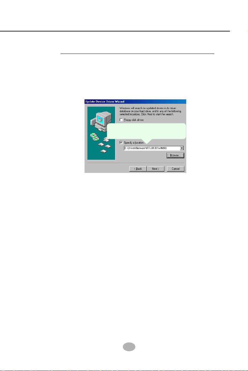
6. As illustrated in the picture below, check the item “Specify a location”
and click the “Browse” button to find out the correct path for the
driver. Supposing your CD-ROM drive is Drive E, please type:
E:\Driver\Network\RTL8139\Win98 into the blank bar. (Please note
that both RTL8101L and RTL8139C controllers are supported by
Driver RTL8139. ) Then click the “Next” button to continue.
Enter the correct path for the
location of LAN driver
7. The Update Device Driver Wizard will then go on installing the driver,
until the “Insert Disk” dialog box shows up. Please withdraw your
Support CD and insert the Windows 98SE CD-ROM into the CD-
ROM drive for updating system and click “OK” to continue.
8. The Update Device Driver Wizard will then proceed to update the
system with the LAN driver. When the “Finish” screen shows up,
click “Finish” to continue.
9. Final Dialog box will appear to remind you that you must restart your
computer to finish updating the new hardware. Please click “Yes” to
restart system and finish the LAN driver installation.

14
85LIR3 / 85LIR3-L
2-3 To Install USB 2.0 Driver for Windows 2000/XP
USB V2.0 with its 480Mb/s transfer rate supports operating system
Windows 2000 and Windows XP via the Windows 2000 and Windows
XP Service Pack. For archieving Intel USB 2.0 support, users should
install the latest Service Pack for Windows 2000 or Windows XP. (intel
USB 2.0 does not support Windows 9X/ME.)
1. After installation of Intel Chipset software installation Utility in Windows
2000 or Windows XP, start to install the latest Service Pack version
into the operating system. The installation of the latest Service Pack
will support USB2.0 in Windows 2000 or Windows XP now.(The latest
Service Pack can be found in Microsoft Web Site.)
2. To verify USB2.0 installation, please enter “Device Manager” of “My
Computer”. On the “Device Manager” screen, you should be able to
see the item “Standard Enhanced PCI to USB Host Controller”,
verifying USB2.0 Driver is installed successfully.

15
Chapter 3 BIOS Setup
Chapter 3 AMI BIOS Setup
• “AMIFLASH.EXE” is a Flash EPROM Programming utility that up-
dates the BIOS by uploading a new BIOS file to the programmable
flash ROM on the mainboard. This program only works in DOS
environment, the utility can not be executed in Windows 95/98,
ME, NT, 2000 or Windows XP environment.
• Please follow the steps below for updating the sys-
tem BIOS:
Step 1. Please visit the board maker’s website, download latest BIOS
file and AMI update utility. The file name of AMI update utility will be
“AMIXXX.EXE” of which “ XXX ” stands for the version number of the
file. The BIOS file format will be *.ROM, of which “ * ” stands for the
specific BIOS file name.
Step 2. Create a bootable diskette. Then copy the BIOS file and AMI
flash utility “AMIXXX.EXE” into the diskette.
Step 3. Insert the diskette into drive A, boot your system from the
diskette.
3-1 To Update BIOS
Step 4. Under “ A “ prompt, type “ AMIXXX.EXE *.ROM “ and then
press <Enter> to run BIOS update program. Please note that there
should be a space between AMIXXX.EXE and *.ROM. (*.ROM depends
on your mainboard model and version code. Instead of typing “*”, you
should type the specific file name for your specific mainboard).
Step 5. When the message “Flash ROM Update Completed - Pass.”
appears, please restart your system.
Step 6. You will see a message “CMOS Memory Size Wrong” during
booting the system. Press <Del> or <F1> to run CMOS setup utility,
then reload “LOAD SETUP DEFAULTS” or “Load Optimal Defaults”
and save this change.

16
85LIR3 / 85LIR3-L
3-2 BIOS SETUP by CMOS Setup Utility
• Standard CMOS Features(Times, Date, Hard Disk Type etc.)
• Advanced BIOS Features (Virus Protection, Boot Sequence etc.)
• Advanced Chipset Features (AT Clock, DRAM Timing etc.)
• Power Management Features (Sleep Timer, Suspend Timer etc.)
• PNP/PCI Configurations (IRQ Settings, Latency Timers etc.)
• Integrated Peripherals (Onboard I/O, IRQ, DMA Assign. etc.)
• Hardware Monitor Status (CPU/System Temp., Fan speed etc.)
• Frequency/Voltage (CPU clock, Voltage of CPU, DIMM, AGP etc.)
1. Power on your system.
2. At the initial screen, enter CMOS Setup Utility by pressing < Del >
key before POST(Power on Self Test) is complete and the main
program screen will appear as follows.
3. Use the arrow keys on your keyboard to select an option, and press
<Enter>. Modify the system parameters to reflect the options installed
in your system.
4. You may return to the Main Menu anytime by pressing <Esc>.
5. In the Main Menu, “Save Changes and Exit” saves your changes and
reboots the system, and “Discard Changes and Exit” ignores your
changes and exits the program.
AMIBIOS NEW SETUP UTILITY - VERSION 3.31a
Standard CMOS Features
Advanced BIOS Features
Advanced Chipset Features
Power Management Features
PNP/PCI Configurations
Integrated Peripherals
Hardware Monitor Status
Frequency/Voltage Control
Set Supervisor Password
Load Optimal Defaults
Save & Exit Setup
Exit Without Saving
Set Time, Date, Hard Disk Type ...
F1: Help : Select Item +/- : Change Values F9: Setup
Defaults Esc: Exit : Select Menu Enter: Select Sub-Menu
F10: Save and Exit

SL-85LIR3 / 85LIR3-L Quick Installation Guide
Réglage des cavaliers Jumper-Einstellungen Configuración de Jumper Configuração
de Jumper 跳線設定跳線設定
跳線設定跳線設定
跳線設定
ジャンパーセッティングジャンパーセッティング
ジャンパーセッティング
점퍼점퍼
점퍼점퍼
점퍼
세팅세팅
세팅세팅
세팅
○○○○○○○○○○○○○○○○○○○○○○○○○○○○○○○○○○○○○○○○○○○○○○○○○○○○
Sélection du contrôleur LAN
J1 (uniquement sur la SL-85LIR3-L)
1-2=LAN activé (par défaut)
2-3=LAN désactivé
Selección del LAN Controller
J1 (SL-85LIR3-L solamente)
1-2=LAN Activado (por defecto)
2-3=LAN Desactivado
Seleção de Controladora de Rede
J1 (somente SL-85LIR3-L)
1-2=Habilitar Rede (padrão)
2-3=Desabilitar Rede
LAN Controller Ausgewählt
J1 (Nur SL-85LIR3-L)
1-2=Lan zur verfügung (Standard)
2-3=Lan nicht verfügbar
LL
LL
LAA
AA
ANN
NN
N
裝裝
裝裝
裝置置
置置
置設設
設設
設定定
定定
定
J1 (J1 (
J1 (J1 (
J1 (僅供給僅供給
僅供給僅供給
僅供給 SL-85LIR3-L)SL-85LIR3-L)
SL-85LIR3-L)SL-85LIR3-L)
SL-85LIR3-L)
1-2=1-2=
1-2=1-2=
1-2= 開啟開啟
開啟開啟
開啟 LAN LAN
LAN LAN
LAN 功能功能
功能功能
功能((
((
(預設值預設值
預設值預設值
預設值))
))
)
2-3=2-3=
2-3=2-3=
2-3= 關閉關閉
關閉關閉
關閉 LAN LAN
LAN LAN
LAN 功能功能
功能功能
功能
LL
LL
LAA
AA
ANN
NN
N
콘콘
콘콘
콘트트
트트
트롤롤
롤롤
롤러러
러러
러
선선
선선
선택택
택택
택
J1 (SL-85LIR3-L J1 (SL-85LIR3-L
J1 (SL-85LIR3-L 모델만모델만
모델만모델만
모델만
해당해당
해당해당
해당))
))
)
1-2=LAN 1-2=LAN
1-2=LAN 1-2=LAN
1-2=LAN 사용사용
사용사용
사용 ( (
( (
(기본값기본값
기본값기본값
기본값))
))
)
2-3=LAN 2-3=LAN
2-3=LAN 2-3=LAN
2-3=LAN 사용사용
사용사용
사용
안함안함
안함안함
안함
LL
LL
LAA
AA
ANN
NN
N装装
装装
装置置
置置
置のの
のの
の設設
設設
設定定
定定
定
J1 J1
J1 J1
J1 ((
((
(SL-85LIR3-LSL-85LIR3-L
SL-85LIR3-LSL-85LIR3-L
SL-85LIR3-L のみ搭載)のみ搭載)
のみ搭載)のみ搭載)
のみ搭載)
1-2=LAN1-2=LAN
1-2=LAN1-2=LAN
1-2=LAN を使用する場合を使用する場合
を使用する場合を使用する場合
を使用する場合
((
((
(デデ
デデ
デフフ
フフ
フォォ
ォォ
ォ
トト
トト
ト))
))
)
2-3=LAN2-3=LAN
2-3=LAN2-3=LAN
2-3=LAN を使用しない場合を使用しない場合
を使用しない場合を使用しない場合
を使用しない場合
J1 LAN Controller Select (SL-85LIR3-L only)
1
1-2
(default)
1
2-3
1

○○○○○○○○○○○○○○○○○○○○○○○○○○○○○○○○○○○○○○○○○○○○○○○○○○○○
JCLK1 & JCLK2 CPU Clock Select
CC
CC
CPP
PP
PUU
UU
Uクク
クク
クロロ
ロロ
ロッッ
ッッ
ックク
クク
ク設設
設設
設定定
定定
定
JCLK1 & JCLK2JCLK1 & JCLK2
JCLK1 & JCLK2
はは
はは
はCPUCPU
CPUCPU
CPU 自動検出設定用自動検出設定用
自動検出設定用自動検出設定用
自動検出設定用((
((
(デデ
デデ
デフフ
フフ
フォォ
ォォ
ォ
トト
トト
ト))
))
)
はは
はは
は100MHz100MHz
100MHz100MHz
100MHz 使用時の設定使用時の設定
使用時の設定使用時の設定
使用時の設定
はは
はは
は133MHz133MHz
133MHz133MHz
133MHz 使用時の設定使用時の設定
使用時の設定使用時の設定
使用時の設定
はは
はは
は200MHz200MHz
200MHz200MHz
200MHz 使用時の設定使用時の設定
使用時の設定使用時の設定
使用時の設定
Sélection de la fréquence du CPU
JCLK1 & JCLK2
Autodétection du CPU (par défaut)
Pour une fréquence CPU de 100MHz
Pour une fréquence CPU de 133MHz
Pour une fréquence CPU de 200MHz
Seleção de Clock do CPU
JCLK1 & JCLK2
Detecção automática do CPU (Padão)
Para 100MHz de Clock do CPU
Para 133MHz de Clock do CPU
Para 200MHz de Clock do CPU
CC
CC
CPP
PP
PUU
UU
U클클
클클
클럭럭
럭럭
럭
선선
선선
선택택
택택
택법법
법법
법
JCLK1 JCLK2JCLK1 JCLK2
JCLK1 JCLK2
CPU CPU
CPU CPU
CPU
클락클락
클락클락
클락
자동자동
자동자동
자동
선택선택
선택선택
선택 ( (
( (
(기본값기본값
기본값기본값
기본값))
))
)
100MHz CPU 100MHz CPU
100MHz CPU 클럭클럭
클럭클럭
클럭
선택선택
선택선택
선택
133MHz CPU 133MHz CPU
133MHz CPU 클럭클럭
클럭클럭
클럭
선택선택
선택선택
선택
200MHz CPU 200MHz CPU
200MHz CPU 클럭클럭
클럭클럭
클럭
선택선택
선택선택
선택
CPU Clock Einstellungen
JCLK1 & JCLK2
CPU Autodetect (Standard)
Fur 100MHz CPU Clock
Fur 133MHz CPU Clock
Fur 200MHz CPU Clock
Selección de Clock del CPU
JCLK1 & JCLK2
CPU Autodetect (por defecto)
Para 100MHz CPU Clock
Para 133MHz CPU Clock
Para 200MHz CPU Clock
CC
CC
CPP
PP
PUU
UU
U
頻頻
頻頻
頻率率
率率
率設設
設設
設定定
定定
定
JCLK1 JCLK2JCLK1 JCLK2
JCLK1 JCLK2
CPU CPU
CPU CPU
CPU 自動偵測自動偵測
自動偵測自動偵測
自動偵測 ( (
( (
(預設值)預設值)
預設值)預設值)
預設值)
選擇選擇
選擇選擇
選擇 100MHz CPU 100MHz CPU
100MHz CPU 100MHz CPU
100MHz CPU 頻率頻率
頻率頻率
頻率
選擇選擇
選擇選擇
選擇 133MHz CPU133MHz CPU
133MHz CPU133MHz CPU
133MHz CPU 頻率頻率
頻率頻率
頻率
選擇選擇
選擇選擇
選擇 200MHz CPU200MHz CPU
200MHz CPU200MHz CPU
200MHz CPU 頻率頻率
頻率頻率
頻率
○○○○○○○○○○○○○○○○○○○○○○○○○○○○○○○○○○○○○○○○○○○○○○○○○○○○
Tastatur/ Maus Energie ein /Aufwachen
JKB1
1-2=Deaktiviert (Standard)
2-3=Aktiviert
Ligar no Teclado/Rato de arranque / acordar
JKB1
1-2=Desabilitado (Padrão)
2-3=Habilitado
Allumage / Réveil par Clavier /Souris
JKB1
1-2=Mis hors service (par défaut)
2-3=Activée
鍵鍵
鍵鍵
鍵盤盤
盤盤
盤//
//
/滑滑
滑滑
滑鼠鼠
鼠鼠
鼠
開開
開開
開機機
機機
機//
//
/喚喚
喚喚
喚醒醒
醒醒
醒
功功
功功
功能能
能能
能
JKB1JKB1
JKB1JKB1
JKB1
1-2= 1-2=
1-2= 1-2=
1-2= 關閉功能關閉功能
關閉功能關閉功能
關閉功能 ( (
( (
(預設值預設值
預設值預設值
預設值))
))
)
2-3 = 2-3 =
2-3 = 2-3 =
2-3 = 開啟功能開啟功能
開啟功能開啟功能
開啟功能
Teclado/Ratón de Energía /Wakeup
JKB1
1-2=Desactivado (por defecto)
2-3=Activado
JKB1 KB/Mouse Power on / Wake up
키키
키키
키보보
보보
보드드
드드
드//
//
/마마
마마
마우우
우우
우스스
스스
스
전전
전전
전원원
원원
원--
--
-온온
온온
온//
//
/절절
절절
절전전
전전
전모모
모모
모드드
드드
드에에
에에
에서서
서서
서
제제
제제
제
JKB1JKB1
JKB1JKB1
JKB1
1-2=1-2=
1-2=1-2=
1-2= 사용금지사용금지
사용금지사용금지
사용금지 ( (
( (
(기본값기본값
기본값기본값
기본값))
))
)
2-3=2-3=
2-3=2-3=
2-3= 사용가능사용가능
사용가능사용가능
사용가능
キキ
キキ
キーー
ーー
ーボボ
ボボ
ボーー
ーー
ードド
ドド
ド//
//
/ママ
ママ
マウウ
ウウ
ウスス
スス
ス力力
力力
力のの
のの
の電電
電電
電源源
源源
源をを
をを
を入入
入入
入れれ
れれ
れるる
るる
るここ
ここ
こ
とと
とと
と//
//
/ウウ
ウウ
ウ
クク
クク
クーー
ーー
ーウウ
ウウ
ウププ
ププ
プ
JKB1JKB1
JKB1JKB1
JKB1
1-2=1-2=
1-2=1-2=
1-2= 設定無効にする設定無効にする
設定無効にする設定無効にする
設定無効にする ( (
( (
(デフォ トデフォ ト
デフォ トデフォ ト
デフォ ト))
))
)
2-3=2-3=
2-3=2-3=
2-3= 設定有効設定有効
設定有効設定有効
設定有効
1-2 (default)
1
2-3
1
CMOS Daten löschen
JBAT1
1-2 Daten erhalten (Standard)
2-3 CMOS Daten löschen
CC
CC
CMM
MM
MOO
OO
OSS
SS
S
デデ
デデ
デーー
ーー
ータタ
タタ
タをを
をを
を消消
消消
消却却
却却
却
JBAT1JBAT1
JBAT1JBAT1
JBAT1
1-2 1-2
1-2 1-2
1-2 データを記憶するデータを記憶する
データを記憶するデータを記憶する
データを記憶する
((
((
(デデ
デデ
デフフ
フフ
フォォ
ォォ
ォ
トト
トト
ト))
))
)
2-3 CMOS 2-3 CMOS
2-3 CMOS 2-3 CMOS
2-3 CMOS データを消却データを消却
データを消却データを消却
データを消却
Limpar dados do CMOS
JBAT1
1-2 Reter Dados (Padrão)
2-3 Limpar dados do CMOS
Effacement du CMOS
JBAT1
1-2 Conservation des données (par défaut)
2-3 Effacement du CMOS
CC
CC
CMM
MM
MOO
OO
OSS
SS
S
데데
데데
데이이
이이
이타타
타타
타
삭삭
삭삭
삭제제
제제
제
JBAT1JBAT1
JBAT1JBAT1
JBAT1
1-2 1-2
1-2 1-2
1-2 원래값원래값
원래값원래값
원래값
유지유지
유지유지
유지 ( (
( (
(기본값기본값
기본값기본값
기본값))
))
)
2-3 2-3
2-3 2-3
2-3 현재현재
현재현재
현재 CMOS CMOS
CMOS CMOS
CMOS 데이타데이타
데이타데이타
데이타
삭제삭제
삭제삭제
삭제
清清
清清
清除除
除除
除CC
CC
CMM
MM
MOO
OO
OSS
SS
S功功
功功
功能能
能能
能
JBAT1JBAT1
JBAT1JBAT1
JBAT1
1-2 1-2
1-2 1-2
1-2 記憶資料記憶資料
記憶資料記憶資料
記憶資料 ( (
( (
(預設值預設值
預設值預設值
預設值))
))
)
2-3 2-3
2-3 2-3
2-3 清除清除
清除清除
清除 CMOSCMOS
CMOSCMOS
CMOS 功能功能
功能功能
功能
Borrar el CMOS
JBAT1
1-2 Retener Dados (por defecto)
2-3 Borrar el CMOS
JBAT1 Clear CMOS
2
3
4
1
2
3
4
1
2
3
4
1
2
3
4
1
2
3
4
1
2
3
4
1
2
3
4
4321 1
2
3
4
1-2
(default)
1
2-3
1
CPU Auto-detect
(default)
1
JCLK2 JCLK1
100MHz
1
JCLK2 JCLK1
133MHz
1
JCLK2 JCLK1
1
200MHz
JCLK2 JCLK1
This manual suits for next models
1
Table of contents
Other SOLTEK Motherboard manuals

SOLTEK
SOLTEK 85ERV User manual

SOLTEK
SOLTEK SL-56H5 User manual

SOLTEK
SOLTEK SL-85SD-C User manual

SOLTEK
SOLTEK KT400 User manual

SOLTEK
SOLTEK SL-B8D-F User manual

SOLTEK
SOLTEK 85DRV5 User manual

SOLTEK
SOLTEK 75FRV User manual

SOLTEK
SOLTEK SL-55D5 Use and care manual

SOLTEK
SOLTEK SL-75MIV User manual

SOLTEK
SOLTEK B7A-F User manual

SOLTEK
SOLTEK SL-75KAV User manual

SOLTEK
SOLTEK SL-B5A-FG User manual

SOLTEK
SOLTEK SL-75KAV User manual

SOLTEK
SOLTEK SL-845GLI User manual

SOLTEK
SOLTEK 85ERV2 User manual

SOLTEK
SOLTEK SL-PT880E-R User manual

SOLTEK
SOLTEK KT400-R User manual

SOLTEK
SOLTEK SL-65EP User manual

SOLTEK
SOLTEK SL-65DRV User manual

SOLTEK
SOLTEK KT333A User manual