EVOC EC7-1817LNAR User manual

EC7-1817LNAR
基于 Chief rive 平台(IVY bridge CPU+QM67
PCH)的 MINI-ITX 主板
MINI-ITX motherboard based on Chief
River platform (IVY Bridge CPU+QM67
PCH)
Version: C02

Copyright Notice
Information offered in this manual is believed to be correct at the time of printing, and
is subject to change without prior notice in order to improve reliability, design and
function and does not represent a commitment on the part of the manufacturer. In no
event will the manufacturer be liable for direct, indirect, special, incidental, or
consequential damages arising out of improper installation and/or use, or inability to
use the product or documentation.
This user manual is protected by copyright. No part of this manual may be reproduced,
stored in any retrieval system, or transmitted, in any form or by any means,
mechanical, electronic, photocopied, recorded or otherwise, without the prior written
permission from the manufacturer.
Trademarks
EVOC is a registered trademark of EVOC Intelligent Technology Co., Ltd. Other
product names mentioned herein are used for identification purposes only and may be
trademark and/or registered trademarks of their respective companies.
Please visit our website: http://www.evoc.com for more information,
Or send to the Technical Support Mailbox support@evoc.com or
Customer Service Hotline: 4008809666

Safety Instructions
1. Please read this manual carefully before using the product;
2. Leave the board or card in the antistatic bag until you are ready to use it;
3. Touch a grounded metal object (e.g. for 10 seconds) before removing the board
or card from the anti-static bag;
4. Before installing or removing a board, wear the ESD gloves or ESD wrist strap;
handle the board by its edges only;
5. Before inserting, removing or re-configuring motherboards or expansion cards,
first disconnect the computer and peripherals from their power sources to
prevent electric shock to human bodies or damage to the product;
6. Remember to disconnect the AC power cord from the socket before removing
the board or moving the PC;
7. For PC products, remember to disconnect the computer and peripherals from the
power sources before inserting or removing a board;
8. Before connecting or disconnecting any terminal, peripheral or any device, be
sure the system is powered off and all the power sources are disconnected;
9. After turning off the computer, wait at least 30 seconds before turning it back on

Contents
Chapter 1 Product Introduction.....................................................................................1
Overview ..............................................................................................................1
Mechanical Dimensions, Weight and Environment ..............................................1
Typical Consumption............................................................................................1
Microprocessor .....................................................................................................2
Chipset..................................................................................................................2
System Memory....................................................................................................2
Display Function...................................................................................................2
Network Function .................................................................................................3
Audio Function .....................................................................................................3
Power Feature .......................................................................................................3
Expansion Bus ......................................................................................................4
Watchdog Function ...............................................................................................4
Operating System..................................................................................................4
On-board I/O.........................................................................................................4
Chapter 2 Installation....................................................................................................5
Product Outline.....................................................................................................5
Locations of Connectors .......................................................................................6
Structure................................................................................................................7
Jumper Setting ......................................................................................................8
Install the System Memory ...................................................................................9
Serial Port .............................................................................................................9
LCD Backlight Control Connector .....................................................................10
USB Port.............................................................................................................10
Display Connector ..............................................................................................11
Audio Connector.................................................................................................14

Status Indicating and Control Connector ............................................................14
Power Connector ................................................................................................15
SATA Connector .................................................................................................15
Hot-swap of SATA Hard Disk.............................................................................15
LAN Port ............................................................................................................17
Switch .................................................................................................................18
GPIO Connector .................................................................................................18
Fan Connector.....................................................................................................18
TPM Pin Header .................................................................................................19
Mini PCIe Connector..........................................................................................20
PCIe x4 Slot........................................................................................................21
Install the CPU....................................................................................................21
Install the CPU Fan.............................................................................................22
Chapter 3 BIOS Setup ................................................................................................23
UEFI Overview...................................................................................................23
UEFI Parameter Setup ........................................................................................23
Basic Function Setting for UEFI.........................................................................24
System Resource Managed by UEFI under X86 Platform..................................43
Chapter 4 Installthe Drivers.......................................................................................46
Appendix ....................................................................................................................47
Watchdog Programming Guide...........................................................................47
GPIO Programming Guide .................................................................................50
Troubleshooting and Solutions ...........................................................................53

Chapter 1 Product Introduction
EC7-1817LNAR - 1 -
Chapter 1 Product Introduction
Overview
This product is a high performance MINI-ITX motherboard based on Intel® Chief
River platform (IVY Bridge CPU+QM67 PCH). It supports the latest IVY Bridge
CPU, 22nm process, and is downward compatible with Sandy Bridge CPU. It also
supports VGA/DVI/HDMI/Display port/dual-channel LVDS.It provides four SATA
connectors; SATA1 and SATA2 support third generation SATA standard (6 Gbps
data transmission). It also supports RAID 0/1/5/10; twelve USB2.0 ports; one Gigabit
LAN port; one HDA AUDIO connector; one PCIe x4 slot; two RS-232 COMs; one
8-bit digital IO connector; one TPM pin header; one 80-digital display port on-board;
one Mini PCIe socket and two vertical DDR3 SO-DIMM slots, supporting DDR3
1066/1333/1600 Un-buffered NON-ECC memory.
Mechanical Dimensions, Weight and Environment
Dimensions: 170mm (L) x 177.8mm (W) x 44.2mm (H);
Net Weight:0.336Kg;
Operating Environment:
Temperature: 0C ~ 60C;
Humidity: 5% ~ 95% (non-condensing);
Storage Environment:
Temperature: -40C ~ 80C;
Humidity: 5% ~ 95% (non-condensing);
Typical Consumption
The typical consumption is based on the following idle status values.

Chapter 1 Product Introduction
- 2 - EC7-1817LNAR
CPU: Intel® i5 Q15K 2.20GHz
Memory: DDR3 1333 1GB Kingston*2
HDD: Seagate ST3500418AS 500GB 7200.12 SATA
Samsung TS-H653 DVD RW SATA
[email protected]; +5%/-3%;
Microprocessor
It supports Intel®rPGA988 package IVY Bridge, Sandy Bridge Mobile SV
NON-ECC processors, such as Intel®CoreTM i7, Intel®CoreTM i5, Intel®CoreTMi3
and Intel®Celeron®processor, etc.
Chipset
Mobile Intel® QM67 Express Chipset
System Memory
Provides two 204Pin DDRIII SO-DIMM memory slots, supporting Un-buffered
NON-ECC and dual-channel function. The maximum memory capacity supported by
a single memory slot is up to 8GB while the total memory capacity is up to 16GB.
Display Function
Adopts Intel® IVY bridge CPU built-in integrated graphics controller display
chip, supporting Direct X11.0; also supports Sandy bridge CPU built-in
graphics processing, supporting DirectX 10.1;
Supports VGA+LVDS, VGA+Display Port, VGA+HDMI and VGA+DVI
display and hot-swap function, all of which are synchronous output;

Chapter 1 Product Introduction
EC7-1817LNAR - 3 -
VGA supports 2048x1536@75HZ, 32bit color depth in maximum; Display port
supports 2560x1200@60HZ in maximum; DVI and HDMI support
1920x1200@60HZ in maximum.
Network Function
Provides one 10/100/1000Mbps LAN port, supporting Wake-on-LAN, LAN PXE
booting and AMT7.0 functions. To enable the LAN wake-up function, please enter the
AMT setting interface to configure the relevant AMT parameters first. Please set as
follows:
A. Modify the parameters in [Intel ME General Settings]\[Power Control]\[Intel ME
On in Host sleep states] to: Mobile: ON in S0, ME Wake in S3, S4-5 (AC only);
B. Choose “Activate LAN Wake-up Function” in [Intel AMT Configuration].
Audio Function
Supporting HDA CODEC and MIC-in/Line-in/Line-out function.
Power Feature
Adopts single 12V Adapter power input, brought out various status power on-board;
supports ACPI function and S0, S1, S3, S4, S5, Deep Sleep S4, Deep Sleep S5 and
AMT7.0 functions.
Two ways to test the DSW function (Deep sleep S4/S5):
a) Enter via pressing “CTRL+P”--> Input the ME password--> Intel ME General
settings --> Power control --> Intel ME ON in host sleep states--> Choose Mobile:
ON in S0. Save and exit ME finally. Enter the M_off status after powering off the
computer.
b) Short JP2 via jumper cap and disable ME.
c) Press the POWER BUTTON to power off the computer after save the setting.
Measure VCC5SB via ammeter, at that time the power on VCC3SB has been disabled
while the power on VCC3_3DSW remains. That is to say the system has entered
DSW status.

Chapter 1 Product Introduction
- 4 - EC7-1817LNAR
Expansion Bus
One PCIe x4 slot;
One Mini PCIe slot, complying with PCIE 2.0 specification.
Watchdog Function
255 levels, programmable by minute or second;
Watchdog timeout interrupt or reset system.
Operating System
Supported OSs: Windows XP, Windows 7 and Linux;
On-board I/O
Two serial ports, supporting RS-232 mode;
Four SATA connectors, supporting hot-swap function under RAID or AHCI
mode;
Note: When a large capacity HDD (e.g. 3TB) is used, users need to set time (e.g. 5
seconds) in HDD Latency Time under the Advanced menu in BIOS Setting, so that
HDD detection will not take too long.
Twelve USB2.0 ports;
One 8-channel digital I/O connector.
Notice for RAID Installation:
The default operating mode saved in BIOS for SATA is AHCI. Under AHCI mode, if
an operating system without AHCI driver is getting installed (such as WINDOWS
XP), USB floppy driver is required to load and install the AHCI driver before
installing the operating system.
Tips: how to identify the alarms
1. One short beep indicates that a system memory error occurs.;
2. Short beep indicates to power on the computer.
Chapter 2 Installation
EC7-1817LNAR - 5 -
Chapter 2 Installation
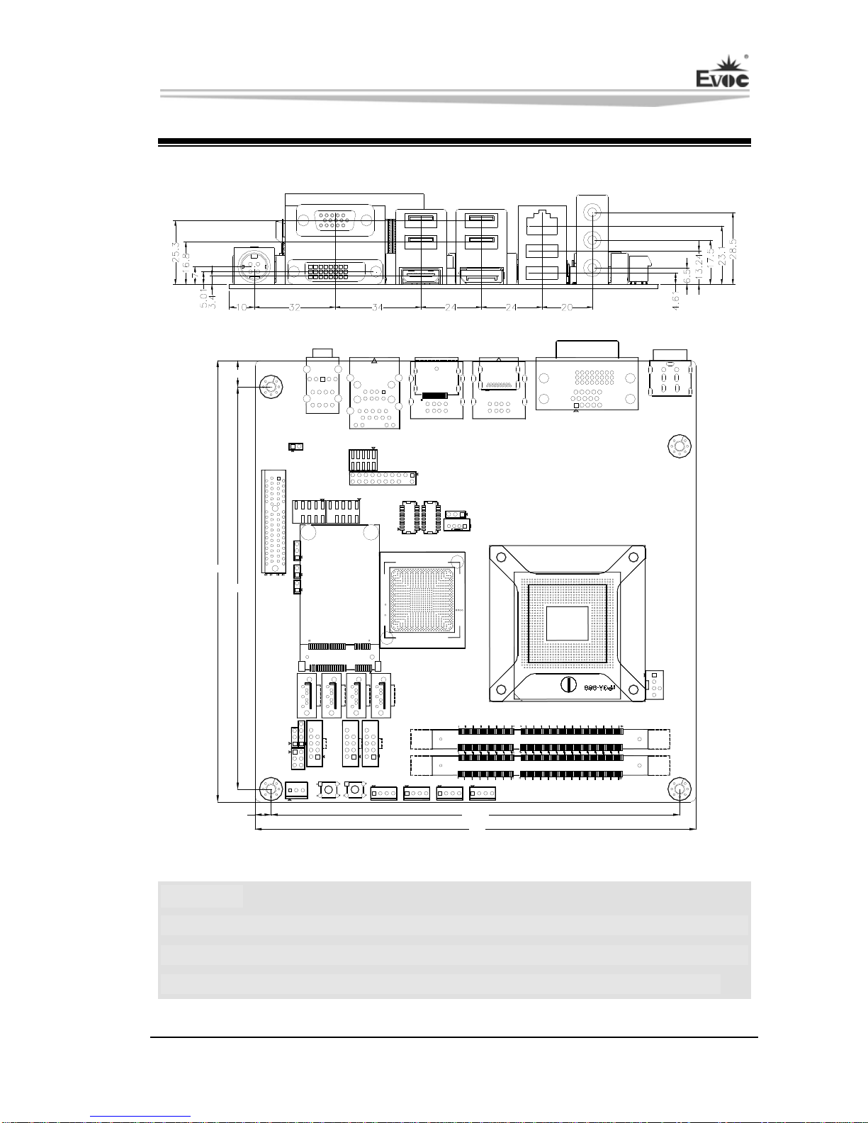
Product Outline
H1
H2
H3
H4
170
10.2
154.9
170
6.2 157.5
Unit: mm
Warning!
Please adopt appropriate screws and proper installation methods (including
board allocation, CPU and heat sink installation, etc); otherwise, the board may
be damaged. It is recommended to use M3x6 GB9074.4-88 screws at H1 ~ H4.
Chapter 2 Installation
- 6 - EC7-1817LNAR
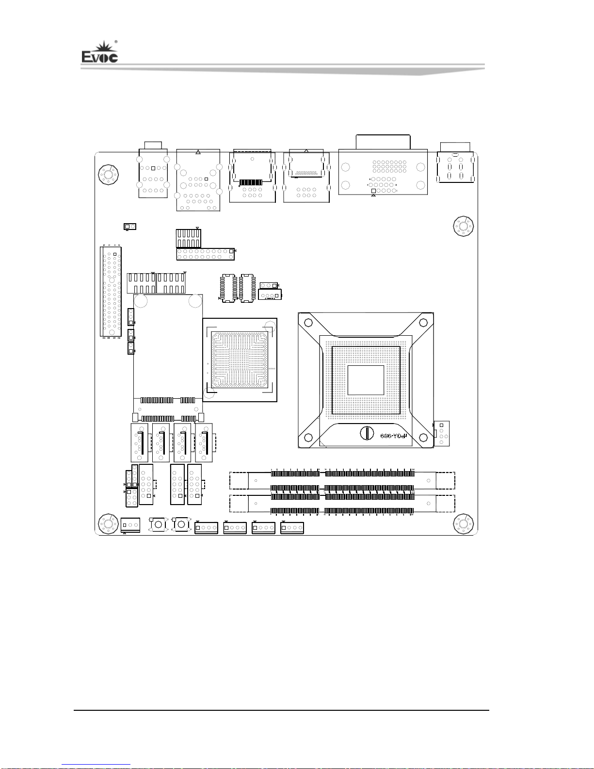
Locations of Connectors
15
H1
H2
H3
H4
J5
AUDIO1 J3
DP1
J2
HDMI1
J1
PWR1
JP2
PCIE1
COM1
COM2
GPIO1
J4
LVDS1
LVDS2
LCDB1
JLCD1
JP1
JM1
JCC1
U3
U1
CPUFAN1
DIMM1
DIMM2
J7 J8 J6
SW2 SW1
FP1
FP2
FP3 SATA1
SATA2
SATA3
SATA4
MPCIE1
2
52
51
SYSFAN1 PWR5 PWR4 PWR3 PWR2

Chapter 2 Installation
EC7-1817LNAR - 7 -
Structure
PCIE P1-4
PCIE X4 SLOT2
SATA3-4 3Gbps
IVY Bridge
LIN-IN
(Blue)
LIN-OUT
(Green)
MIC-IN
(PINK)
LPC
Hardware Monitor
RJ45+USB2.0*2
DP+USB2.0*2
HDMI+USB2.0*2
USB 2.0*6
USB2.0 Header
USB 2.0*3
SPI Flash
*2
SPI 8MB
SODIMM#A NO-ECC
1066/1333
SODIMM#B NO-ECC
1066/1333
Channel B DDR3
CONNECTOR
Channel A DDR3
PCIE P7
82579LM
RJ45
DISPLAY PORT
NCT6776F
VGA
DDPC
CRT
HDMI
DDPB
DMIX4
FDI
2CH LVDS
LVDS
24bit/18bit
WDT_OUT
DDPD
DVI-D
QM67
BGA989 25*25mm
TPM Header
80 Debug port
COM1(RS232)
COM2(RS232) 8bit GPIO
MINI PCIE CONN
PCIE P8
USB2.0
CougarPoint
Sandy Bridge
SATA
SATA1-2 6Gbps
HDA AUDIO
HDA
3.5" JACK
rPGA989(Socket G2)
37.5*37.5mm
Tip: How to identify the first pin of the jumpers and connectors
1. Observe the letter beside the socket; it would be marked with “1” or bold lines
or triangular symbols;
2. Observe the solder pad on the back; the square pad usually denotes the first pin.

Chapter 2 Installation
- 8 - EC7-1817LNAR
Jumper Setting
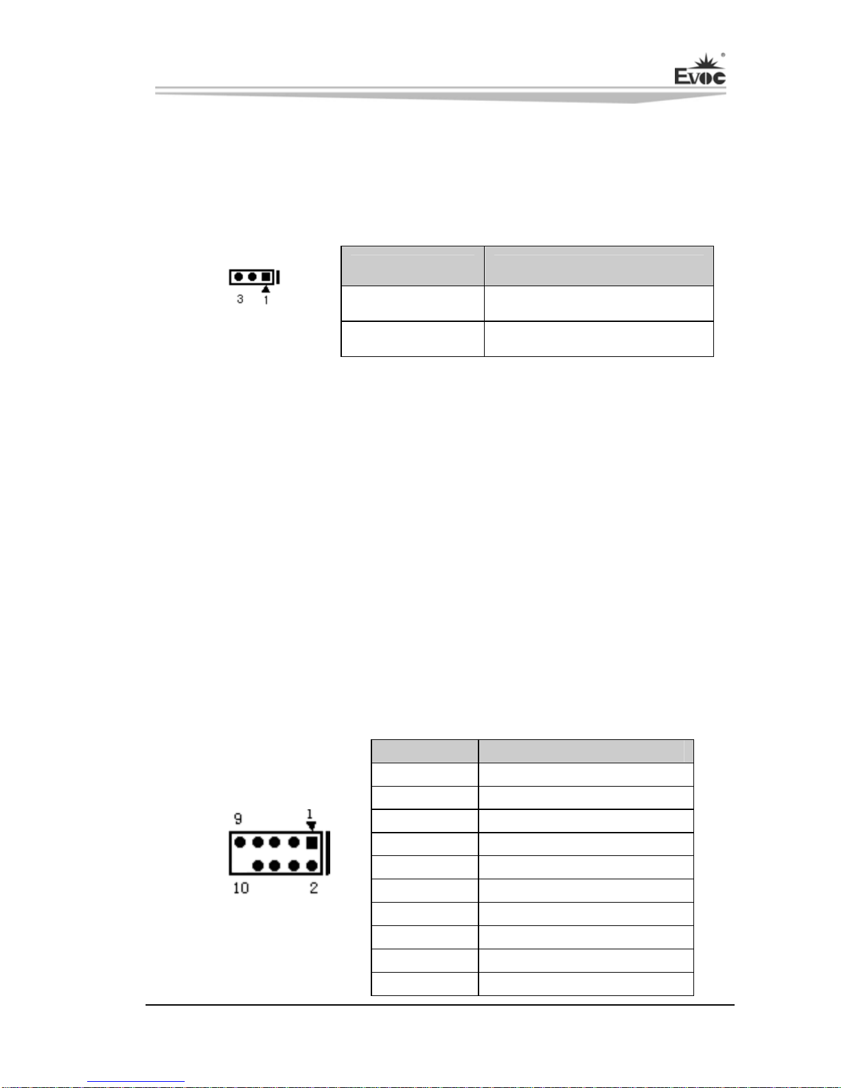
1. JCC1: Clear/Keep CMOS Setting (Pitch: 2.54mm)
CMOS is powered by the button battery on board. Clearing CMOS will restore
original settings (factory default). The steps are listed as follows: (1) Turn off the
computer and unplug the power cable; (2) Instantly short circuit JCC1; (3) Turn on
the computer; (4) Follow the prompt on screen to enter BIOS setup when booting the
computer, load optimized defaults; (5) Save and exit. Please set as follows:
Setup Function
1-2 Open Normal (Default)
JCC1 1-2 Short Clear the contents of CMOS and all BIOS settings
will restore to factory default values.
2. JM1: Clear/Keep ME Register Setting (Pitch: 2.54mm)
Setup Function
1-2 Open Normal (Default)
JM1 1-2 Short Clear the contents of ME RTC register and all the
settings will restore to factory default values.
3. JP1: Enable the Operating Voltage of LVDS and Embedded Panel (Pitch:
2.54mm)
Setup Function
1-2 Short Enabled LVDS Voltage (Default)
JP1 2-3 Short Enabled EDP Voltage
4. JP2: SPI Flash Safety Performance Setting (Pitch: 2.54mm)
Setup Function
1-2 Open Enable ME function and disable on-line refresh
BIOS. (Default)
JP2 1-2 Short Disable ME function while enable on-line refresh
BIOS.
Note: when short circuit JP2 (1-2), ME is disabled; an error prompt of “The system
doesn’t comply with the minimum requirement to install the software” will appear
when installing the AMT driver; therefore, before installing the ME driver, please set
the jumper cap of JP2 to “OFF” so as to enable ME.
Chapter 2 Installation
EC7-1817LNAR - 9 -
5. JLCD1: Select LCD Operating Voltage (Pitch: 2.54mm)
Different LCD screens have different voltages; the board provides two voltage
options, +3.3V and +5V. Only when the selected LCD voltage is in accord with the
LCD screen operating voltage in use, can the LCD screen operate normally. Please set
as follows:
Setup Function
1-2 Short +3.3V(Default)
JLCD1 2-3 Short +5V
Install the System Memory
The board provides two 204Pin DDRIII SO-DIMM slots (DIMM1/DIMM2). Please
pay attention to the following issues when installing the memory banks:
Open the buckles on both sides of the memory slot. When installing, align the
notch of the memory bank with that of the memory slot and gently insert the
module into the slot;
The memory of 1.5V DDRIII 1600MHz supported by Intel® Chipset can be used;
the maximum memory capacity supported by the board is up to 16GB;
It is recommended to use the memory bank with SPD to ensure stable operation.
Serial Port
The board provides two 2x5Pin serial ports (Pitch: 2.54mm), supporting RS-232
mode; the pin definitions are as follows:
Pin Signal Name
1 DCD#
2 RXD
3 TXD
4 DTR#
5 GND
6 DSR#
7 RTS#
8 CTS#
9 RI#
COM1/COM2
10 NA
Chapter 2 Installation
- 10 - EC7-1817LNAR
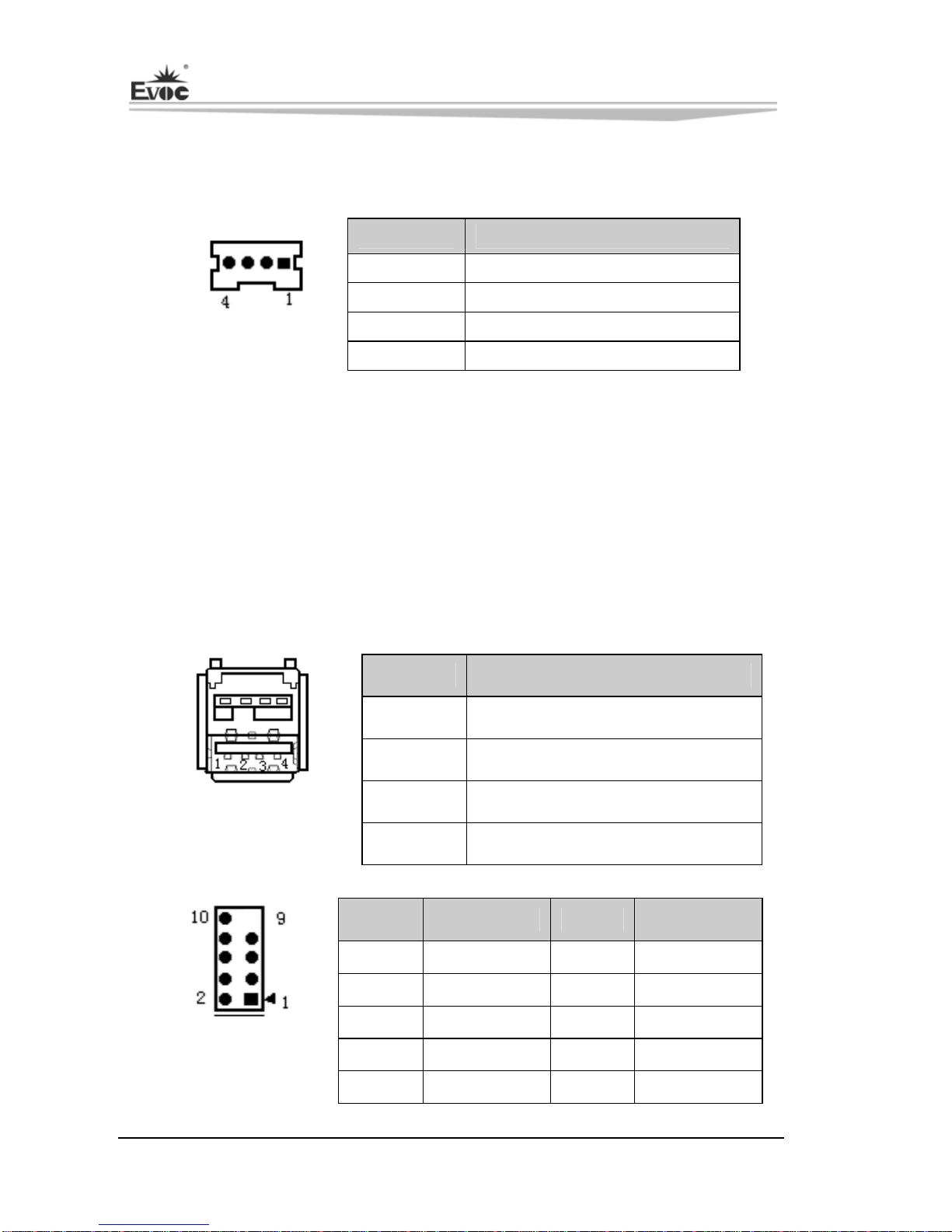
LCD Backlight Control Connector
The board provides one 1x4Pin LCD backlight control connector (Pitch: 2.0mm); the
pin definitions are as follows:
Pin Signal Name
1 +12V
2 LCD_BKLTCTL
3 LCD_BKLTEN
LCDB1 4 GND
VCC12 -------Backlight Power (The current is limited below 1A);
LCD_BKLTCTL---Backlight Control (The signal is output as PWM signal via North
Bridge directly; the voltage amplitude is between 0V-3.3V while the
duty cycle is between 0% ~ 100%);
LCD_BKLTEN ---Backlight Enable, Active High.
USB Port
The board provides twelve USB ports, six of which are standard ports while the other
six ports are brought out on three 2x5Pin headers (Pitch: 2.54mm).
Pin Signal Name
1 +5V
2 USB_Data-
3 USB_Data+
J5(USB1/USB2)
J2(USB3/USB4)
J3(USB9/USB10) 4 GND
Pin Signal Name Pin Signal Name
1 +5V 2 +5V
3 USB1_Data- 4 USB2_Data-
5 USB1_Data+ 6 USB2_Data+
7 GND 8 GND
J6(USB5/USB6)
J7(USB7/USB8)
J8(USB11/USB12) 9 NA 10 GND
Chapter 2 Installation
EC7-1817LNAR - 11 -
Display Connector
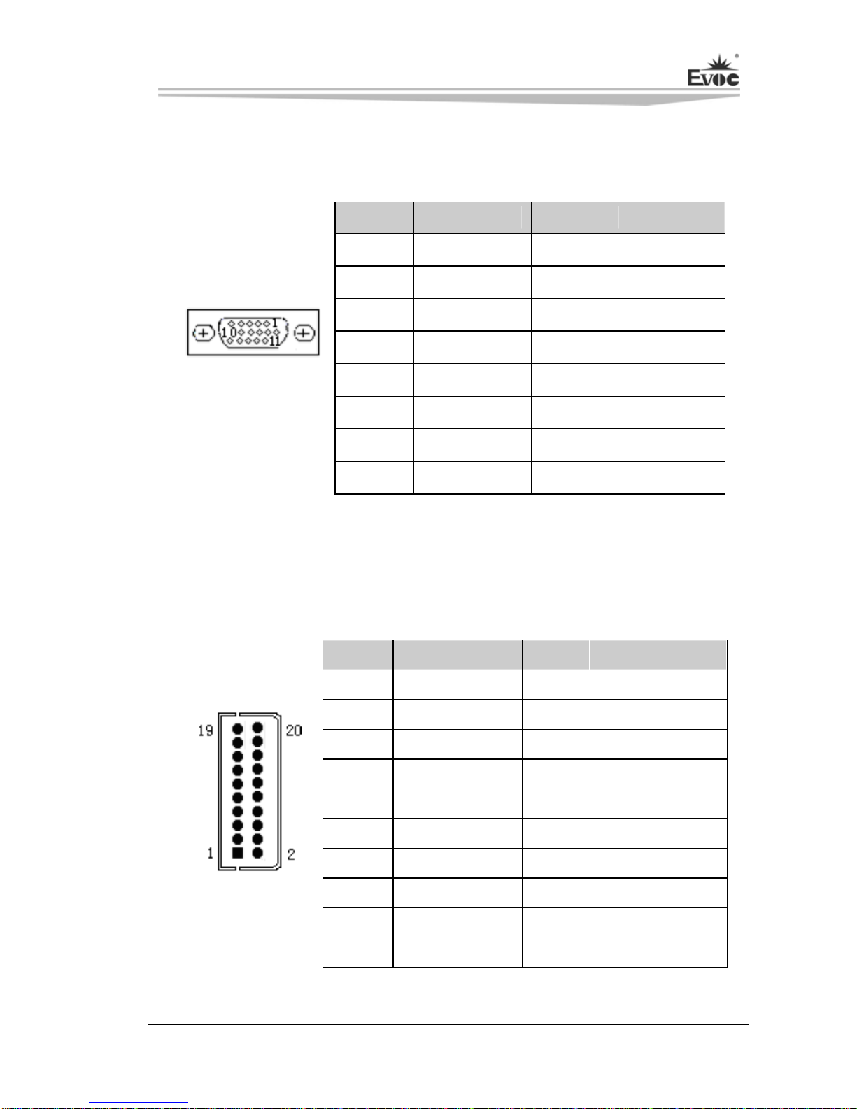
1、The board provides one standard DB15 VGA connector; the pin definitions are
as follows:
Pin Signal Name Pin Signal Name
1 Red 2 Green
3 Blue 4 NC
5 GND 6 GND
7 GND 8 GND
9 NC 10 GND
11 NC 12 DDCDATA
13 HSYNC 14 VSYNC
J1(VGA1)
15 DDCCLK
2、The board provides one dual-channel 24bitLVDS connector (LVDS1 and
LVDS2; Pitch: 1.0mm). When single channel 18-bit/24-bit LVDS screens are
adopted, the LVDS data cable shall be connected with LVDS1. The pin
definitions for dual-channel 24-bit LVDS are as follows:
Pin Signal Name Pin Signal Name
1 LVDSO_D0+ 2 LVDSO_D0-
3 GND 4 GND
5 LVDSO_D1+ 6 LVDSO_D1-
7 GND 8 GND
9 LVDSO_D2+ 10 LVDSO_D2-
11 GND 12 GND
13 LVDSO_CLK+ 14 LVDSO_CLK-
15 GND 16 GND
17 LVDSO_D3+ 18 LVDSO_D3-
LVDS1
19 VDD 20 VDD

Chapter 2 Installation
- 12 - EC7-1817LNAR
Pin Signal Name Pin Signal Name
1 LVDSE_D0+ 2 LVDSE_D0-
3 GND 4 GND
5 LVDSE_D1+ 6 LVDSE_D1-
7 GND 8 GND
9 LVDSE_D2+ 10 LVDSE_D2-
11 GND 12 GND
13 LVDSE_CLK+ 14 LVDSE_CLK-
15 GND 16 GND
17 LVDSE_D3+ 18 LVDSE_D3-
LVDS2
19 VDD 20 VDD
Note: LVDSOx indicates to dual scan the odd line of PANEL while LVDSEx
indicates to dual scan the even line of PANEL.
The LVDS socket adopted by the board is DF20G-20DP-1V while the
corresponding terminal type is DF20A-20DF-1C.
3、The board provides one Type A HDMI connector; the pin definitions are as
follows:
HDMI1
Pin Signal Name Pin Signal Name
1 TMDS Data2+ 2 TMDS Data2 Shield
3 TMDS Data2- 4 TMDS Data1+
5 TMDS Data1 Shield 6 TMDS Data1-
7 TMDS Data0+ 8 TMDS Data0 Shield
9 TMDS Data0- 10 TMDS Clock+
11 TMDS Clock Shield 12 TMDS Clock-
13 CEC 14 Reserved (NC on device)
15 SCL 16 SDA
17 DDC/CEC Ground 18 +5V
19 Hot Plug Detect

Chapter 2 Installation
EC7-1817LNAR - 13 -
4、Display Port
Pin Signal Name Pin Signal Name
1 LANE0P 2 GND
3 LANE0N 4 LANE1P
5 GND 6 LANE1N
7 LANE2P 8 GND
9 LANE2N
10 LANE3P
11 GND 12 LANE3N
13 GND 14 GND
15 AUXCHP 16 GND
17 AUXCHN 18 HPD
DP1
19 RETURN 20 DP_PWR
5、DVI-D Connector
Pin Signal Name Pin Signal Name
1 DATA2- 13 NC
2 DATA2+ 14 +5V
3 GND_DVI 15 GND
4 NC 16 HOTPLUG
5 NC 17 DATA0-
6 DDCCLK 18 DATA0+
7 DDCDATA 19 GND_DVI
8 NC 20 NC
9 DATA1- 21 NC
10 DATA1+ 22 GND_DVI
11 GND_DVI 23 CLK+
J1(DVI1)
12 NC 24 CLK-
Chapter 2 Installation
- 14 - EC7-1817LNAR
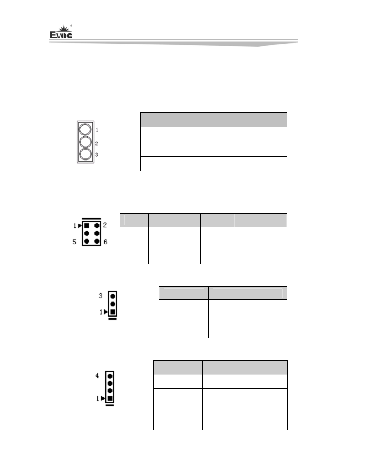
Audio Connector
AUDIO connector provides LINE-IN, LINE-OUT and MIC-IN connector. LINE-In
can be used to connect with audio signal input; LINE-OUT can be used to connect
with earphone or loudspeaker with more appropriate power; MIC-IN can be used to
connect with microphone to input sound.
Pin Signal Name
Blue LINE-IN
Green LINE-OUT
AUDIO1 Pink MIC-IN
Status Indicating and Control Connector
ATX Power Switch and HDD Indicating Connector (Pitch: 2.54mm)
Pin Signal Name Pin Signal Name
1 PWRBTN# 2 GND
3 GND 4 RESET#
FP1 5 HDD_LED- 6 HDD_LED+
Power Indicator Connector (Pitch: 2.54mm)
Pin Signal Name
1 PWR_LED+
2 NC
FP2 3 GND
Loudspeaker Output Connector (Pitch: 2.54mm)
Pin Signal Name
1 SPEAKER
2 NC
3 GND
FP3 4 +5V
Chapter 2 Installation
EC7-1817LNAR - 15 -
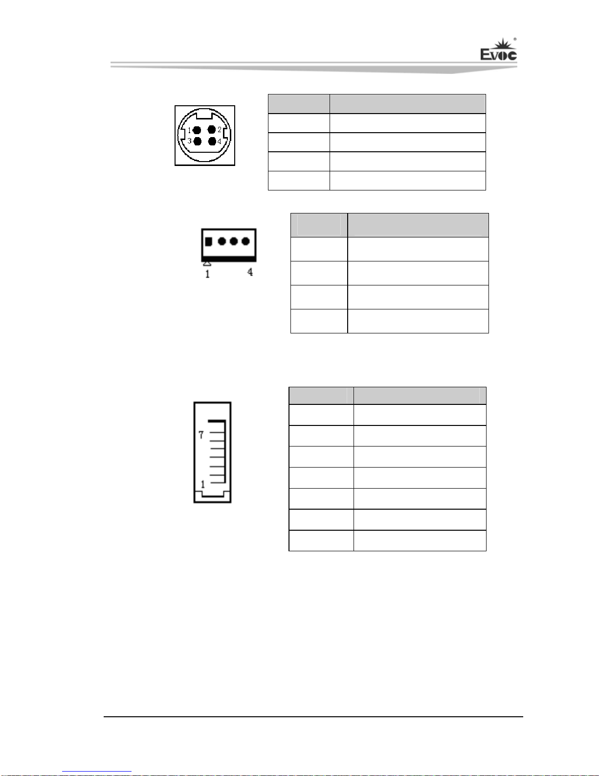
Power Connector
Pin Signal Name
1 +12V
2 +12V
3 GND
PWR1 4 GND
Pin Signal Name
1 +12V
2 GND
3 GND
PWR2~PWR5
Pitch: 2.54mm 4 +5V
SATA Connector
The board provides four SATA sockets and the pin definitions are as follows:
Pin Signal Name
1 GND
2 TX+
3 TX-
4 GND
5 RX-
6 RX+
SATA1/SATA2
SATA3/SATA4 7 GND
Hot-swap of SATAHard Disk
Notices for hot-swap of SATA hard disk:
1. The hard disk shall support SATA 2.0 and use 15-pin SATA hard disk power
connector.
2. The driver of chipset shall support the hot-swap of SATA hard disk.
3. Hot-swap of SATA hard disk with the operating system is forbidden when system
is powered-on.
Other manuals for EC7-1817LNAR
1
Table of contents
Other EVOC Motherboard manuals

EVOC
EVOC EC7-1817LNAR User manual

EVOC
EVOC EC3-1813 Series User manual

EVOC
EVOC EC0-1814 User manual

EVOC
EVOC CPC-3813CLD3N User manual

EVOC
EVOC CPC-1814CLD5NA-N User manual

EVOC
EVOC EC5-1817LNAR User manual

EVOC
EVOC EC0-1818-C236 User manual

EVOC
EVOC NET-1821VD2N User manual

EVOC
EVOC EPE-1814V2NAR User manual

EVOC
EVOC EC7-1818CLD2NA User manual


Popular Motherboard manuals by other brands

MSI
MSI H410M PRO user guide

PerfecTron
PerfecTron OXY5315A user manual

Texas Instruments
Texas Instruments THS3491RGT EVM user guide

Supermicro
Supermicro Supero PDSML-LN1+ user manual

Lattice Semiconductor
Lattice Semiconductor iCE40 Ultra user guide

Texas Instruments
Texas Instruments ADCx120Q1EVM-PDK user guide


