EVOC ec3-1813cld2na User manual

EC3-1813CLD2NA(B)
基于 Intel Luna Pier 平台 3.5 寸主板
3.5 ″Motherboard Based on Intel Luna Pier
Platform
Version:C00

Copyright Notice
Information offered in this manual is believed to be correct at the time of printing, and
is subject to change without prior notice in order to improve reliability, design and
function and does not represent a commitment on the part of the manufacturer. In no
event will the manufacturer be liable for direct, indirect, special, incidental, or
consequential damages arising out of improper installation and/or use, or inability to
use the product or documentation.
This user manual is protected by copyright. No part of this manual may be reproduced,
stored in any retrieval system, or transmitted, in any form or by any means,
mechanical, electronic, photocopied, recorded or otherwise, without the prior written
permission from the manufacturer.
Trademarks
EVOC is a registered trademark of EVOC Intelligent Technology Co., Ltd. Other
product names mentioned herein are used for identification purposes only and may be
trademark and/or registered trademarks of their respective companies.
Please visit our website: http://www.evoc.com for more information,
Hotline: 4008809666

Safety Instructions
1. Please read this manual carefully before using the product;
2. Leave the board or card in the antistatic bag until you are ready to use it;
3. Touch a grounded metal object (e.g. for 10 seconds) before removing the board
or card from the anti-static bag;
4. Before installing or removing a board, wear the ESD gloves or ESD wrist strap;
handle the board by its edges only;
5. Before inserting, removing or re-configuring motherboards or expansion cards,
first disconnect the computer and peripherals from their power sources to
prevent electric shock to human bodies or damage to the product;
6. Remember to disconnect the AC power cord from the socket before removing
the board or moving the PC;
7. For PC products, remember to disconnect the computer and peripherals from the
power sources before inserting or removing a board;
8. Before connecting or disconnecting any terminal, peripheral or any device, be
sure the system is powered off and all the power sources are disconnected;
9. After turning off the computer, wait at least 30 seconds before turning it back on.

Contents
Chapter 1 Product Introduction.....................................................................................1
Overview..................................................................................................................1
Mechanical Dimensions, Weight and Environment..................................................1
Typical Consumption ...............................................................................................2
Microprocessor.........................................................................................................2
Chipset .....................................................................................................................2
System Memory .......................................................................................................2
Display Function ......................................................................................................3
Network Function ....................................................................................................3
Audio Function ........................................................................................................3
Power Feature ..........................................................................................................3
Expansion Bus .........................................................................................................3
Watchdog Function ..................................................................................................4
Operating System.....................................................................................................4
On-board IO .............................................................................................................4
Chapter 2 Installation....................................................................................................5
Product Outline ........................................................................................................5
Locations of Connectors ..........................................................................................6
Structure...................................................................................................................7
Jumper Setting .........................................................................................................8
Display Connector....................................................................................................9
LVDS Backlight Control Connector ......................................................................10

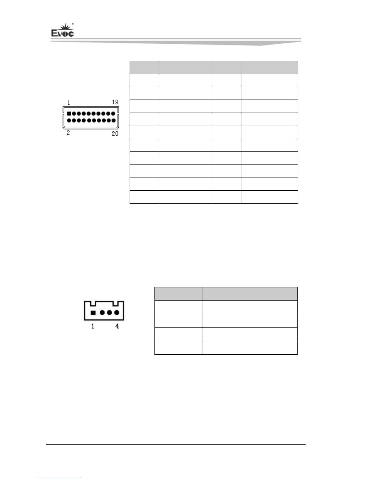
Audio Connector.................................................................................................... 11
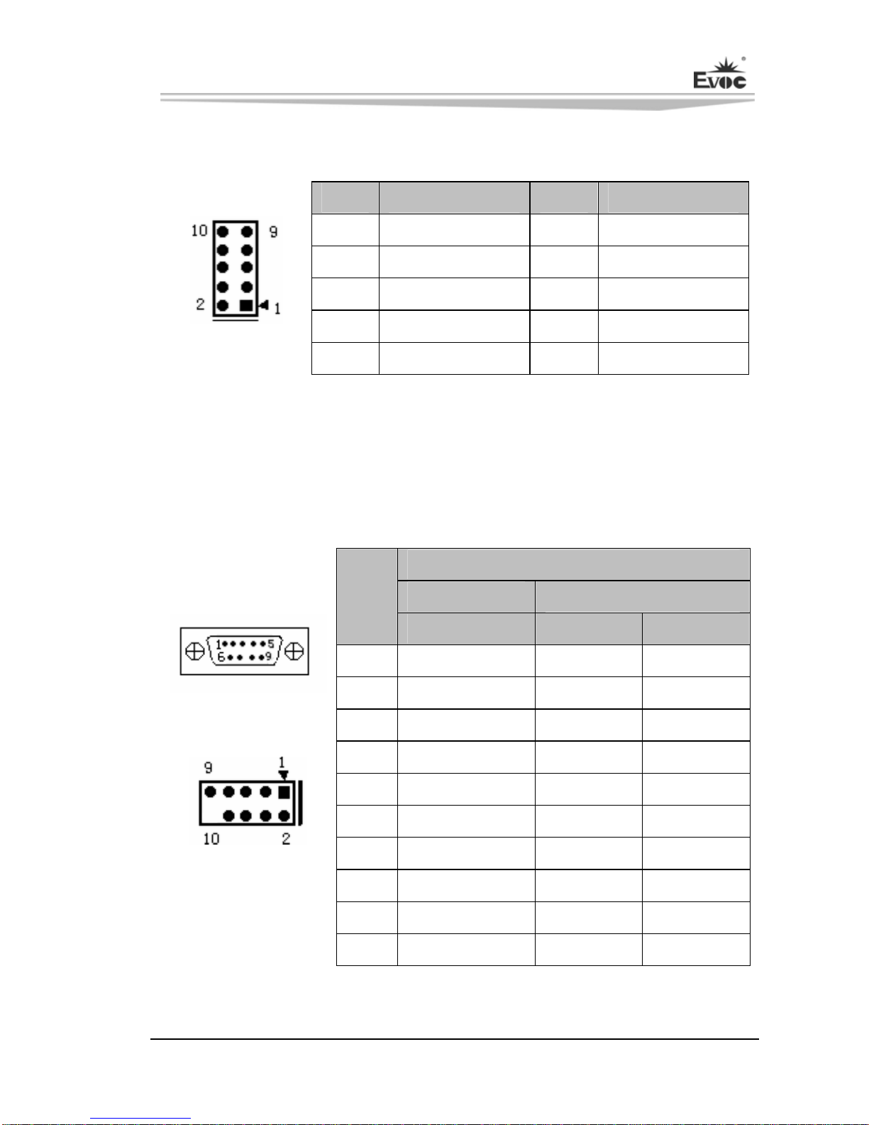
Serial Port ..............................................................................................................11
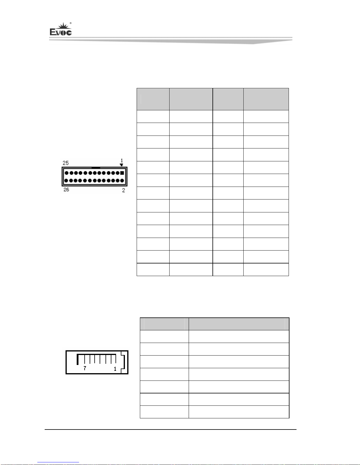
LPT Connector.......................................................................................................12
SATA Connector ....................................................................................................12
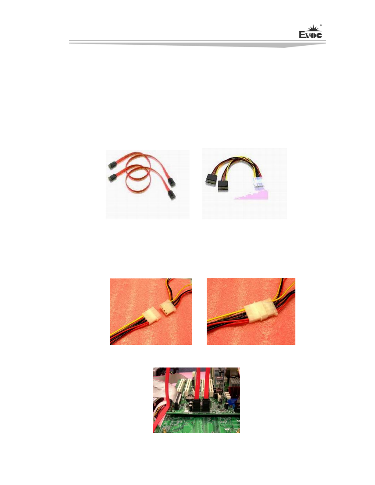
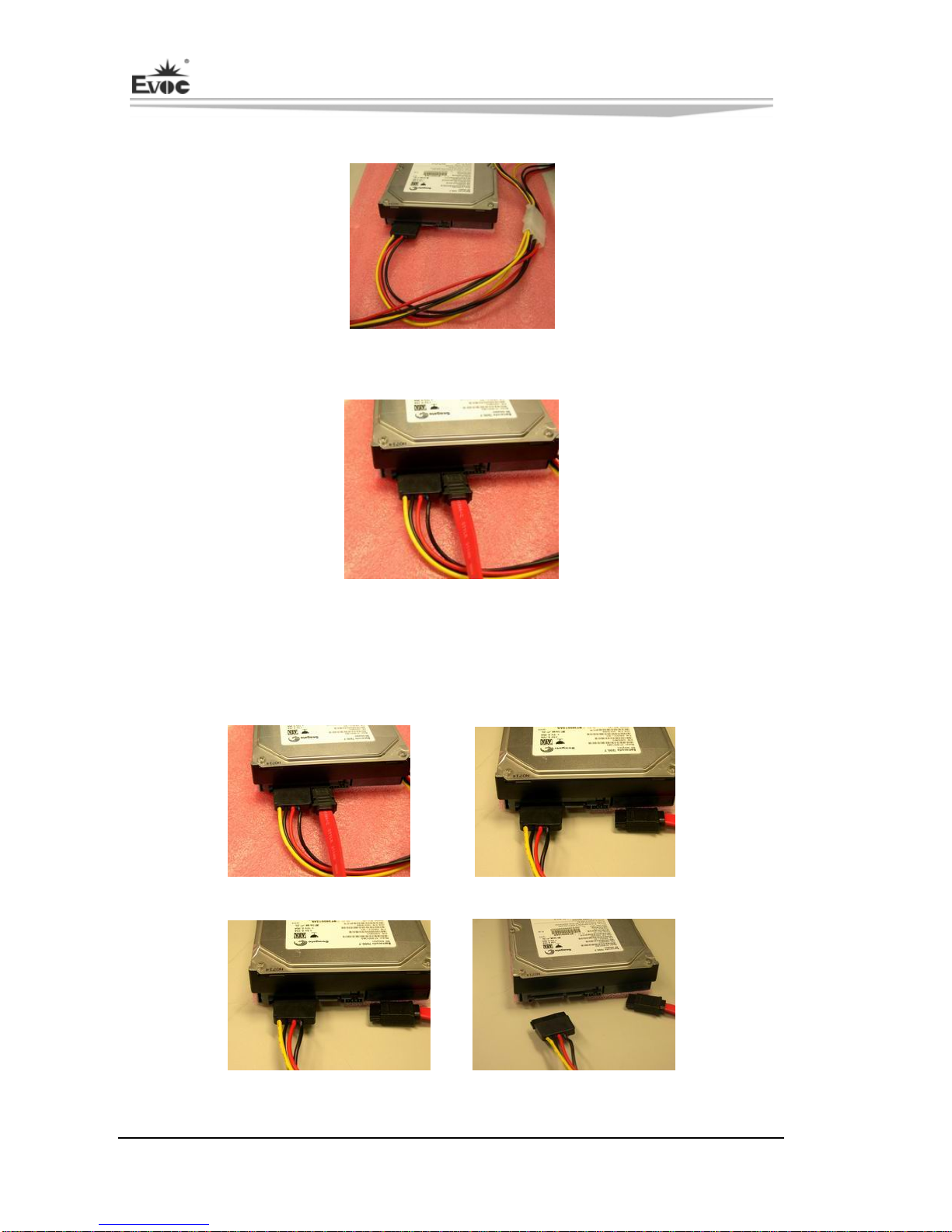
Hot-swap of SATA Hard Disk................................................................................13
LAN Port................................................................................................................15
USB Port ................................................................................................................16
2-in-1 Keyboard/Mouse Connector........................................................................16
GPIO Connector.....................................................................................................17
Status Control Connector on Front Panel...............................................................17
Power Connector....................................................................................................18
CPU Fan Connector ...............................................................................................18
CF Connector.........................................................................................................19
PCI-104 Bus Expansion Connector........................................................................20
Chapter 3 BIOS Setup ................................................................................................24
BIOS Overview......................................................................................................24
BIOS Parameter Setup ...........................................................................................24
Basic Function Setting for BIOS............................................................................25
System Resource Managed by BIOS under X86 Platform.....................................38
Chapter 4 Installing the Drivers.................................................................................. 42
Appendix ....................................................................................................................43
BPI Overview.........................................................................................................43
Troubleshooting and Solutions...............................................................................45

Chapter 1 Product Introduction
EC3-1813CLD2NA(B) - 1 -
Chapter 1 Product Introduction
Overview
EC3-1813 series are embedded motherboards with low power consumption, which are
developed based on Intel® Luna Pier Refresh platform and comply with 3.5″
single-board specification.
The board adopts Intel® Atom™ N455/D425/D525 processor + ICH8M technique
solution on-board. It provides one DDR3 SO-DIMM slot and 1GB/2GB DDR3
memory on-board (EC3-1813CLD2NA(B)-N455/D425 provides 1GB memory
on-board while EC3-1813CLD2NA(B)-D525 provides 2GB memory on-board); the
maximum memory capacity supported by N455/D425 is up to 2GB while that
supported by D525 is up to 4GB. It supports VGA, LVDS (18bit) display (Clone or
expanded mode); two 10/100/1000Mbps Ethernet controllers; PCI-104 bus expansion;
four USB2.0 ports; two SATA connectors; one Type I/II CF connector; one HD
Audio connector; four COMs (one supports RS-232/ RS-422/ RS-485); one PS/2
keyboard/mouse connector; one LPT connector; the board adopts 12V single power
supply.
Featuring Intel® low power consumption solution and small size design, the product
is ideally suitable for the applications in mechanical control, e-police, information
station, medical device and instrumentation, etc.
Mechanical Dimensions, Weight and Environment
Dimensions: 146.1mm (L) x 101.6mm (W) x 28mm (H);
Net Weight: 0.19kg ;
Operating Environment:

Chapter 1 Product Introduction
- 2 - EC3-1813CLD2NA(B)
Temperature: -20C ~ 60C;
-20C ~ 70C (with fan);
Humidity: 5% ~ 95% (non-condensing);
Storage Environment:
Temperature: -40C ~ 80C;
Humidity: 5% ~ 95% (non-condensing);
Typical Consumption
Configuration 1:
CPU: Intel Atom N455 1.66GHz 667 on-board;
Memory: Samsung DDR3 1G+ DDR3 1066 1GB ADATA on-board;
Configuration 2:
CPU: Intel Atom D525 1.80GHz 800 on-board;
Memory: Samsung DDR3 2G+ DDR3 1333 1GB Kingston on-board;
Microprocessor
Intel® Atom™ N455 (main frequency: 1.66GHz) or D425/D525 (main frequency:
1.8GHz) CPU on-board; internally integrates memory controller and graphics
controller.
Chipset
Intel® N455/D425/D525 +Intel® ICH8M.
System Memory
The maximum memory capacity supported by N455/D425 is up to 2GB. It provides
1GB DDR3 memory on-board and one 204Pin DDR3 memory slot, supporting

Chapter 1 Product Introduction
EC3-1813CLD2NA(B) - 3 -
667MHz Un-buffered NON-ECC DDR3 memory stick up to 1GB.
The maximum memory capacity supported by D525 is up to 4GB. It provides 2GB
DDR3 memory on-board and one 204Pin DDR3 memory slot, supporting
667/800MHz Un-buffered NON-ECC DDR3 memory stick up to 2GB.
Display Function
Integrated by Intel® N455/D425/D525 chip, assigning graphics memory according to
requirement and supporting VGA+LVDS dual display function.
EC3-1813CLD2NA(B)-N455: the maximum resolution supported by CRT is up to
1400x1050@60Hz; that supported by LVDS is 1280x800 or 1366x768.
EC3-1813CLD2NA(B)-D525/D425: the maximum resolution supported by CRT is up
to 2048x1536@60Hz; that supported by LVDS is 11366x768.
Network Function
Provides two 10/100/1000Mbps LAN ports; LAN1 adopts standard RJ45 connector,
supporting Wake-on-LAN function; LAN2 is brought out in 2x7Pin header.
Audio Function
Adopts standard HDA chip, supporting MIC-IN, LINE-IN and LINE-OUT function.
Power Feature
Adopts standard 2x2pin 12V ATX power connector, supporting single 12V power
supply.
Expansion Bus
One PCI-104 slot, expandable to 4 x PCI Master.

Chapter 1 Product Introduction
- 4 - EC3-1813CLD2NA(B)
Watchdog Function
255 levels, programmable by minute or second;
Supports watchdog timeout interrupt or reset system.
Operating System
Supported OSs: WIN2000, WINXP, WIN7, Linux and WINCE;
On-board IO
Four serial ports: COM1 is brought out in DB9 connector, supporting Modem
wake-up function; the remaining three are brought out in 2x5Pin headers;
COM2 supports RS-232/RS-422/RS-485 mode while the remaining three ports
only support RS-232 mode;
One LPT connector, brought out in 2x13Pin header;
One CF card connector;
Two SATA connectors;
One HD Audio connector, brought out in 2x5Pin header;
Four USB2.0 ports, two of which are brought out in connectors directly while
the other two ports are brought out in 2x5Pin headers;
One PS/2 connector, brought out in 2-in-1 connector;
One 8-bit digital IO connector, brought out in 2x5Pin header.
Tips: how to identify the alarms
1. Long “beep” indicates system memory error;
2. Short “beep” indicates to power on the computer.

Chapter 2 Installation
EC3-1813CLD2NA(B) - 5 -
Chapter 2 Installation
Product Outline
H1
H2
H4
H3
Unit: mm
Warning!
Please adopt appropriate screws and proper installation methods (including
board allocation, CPU and heat sink installation, etc); otherwise, the board may
be damaged. It is recommended to use M3x6 GB9074.4-88 screws at H1 ~ H4.

Chapter 2 Installation
- 6 - EC3-1813CLD2NA(B)
Locations of Connectors
H1
JP1 JP2 JP4
JP3 JP5
COM2
KM1
COM1
JCC1
COM3
GPIO1 J3
COM4
LPT1
VGA1
LAN1
J2
LAN2
AUDIO1
H2
H4
H3
J1
CF1
JP6
JCF1
PWR2
SATA2
SATA1
DIMM1
JLCD1
PWR1
LVDS1
CPUFAN1
FP2
FP3
FP1
LCDB1

Chapter 2 Installation
EC3-1813CLD2NA(B) - 7 -
Structure
ICH8M
BIOS
Super
I/O
PCI-104PCI BUS
PCIeX1
2.0 UHCI/EHCI
KB/MOUSE
LPT COM1&COM3&COM4 RS232
SODIMM
AUDIO
Hardware
Monitor
LVDS
CONN
USB X 4 ports
X8 1GB/2GB
VGA
DB15
DDR3
SATA
SPI
HDA Audio
COM2 RS232/RS422/RS485
DMI X4
PCIeX1
10/100/1000Mbps
Lan
Pineview
M/D
LAN2
8
路
GPIO
ON Board
SATA X 2 PORTS
HDA
LAN1
TDP 2.4W
SMBUS
LPC
TypeI/II
CF
IDE BUS
18 Bit single channel
10/100/1000Mbps
Lan
TDP D525:13W
N455:5.5W
DDR3
Tip: How to identify the first pin of the jumpers and connectors
1. Observe the letter beside the socket: the first pin is usually marked with “1” or
bold lines or triangular symbols;
2. Observe the solder pad on the back; the square pad is the first pin.

Chapter 2 Installation
- 8 - EC3-1813CLD2NA(B)
Jumper Setting
1. Clear/Keep CMOS Setting (Pitch: 2.0 mm)
CMOS is powered by the button battery on board. Clearing CMOS will restore
original settings (factory default). The steps are listed as follows: (1) Turn off the
computer and unplug the power cable; (2) Instantly short circuit JCC1; (3) Turn on
the computer; (4) Follow the prompt on screen to enter BIOS setup when booting the
computer, load optimized defaults; (5) Save and exit. Please set as follows:
Setup Function
1-2 Open Normal ((Default)
JCC1 1-2 Short Clear the contents of CMOS and all BIOS
settings will restore to factory default values.
2. Select LCD Operating Voltage (Pitch: 2.0mm)
The board provides two voltage options, 3.3V and 5V. Only when the selected LCD
voltage is in accord with the LCD screen operating voltage in use, can the LCD screen
operate normally. Please set as follows:
Setup Function
1-2 Short +3.3V(Default)
JLCD1 2-3 Short +5V
3. Select CF Card Operating Voltage (Pitch: 2.0mm)
The board provides two voltage options, 3.3V and 5V. Only when the selected CF
card voltage is in accord with the CF card operating voltage in use, can the system
operate stably. Please set as follows:
Setup Function
1-2 Short +3.3V
JCF1 2-3 Short +5V(Default)
Note: this option is set to comply with different CF cards; as for the CF card
without specified operating voltage, please choose the CF card voltage according
to actual usage.

Chapter 2 Installation
EC3-1813CLD2NA(B) - 9 -
4. Choose Mode for COM2 (Pitch: 2.0mm)
Mode Selection
Pin
Setting RS-232
(Default) RS-422 RS-485
JP1 1-2 5-6 3-4
JP2 1-2 2-3 2-3
JP3 1-2 2-3 2-3
JP4 1-2 2-3 2-3
JP1
JP2 ~ JP5 JP5 1-2 2-3 2-3
5. Choose the VIO Voltage of PCI-104 (Pitch: 2.0mm)
Setup Function
1-2 Short +3.3V
JP6 2-3 Short +5V
Note: The VIO of PCI-104 supplies power for the bus signal of the expansion
device; the default setting is unset. Please choose the VIO voltage according to
the expansion device to be connected. The operating voltage of the expanded PCI
devices shall be the same.
Display Connector
1) VGA Connector
Pin Signal Name Pin Signal Name
1 Red 2 Green
3 Blue 4 NC
5 GND 6 GND
7 GND 8 GND
9 NC 10 GND
11 NC 12 DDCDATA
13 HSYNC 14 VSYNC
VGA1
15 DDCCLK

Chapter 2 Installation
- 10 - EC3-1813CLD2NA(B)
2) Single-channel 18-bit LVDS Connector
Pin Signal Name Pin Signal Name
1 LVDS_D0+ 2 LVDS_D0-
3 GND 4 GND
5 LVDS_D1+ 6 LVDS_D1-
7 GND 8 GND
9 LVDS_D2+ 10 LVDS_D2-
11 GND 12 GND
13 CLK+ 14 CLK-
15 GND 16 GND
17 NC 18 NC
LVDS1
(Pitch: 1.0mm)
19 VDD 20 VDD
Note: the LVDS socket model adopted by the board is DF20G-20DP-1V; the
corresponding terminal model is DF20A-20DF-1C.
LVDS Backlight Control Connector
The board provides one 1x4Pin LCD backlight control connector (Pitch: 2.0mm); the
pin definitions are as follows:
Pin Signal Name
1 VCC_LCDBKLT
2 LCD_BKLTCTL
3 LCD_BKLTEN
LCDB1(Pitch: 2.0mm)
4 GND
Note:
VCC_LCDBKLT---Backlight Power (The current is limited below 1A);
LCD_BKLTCTL---Backlight Control (The signal is output as PWM signal via North
Bridge directly; the voltage amplitude is between 0V-3.3V while the duty cycle is
between 0% ~ 100%);
LCD_BKLTEN ---Backlight Enable, Active High. (The signal is output as CMOS
output via North Bridge directly; the voltage amplitude is between 0V-3.3V).

Chapter 2 Installation
EC3-1813CLD2NA(B) - 11 -
Audio Connector
The board provides one 2x5Pin AUDIO pin header (Pitch: 2.0mm).
Pin Signal Name Pin Signal Name
1 LOUT_R 2 LOUT_L
3 GND_AUDIO 4 GND_AUDIO
5 LIN_R 6 LIN_L
7 GND_AUDIO 8 GND_AUDIO
AUDIO1 9 MIC_L 10 MIC_R
Serial Port
The board provides one super-slim DB9 serial port socket and three 2x5Pin serial port
pin headers (Pitch: 2.0mm). COM2 supports RS-232/RS-422/RS-485 mode while the
other three serial ports support RS-232 mode.
Signal Name
COM1 ~ COM4 COM2
Pin
RS-232 RS-422 RS-485
1 DCD# TXD- Data-
2 RXD TXD+ Data+
3 TXD RXD+ NC
4 DTR# RXD- NC
5 GND GND GND
6 DSR# NC NC
7 RTS# NC NC
8 CTS# NC NC
9 RI# NC NC
COM1
COM2 ~ COM4
10 NA NA NA
Note: the data transmission direction is controlled automatically at RS-485 mode.

Chapter 2 Installation
- 12 - EC3-1813CLD2NA(B)
LPT Connector
The board provides one 2x13Pin LPT connector (Pitch: 2.00mm); the pin definitions
are as follows:
Pin Signal
Name Pin Signal
Name
1 STB# 2 AFD#
3 PD0 4 ERR#
5 PD1 6 INIT#
7 PD2 8 SLIN#
9 PD3 10 GND
11 PD4 12 GND
13 PD5 14 GND
15 PD6 16 GND
17 PD7 18 GND
19 ACK# 20 GND
21 BUSY 22 GND
23 PE 24 GND
LPT1
25 SLCT 26 NC
SATA Connector
The board provides two standard vertical SATA sockets.
Pin Signal Name
1 GND
2 TX+
3 TX-
4 GND
5 RX-
6 RX+
SATA1/SATA2
7 GND

Chapter 2 Installation
EC3-1813CLD2NA(B) - 13 -
Hot-swap of SATA Hard Disk
Notes for hot-swap of SATA hard disk:
1. The hard disk shall support SATA 2.0 and use 15-pin SATA hard disk power
connector.
2. The driver of chipset shall support the hot-swap of SATA hard disk.
3. Hot-swap of SATA hard disk with the operating system is forbidden when system
is powered-on.
Please carry out hot plugging as follows. Improper operation may destroy the hard
disk or result in data loss.
Hot Plug
Step 1: Please plug the 1 x 4 pin SATA power connector (white) into the power adapter.
SATA Data Cable SATA Power Cable

Chapter 2 Installation
- 14 - EC3-1813CLD2NA(B)
Step 2: Please connect the SATA data cable to the SATA connector on board.
Step 3: Please connect the 15-pin SATA power connector (black) to the SATA hard
disk.
Step 4: Please connect the SATA data cable to the SATA hard disk.
Hot Unplug
Step 1: Uninstall the hard disk from the device manager.
Step 2: Unplug the data cable from the SATA hard disk.
Step 3: Unplug the SATA 15-pin power connector (black) from the SATA hard disk.

Chapter 2 Installation
EC3-1813CLD2NA(B) - 15 -
LAN Port
1. The board provides one standard 10/100/1000Mbps RJ45 port.
LAN1
LILED
(Dual-Color: O/G)
LAN Speed
Indicator
ACTLED
(Green)
LAN Activity
Status Indicator Green 1000Mbps
Blink Data being
transmitted Orange 100Mbps
Off No data being
transmitted Off 10Mbps
2. The board provides one 2x7Pin 10/100/1000Mbps LAN port, which shall be fixed
with the chassis by conversion cable before connecting with peripherals. The pin
definitions are as follows:
Pin Signal Name Pin Signal Name
1 MX0+ 2 MX0-
3 MX1+ 4 MX1-
5 MX2+ 6 MX2-
7 MX3+ 8 MX3-
9 GND 10 GND
11 LINK_LED+
(SPEED1000-) 12 LINK_LED-
(SPEED100-)
LAN2
(Pitch: 2.0mm)
13 ACT_LED+ 14 ACT_LED-
Other manuals for ec3-1813cld2na
1
This manual suits for next models
1
Table of contents
Other EVOC Motherboard manuals

EVOC
EVOC CPC-1814CLD5NA-N User manual

EVOC
EVOC EC0-1814 User manual

EVOC
EVOC EC0-1815V2NAR User manual

EVOC
EVOC EC5-1817LNAR User manual

EVOC
EVOC CPC-3813CLD3N User manual

EVOC
EVOC EC7-1813CLD2NA SERIES User manual

EVOC
EVOC EC7-1818CLD2NA User manual

EVOC
EVOC EC7-1817LNAR User manual

EVOC
EVOC 104-1649CLD2NA Series User manual

EVOC
EVOC EC3-1813 Series User manual