ENS7003R0 KO06 2010
INSTALLATIONAND WIRING
CAUTION
INSTALLATION
When Installing thisProduct
1.Read theseinstructionscarefully. Failuretofollow
themcoulddamagetheproduct orcausea
hazardouscondition.
2.Check theratingsgivenintheinstructionsand
markedon theproduct tomakesuretheproduct is
suitablefortheapplication.
3.Installermust beatrained, experienced, flame
safeguardservicetechnician.
4.Afterinstallation iscomplete, check out theproduct
operation asprovidedintheseinstructions.
WARNING
Fire orExplosion Hazard.
Can cause propertydamage,
severe injury, ordeath.
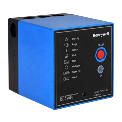
Carefullyfollowsafetyrequirementswheninstalling a
burnercontrol.
CAUTION
Electrical Shock Hazard orEquipment/
Control Damage.
Can cause electrical shock orequipment
damage.
Disconnect powersupplybeforebeginning
installation.
IMPORTANT
1.Wiring connectionsfortherelaymodulesareunique;
refertoFig. 3-2ortheappropriateSpecificationsfor
individualsubbasewiring.
2.Wiring must complywithall applicablecodes,
ordinancesand regulations.
3.Wiring must complywithNECClass 1
(LineVoltage)wiring.
4.LoadsconnectedtotheDBC2000Emust not exceed
thoselistedon therelaymodulelabelorthe
Specifications; see Table3.
5.Limitsand interlocks must beratedtosimultaneously
carryand breakcurrent totheignition transformerand
fuelvalve(s).
6.All externaltimersmust belistedor
componentrecognizedbyauthoritieswho haveproper
jurisdiction.
7.Foron-off gas-firedsystems, someauthoritieswho
havejurisdiction prohibit thewiring of anylimit or
operating contactsinseriesbetweentheflame
safeguardcontroland themainfuelvalve(s).
8.TwoUVflamedetectorscan beconnectedinparallel.
9.Thisequipment generates, usesand can radiate
radiofrequency energyand, if not installedand used
inaccordancewiththeinstructions, can cause
interferencewithradiocommunications. It hasbeen
testedand found tocomplywiththelimitsforaClass
Bcomputing deviceof Part 15 of FCC rules, which
aredesignedtoprovidereasonableprotection
against suchinterferencewhenoperatedinan
industrialorcommercialenvironment. Operation of
thisequipment inaresidentialareacan cause
interference, inwhichcase, theusers, at theirown
expense, mayberequiredtotakewhatevermeasures
arerequiredtocorrect thisinterference.
10.Thisdigitalapparatuscomplieswiththerequirements
asstatedintheEN298:2003.
11.Donot install theBurnerControllerunderany
circumstancesinthefollowing locations.
Wherechemicalsorcorrosivegasesarepresent,
suchasammonia, sulfur, chlorine, ethylene
compounds, acids, etc.
②Install therelaymodulewheretherelative
humidityneverreachesthesaturation point. The
relaymoduleisdesignedtooperateina
maximum85%relativehumiditycontinuous,
noncondensing, moistureenvironment.
Condensing moisturecan causeasafety
shutdownordamagethedevice.
③Wheretemperaturesexceedthemaximum
specification forthisdevice.
④Wherevibration exceeds0,5G continuous
vibration.
12.Donot bundlepowerwiring and high voltageignition
cablewiththeflamedetectorwiring, orrun themin
parallelwithinthesameconduit. High voltagecables
must bekept separatedat least 10 cmfromthe
BurnerController.
13.Usepropergrounding workinaccordancewiththe
engineering standardsforelectricalequipment
14.Connect thehigh voltagecableof theignition
transformerproperlytotheignition electrode. Apoor
connection can causean electricalshock ordamage
theequipment. Additionallytheignition transformer
must beproperlygroundedaccording thestandards.
