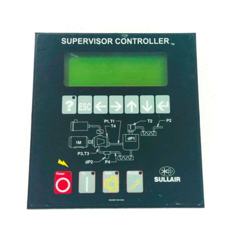
Sullair SUPERVISOR I User manual

SUPERVISOR
Part Number 02250051---610
eSullair Corporation, 1994
Effective 1/94
INSTRUCTION MANUAL
I

AIR CARE
SEMINAR TRAINING
Sullair Air Care Seminars are 3---day courses that provide hands---on instruction
in the proper operation, maintenance and service of Sullair equipment.
Individual seminars on Industrial compressors and compressor electrical
systems are presented at regular intervals throughout the year at a dedicated
training facility at Sullair’s corporate headquarters in Michigan City, Indiana.
Instruction includes discussion of the function and installation of Sullair service
parts, troubleshooting of the most common problems, and actual equipment
operation. The seminars are recommended for maintenance and service
personnel.
For detailed course outlines, schedule and cost information contact:
Sullair Corporate Training Department
1---800---SULLAIR or 219---879---5451 (ext. 1816)
--- O r W r i t e ---
Sullair Corporation
3700 E. Michigan Blvd.
Michigan City, IN 46360
Attn: Service Training Department

TABLE OF CONTENTS
Section 1 PAGE
SAFETY 11.1 GENERAL
11.2 ELECTRIC SHOCK
11.3 DECALS
Section 2
DESCRIPTION 32.1 INTRODUCTION
32.2 INSTRUMENTATION, FUNCTIONAL
DESCRIPTION
42.3 GENERAL
42.4 PURPOSE OF CONTROLS
52.5 AUTOMATIC OPERATION
52.6 SUPERVISOR IOUTPUT RELAYS
52.7 SUPERVISOR ISPECIAL FUNCTION INPUTS
62.8 SUPERVISOR IAUXILIARY DIGITAL INPUTS
62.9 OPTIONAL FACTORY CONFIGURATIONS
Section 3
PROGRAMMING PROCEDURES
73.1 SUPERVISOR IMICROCONTROLLER
PROGRAMMING
Section 4
START-- UP PROCEDURES
84.1 MOTOR ROTATION DIRECTION CHECK
84.2 INITIAL START --- UP PROCEDURE
84.3 SUBSEQUENT START --- UP PROCEDURE
84.4 SHUTDOWN PROCEDURE
Section 5
MAINTENANCE AND
TROUBLESHOOTING 95.1 CONTROL SYSTEM ADJUSTMENT
95.2 TROUBLESHOOTING GUIDE
12 5.3 MESSAGE DISPLAY DEFINITIONS
12 5.4 TROUBLE INDICATION SETPOINTS


Section 1
SAFETY
1
1.1 GENERAL
Sullair Corporation and its subsidiaries designs and
manufactures all of our products so they can be op-
erated safely. However, the responsibility for safe
operation rests with those who use and maintain
these products. For safe machine operation it is vi-
tally important to review all safety precautions noted
in the Safety Section of your compressor’s Opera-
tor’s Manual. The precautions listed there, as well
as those following, are offered as a guide which, if
conscientiously followed, will minimize the possibil-
ity of accidents throughout the useful life of this
equipment.
The compressor should be operated only by those
who have been trained and delegated to do so, and
who have read and understood their compressor’s
Operator’s Manual. Failure to follow the instruc-
tions, procedures and safety precautions listed
here and in the Operator’s Manual may result in ac-
cidents and injuries.
NEVER start the compressor unless it is safe to do
so. DO NOT attempt to operate the compressor with
a known unsafe condition. Tag the compressor and
render it inoperative by disconnecting and locking
out all power at source or otherwise disabling its
prime mover so others who may not know of the un-
safe condition cannot attempt to operate it until the
condition is corrected.
Use and operate the air compressor only in full com-
pliance with all pertinent OSHA requirements and all
pertinent Federal, State, and Local codes or re-
quirements. Read the CIMA Safety Manual (P/N
250023-146) prior to operation or performing main-
tenance on this equipment.
DO NOT modify the compressor and/or controls in
any way except with written factory approval.
1.2 ELECTRICAL SHOCK
A. Keep all parts of the body and any hand-held
tools or other conductive objects away from ex-
posed live parts of electrical system. Maintain dry
footing, stand on insulating surfaces and DO NOT
contact any other portion of the compressor when
making adjustments or repairs to exposed live parts
of the electrical system.
B. Attempt repairs only in clean, dry and well lighted
and ventilated areas.
C. Stay clear of the compressor during electrical
storms! It can attract lightning.
1.3 DECALS
See Figure 1-1. The Supervisor I control panel con-
tains several decals which contain necessary in-
formation for safe performance. These decals
should never be removed. If a decal becomes dam-
aged, contact your nearest Sullair Distributor or the
Sullair Corporation factory Service Department for
replacement parts (Note: When ordering new de-
cals, use part number printed on decal face.).

Section 1
SAFETY
2
Figure 1-1 Decals
* OSHA and FDA guidelines are superceded by any Federal, State or Local regulations whenever applicable.
*
*

Section 2
DESCRIPTION
3
2.1 INTRODUCTION
Your compressor is equipped with a Supervisor I mi-
croprocessor controller, replacing the standard
electro-mechanical control of pushbuttons,
switches and gauges. This manual explains the
functions and operation of the Supervisor control as
well as how to program its features for your particuZ-
lar application.
2.2 INSTRUMENTATION, FUNCTIONAL DE-
SCRIPTION
Refer to Figure 2-1. The Supervisor Icontrol panel
consists of displays for pressure, temperature, time
(run hours), and a status message. Default pres-
sure is line pressure (P2) which is normally dis-
played with pad selections for sump pressure, fluid
pressure, separator differential and fluid filter differ-
ential. Default temperature is unit discharge temper-
ature (T1) which is normally displayed with a pad
selection for injection fluid temperature. An LED
map provides a graphic illustration of the points be-
ing monitored. Operator controls consist of EMER-
GENCY STOP, ON/OFF, monitor display pads and
programming pads. All compressor control, pres-
sure and temperature displays are provided in the
Supervisor I.
SThe line (terminal) pressure transducer (P2) is
connected to the dry side of the receiver down-
stream from the check valve and continually moni-
tors the plant air pressure.
SThe sump pressure transducer (P1) monitors
the sump/unit discharge pressure.
SInjection oil pressure (P3) monitors oil pressure
at the point of injection into the compressor down-
stream of the oil filter.
SFilter oil pressure (P4) monitors oil pressure
ahead of the oil filter and is used with P3 to calculate
oil filter differential; Y P2=P4-P3.
SThe discharge temperature probe (T1) monitors
the temperature of the air leaving the compressor
unit. For both air-cooled and water-cooled compres-
sors the normal reading is approximately 180ºF
(82ºC) based on 80ºF (27ºC) ambient temperature.
SThe injection temperature probe (T2) monitors
the temperature of the fluid just before it is injected
into the unit.
SThe air filter maintenance switch monitors the
condition of the air intake filter. When the Supervi-
sor displays the message “AIR FILTER MAINT
RQD”, filter service is required.
STheON/OFF pad turns the compressor on and
off.
SThe hour display records cumulative hours of op-
Figure 2-1 Supervisor Control Panel

Section 2
DESCRIPTION
4
eration for the compressor and is useful for planning
and logging service operations. A selectable display
of “load” hours or “load” as a percent of “run” hours is
available by pressing “HR LOAD” or “HR%” respec-
tively.
SSeparator differential pressure can be dis-
played by pressing the “DP1” pad. When a differen-
tial of 10 PSID (0.7 bar) is reached, the message
“SEPARATOR MAINT RQD” is displayed and the
DP1 LED will flash.
SOil filter differential pressure can be displayed
by pressing the “DP2” pad. When a differential of 20
PSID (1.4 bar) is reached, the message “OIL FIL-
TER MAINT RQD” will be displayed and the DP2
LED will flash.
SThe “ON” LED indicates when the compressor is
running.
SThe amber light on the control panel indicates
when power to the compressor is supplied.
SThe green message display indicates the status
of the compressor.
2.3 GENERAL
While Sullair has built into this compressor a com-
prehensive array of controls and indicators to as-
sure you that it is operating properly, you will want to
recognize and interpret the reading which will call for
service or indicate the beginning of a malfunction.
Before starting your Sullair compressor, read this
section thoroughly and familiarize yourself with the
controls and indicators - their purpose, location and
use.
2.4 PURPOSE OF CONTROLS
CONTROL OR INDICATOR PURPOSE
ON/OFF PAD Depress to turn compressor ON. Depress again to turn
compressor OFF. If a fault shutdown occurs, or
EMERGENCY STOP, the ON/OFF button must be
pressed once to acknowledge the fault and silence the
alarm. Once the fault has been cleared, ON/OFF must
be pressed once to return to MANUAL SHUTDOWN in
preparation for start.
HOUR DISPLAY Displays accumulated hours of compressor operation;
useful for planning and logging service schedules. Al-
ternate displays by use of their respective touchpads
are - hours ON LOAD and percentage of hours running
when ON LOAD.
PRESSURE DISPLAY Continuously monitors service line air pressure (P2).
Located on dry side of receiver downstream of mini-
mum pressure/check valve. Selectable alternate dis-
plays via touchpad include:
SUMP PRESSURE (P1) displays sump/unit discharge
pressure.
SEPARATOR DIFFERENTIAL (DP1) displays the
differential pressure across the separator element/s. A
preset limit of 10 PSID (0.7 bar) will trigger the DP1
LED and a message will warn that a separator change
is required.
OIL FILTER DIFFERENTIAL (DP2) displays the dif-
ferential pressure across the fluid filter. A preset limit of
20 PSID (1.4 bar) will trigger the DP2 LED and a mes-
sage will warn that a filter change is required.
TEMPERATURE DISPLAY Continuously monitors the temperature of the air leav-
ing the compressor unit (T1). The normal readings
should be approximately 180ºF to 205ºF (82ºC to
96ºC). An alternate display of injection fluid tempera-
ture (T2) is available from the touchpad. Normal read-
ings should be approximately 130ºF to 160ºF (54ºC to
71ºC).
AIR FILTER MAINTENANCE Indicates when the air filter change is required. The
LED shown on the air filter of the graphic map will flash
and a message of “AIR FILTER MAINT RQD” will be
displayed.

Section 2
DESCRIPTION
5
2.4 PURPOSE OF CONTROLS (Cont’d.)
CONTROL OR INDICATOR PURPOSE
“POWER ENERGIZED” LIGHT Indicates when the control panel is receiving power.
“ON” LED Indicates when the compressor is running. If the ON
LED is flashing while the compressor is stopped, it is
indicating that the compressor was stopped by a re-
mote START/STOP contact and could be restarted
without notice.
2.5 AUTOMATIC OPERATION
For applications with varied periods of time when
there are no air requirements, Supervisor’s Auto-
matic mode allows the compressor to stop (time
delayed) when no compressed air requirement is
present and restart as compressed air is needed.
AUTOMATIC also incorporates the 10 second un-
loaded STOP MODE feature which allows the motor
to stop from an unloaded condition when the ON/
OFF pad is pressed or after the timed stop period. If
immediate stop is required when operating in AU-
TOMATIC mode, press the EMERGENCY STOP
button on the control panel.
2.6 SUPERVISOR IOUTPUT RELAYS
PARAMETERS OPERATION
COMPRESSOR RUN Initiates starter controls and all auxiliary contacts that
operate simultaneously with the main starter. Supervi-
sor assumes compressor is running if contact is closed
and P1 discharge pressure is at a satisfactory level.
LOAD/UNLOAD SOLENOID VALVE Controls regulator bypass solenoid valve to load or un-
load the compressor as demand varies.
COMMON FAULT ALARM Initiates to provide a common signal for remote indica-
tion of a fault shutdown.
WYE-DELTA TRANSITION Contact is used to control Wye-Delta starter transi-
tions logic. This contact is controlled by the Wye to
Delta timing function.
DRAIN SOLENOID VALVE Controlled by the drain time and drain interval timers,
this contact is used to control an optional condensate
drain solenoid valve.
2.7 SUPERVISOR ISPECIAL FUNCTION INPUTS
PARAMETER OPERATION
REMOTE STOP/START (J1/1-2) Closing this contact initiates the STOP mode. Opening
this contact permits a compressor start if permissives
are satisfied. Please note that AUTOMATIC/MANUAL
mode characteristics are maintained even though re-
mote STOP/START is used. The RUN LED will flash if
stopped with remote contact.
PARAMETERS SELECT (J1/15-16) With this contact open, compressor operates within
pressure range P2A. With this contact closed, com-
pressor operates within pressure range P2B. Suitable
for 2 compressor base/load sequencing.
RS 232 SERIAL PORT (J4) Full 2-way communication and control that provides
analog display transmission, signal status and com-
pressor status indication, as well as remote STOP/
START via computer. A great tool for preventive main-
tenance programs and customer DCS management
packages. Baud rates are factory settable from 150 to
4800. Consult factory for communication protocol.

Section 2
DESCRIPTION
6
2.8 SUPERVISOR IAUXILIARY DIGITAL INPUTS
PARAMETERS OPERATION
MOTOR/OVERLOAD (J1/7-8) Monitors normally closed compressor motor overload
contact. Will initiate compressor shutdown, flash the
motor LED on the graphic map and display the mes-
sage “MOTOR OVERLOAD” if the contact opens.
COOLING SYSTEM MONITOR (J1/9-10) Monitors cooler fan overload (AC), water pressure
switch (WC), and/or canopy fan motor overload. Nor-
mally closed signal when opened will initiate compres-
sor shutdown and display the message “FAN OL/LOW
WATER”
DRY-SIDE DISCHARGE TEMPERATURE Separate electronic switch monitors discharge
(J1/11-12) (T3) temperature on the dry side of the separator and will
initiate a shutdown if greater than 235ºF (113ºC).
Message display is “HIGH TEMP T3”.
INTERSTAGE TEMPERATURE (J1/13-14) (T4) Only used on tandem compressors. Parameters are
same as T3. Message display is “HIGH TEMP T4.
2.9 OPTIONAL FACTORY CONFIGURATIONS
A. MULTIPLE PRESSURE RANGES
Supervisor I offers the convenience of programming
1, 2, or 3 UNLOAD/LOAD pressure ranges that can
be enabled at the flip of a switch. The standard pro-
gram offers “A” or “B” ranges that are selectable
based on the status of the J1/15-16 terminals. With
the terminals open, the “A” range is selected. With
the terminals closed, the “B” range is selected. With
this modification range “C” is provided. To select the
“C” range, close terminals 1-2 on additional input
board. All ranges may be programmed irrespective
of the range selected for operation.
B. AUXILLARY DRY CONTACTS
With the addition of an extra 8-relay output board,
auxillary dry contracts can be provided to remotely
indicate each annunciation point as listed below.
ON EXISTING RELAY BOARD K6 - Max Press P1 Prealarm
(J10 Slot #7) Indicates at 98% of Max Press P1 shutdown.
Does not latch.
K7 - Low Press P3 Prealarm
Indicates at 5 PSI above Min Press P3
shutdown. Does not latch.
K8 - High Temp T1 Prealarm
Indicates at 225ºF. Does not latch.
ON ADDITIONAL 8 RELAY OUTPUT BOARD K1 - Max Press P1 shutdown, P1 or P2 sensor
(J11 Slot #8) failure.
K2 - Min Press P3 shutdown, P3 or P4 sensor
failure.
K3 - High Temp T1, T2, T3, T4 shutdown, T1 or
T2 sensor failure.
K4 - Compressor Motor Overload.
K5 - Fan Overload/Low Water Pressure.
K6 - Oil Filter Maintenance Required.
K7 - Separator Maintenance Required.
K8 - Inlet Filter Maintenance Required.

Section 3
PROGRAMMING PROCEDURES
7
3.1 SUPERVISOR IMICROCONTROLLER PRO-
GRAMMING
Several display and operational functions are user
programmable from the Supervisor keypad. Re-
peatedly pressing the “PROG” pad will scroll the
message display through the various program-
mable parameters. The cursor pad (Y) is used to
change parameter values. A built-in timed delay fea-
ture returns the message display to operation mode
after 5 seconds of inactivity.
PARAMETER (IN SEQUENTIAL ORDER) OPERATION
LANGUAGE Press the cursor pad for 2 seconds to change to next
language for the message display. Languages in order
are: French, German, Italian, Spanish and English.
AUTOMATIC/MANUAL The controller default state is AUTOMATIC operation.
If line pressure is adequate and/or the sump pressure
is greater than 5 to 10 PSIG (0.3 to 0.7 bar), pressing
the ON/OFF pad will put the control in STANDBY
mode until line pressure drops to the programmed dif-
ferential value and the sump pressure is low enough to
permit a START. AUTOMATIC mode provides a timed
STOP with automatic restart operation. Automatic re-
start after power failure is also included in AUTOMAT-
IC mode.
MANUAL mode ignores the line pressure permissive
of AUTOMATIC and starts the compressor with ON/
OFF as long as the minimum sump pressure and other
fault conditions are satisfied. The compressor is only
stopped manually with no time stop and no automatic
restart after power failure.
PRESSURE UNITS Selects bar or PSIG; use cursor key to select. 1 bar =
14.5 PSIG.
TEMPERATURE UNITS ºC OR ºF; use cursor key to select.
MAXIMUM PRESSURE P2A Use the cursor key to set the OFF LOAD pressure set-
ting. Depressing the cursor pad for more than 2 se-
conds will initiate a fast scrolling mode to quickly reach
the desired setpoint for all programmable setpoints. A
wraparound feature (on all functions) returns the value
to its lowest limit if scrolling exceeds the high limit. Typ-
ically set for 110 PSIG (7.6 bar).
PRESSURE DIFFERENTIAL P2A Selects the ON LOAD setting by subtracting the differ-
ential from P2A. Normally set for 10 PSIG (0.7 bar).
MAXIMUM PRESSURE P2B Same as P2A, but provides a second OFF LOAD set-
ting for base/load operation.
PRESSURE DIFFERENTIAL P2B Same as P2A, but provides a second ON LOAD set-
ting for base/load operation.
UNLOAD TIME Adjusts timed stop function if compressor is running
unloaded for 0 to 60 minutes.
WYE TO DELTA TIME Adjusts transition timer for Wye-Delta starters from 0
to 30 seconds. ON LOAD function is delayed by the
value of Wye to Delta time. A separate relay contact is
provided with this function. It is recommended that a
transition time of 8 seconds not be exceeded.
DRAIN TIME AND DRAIN INTERVAL A timed contact is furnished to control a condensate
(OPTIONAL) removal solenoid valve. Both drain dura-
tion time (1 to 10 seconds) and time internal between
drains (1 to 10 minutes) may be set from these modes.

Section 4
START-- UP PROCEDURES
8
4.1 MOTOR ROTATION DIRECTION CHECK
After the electrical wiring has been done, it is neces-
sary to check the direction of the motor rotation.
With the control system in MANUAL mode, press
the ON/OFF pad twice in succession to bump start
the compressor. When looking at the motor from the
end opposite the compressor unit, the shaft should
be turning counterclockwise for direct drive pack-
ages and clockwise for gear driven packages. If the
motor shaft is not turning in the proper direction, dis-
connect the power to the starter and exchange any
two of the three motor leads, then re-check rotation.
A “Direction of Rotation” decal is located on the cou-
pling guard between the motor and compressor to
show proper motor/compressor rotation.
4.2 INITIAL START-UP PROCEDURE
The following procedure should be used to make the
initial start-up of the compressor:
1. Read the preceding pages of this manual thor-
oughly.
2. Be sure that all preparations and checks de-
scribed in the Installation Section have been
made.
3. Crack open the shut off valve to the service line.
4. Set the compressor in MANUAL mode and start
the compressor by pressing the ON/OFF pad.
5. Check for possible leaks in piping.
6. Slowly close the shut-off valve and check that the
maximum pressure (P2) and pressure differen-
tial (P2) are correctly programmed.
7. Observe the operating temperature. If the operat-
ing temperature exceeds 205ºF (96ºC), the cool-
ing system or installation environment should be
checked.
8. Observe return line sight glasses and mainte-
nance indicators.
9. Open shut-off valve to service line.
10. Reinspect the compressor for temperature and
leaks the following day.
4.3 SUBSEQUENT START-UP PROCEDURE
On subsequent start-ups, check that the proper lev-
el is visible in the fluid sight glass and simply press
the ON/OFF pad. When the compressor is running,
observe the control panel for maintenance indica-
tions.
4.4 SHUTDOWN PROCEDURE
To shut the compressor down, simply press the
ON/OFF pad. On MANUAL operation shutdown is
immediate; on AUTOMATIC operation, shutdown
is preceded by a 10 second UNLOAD mode.

Section 5
MAINTENANCE AND TROUBLESHOOTING
9
5.1 CONTROL SYSTEM ADJUSTMENT
Refer to Figure 2-1. Before starting the compressor,
but with power applied, press the PROG pad on the
Supervisor panel three times to enter the PRO-
GRAMMING mode. Continue pressing the PROG
pad until “MAX PRESS P2A” is displayed. Use the
cursor (UP arrow) pad to set the desired UNLOAD
pressure (110 PSIG [7.6 bar]). Note that pressing
the pad for over 2 seconds will initiate fast scrolling
of the value being set.
Once the correct value is selected, press the PROG
pad to proceed to the display “PRES DIF P2A”. This
valueisusedtosettheLOADpressurewherethe
compressor will begin building pressure (10 PSID
[0.7 bar]). This will provide LOAD/UNLOAD opera-
tion at 100 to 110 PSIG [6.7 to 7.6 bar]). These val-
ues will be entered when the display is returned to
operating mode condition by continuing to press
PROG through the end of the PROGRAMMING
menu or allowing the display to automatically return
to operating mode status after 5 seconds of inactiv-
ity. While scrolling with the PROG pad, all existing
user programmable values will be displayed.
5.2 TROUBLESHOOTING
The information contained in the Troubleshooting
chart has been compiled from field report data and
factory experience. It contains symptoms and usual
causes for the described problems. However, DO
NOT assume that these are the only problems that
may occur. All available data concerning the trouble
should be systematically analyzed before undertak-
ing any repairs or component replacement proce-
dures.
A detailed visual inspection is worth performing for
almost all problems and may avoid unnecessary
additional damage to the compressor.
a. Check for loose wiring.
b. Check for damaged piping.
c. Check for parts damaged by heat or an electrical
short circuit, usually apparent by discoloration or
a burnt odor.
Should your problem persist after making the rec-
ommended check, consult your nearest Sullair Dis-
tributor or the Sullair Corporation factory Service
Department.

Section 5
MAINTENANCE AND TROUBLESHOOTING
10
5.2 TROUBLESHOOTING GUIDE
SYMPTOM PROBABLE CAUSE REMEDY
COMPRESSOR WILL NOT START Main Disconnect Switch Open Close switch.
Line Fuse Blown Replace fuse.
Control Transformer Fuse Blown Replace fuse.
Motor Starter Overloads Tripped Reset. Should trouble persist, check
whether motor starter contacts are
functioning properly.
Low Incoming Line Voltage Check voltage. Should voltage check low,
consult power company.
Supervisor Panel Fuse is Blown Replace fuse.
Replace Supervisor controller if no display
or erratic display.
COMPRESSOR SHUTS DOWN
WITH AIR DEMAND PRESENT Loss of Control Voltage Reset. If trouble persists, check that line
pressure does not exceed maximum
operating pressure of the compressor
(specified on nameplate).
Low Incoming Voltage Consult power company. The Sullair
Supervisor will provide indication of most
maintenance problems if control power has
not been lost. Shutdowns will occur upon a
faulty condition or a bad sender condition.
Excessive Operating Pressure Check maximum P2 pressure setting.
“High Press P1” display; Max P1 pressure
may be set too low. Consult factory for
recalibration.
Defective solenoid valve; solenoid valve
should cause control lever to move to
unload stop when the load/unload relay
contact opens. Repair if defective.
Defective blowdown valve; blowdown valve
should exhaust sump pressure to 40 to 50
PSIG (2.8 bar to 3.4 bar) when maximum
operating pressure is reached. Repair if
defective.
Open or shorted P1, P2, P3 or P4 sender
message; replace sender indicated.
“High Temp T1“ or “T3” Message Cooling water temperature too high;
Displayed increase water flow (water-cooled only).
Cooling water flow insufficient; check water
lines and valves (water-cooled only).
Cooler plugged; clean tubes. If plugging
persists, install water conditioner
(water-cooled only).
Cooling air flow restricted; clean cooler and
check for proper ventilation.
Ambient temperature is too high; provide
sufficient ventilation.
Low fluid level; add fluid.
Clogged filter; change the fluid filter
element as indicated by Supervisor control.
Thermal valve not functioning properly;
replace element (air-cooled only).
Water flow regulating valve not functioning
properly; change (water-cooled only).
Open or shorted T1 or T2 sender; check for
a short or open circuit to probe and
correct wiring.

Section 5
MAINTENANCE AND TROUBLESHOOTING
11
5.2 TROUBLESHOOTING GUIDE (continued)
SYMPTOM PROBABLE CAUSE REMEDY
COMPRESSOR SHUTS DOWN
WITH AIR DEMAND PRESENT
(cont’d.) Low Fluid Pressure
(“Low Pressure P3” display) Check fluid level.
Low Water Pressure Check starting switch gear.
(“Fan OL/Low Water“ display) Check the cooling fan motor or water
flow system.
COMPRESSOR WILL NOT BUILD
UP FULL DISCHARGE PRESSURE Air Demand is Too Great Check service lines for leaks or open
valves.
Dirty Air Filter Check for filter maintenance message on
Supervisor panel and change or clean
element if required.
Pressure Regulator Out
of Adjustment Adjust regulator according to control
adjustment instructions in the Maintenance
Section.
Defective Pressure Regulator Check diaphragm and replace if necessary
(kit available).
LINE PRESSURE RISES ABOVE
UNLOAD P2 PRESSURE
SETTING ON THE
SUPERVISOR Leak in Control System Causing
Loss of Pressure Signals Check for leaks.
Defective Solenoid Valve Check that Sullicon Control lever is moved
to unload stop when Supervisor is in NO
LOAD mode. Repair or replace if
necessary (kit available).
Defective Blowdown Valve Check that sump pressure is exhausted to
the atmosphere when in the OFF LOAD
mode. Repair or replace if necessary
(kit available).
Plugged Control Line Filter Clean or repair if necessary.
EXCESSIVE FLUID
CONSUMPTION Clogged Return Line Strainer
or Orifice Clean strainer (screen and o-ring replace-
ment kit available).
Clean orifice.
Separator Element Damaged or
Not Functioning Properly Change separator.
Leak in the Lubrication System Check all pipes, connections and compo-
nents.
Excess Fluid Foaming Drain and change.
Fluid Level Too High Drain excess fluid.
PRESSURE RELIEF VALVE
OPENS REPEATEDLY Defective Pressure Relief Valve Replace pressure relief valve.
Check Separator Differential
(plugged) DP1.

Section 5
MAINTENANCE AND TROUBLESHOOTING
12
5.3 MESSAGE DISPLAY DEFINITIONS
In addition to programming prompts, the 20-charac-
ter electro-luminescent display provides information
regarding machine status and trouble conditions.
These messages can be displayed in any one of five
languages; English, French, Spanish, German or
Italian. The following table explains what each mes-
sage means as it relates to the compressor.
MESSAGE DISPLAY DEFINITIONS
MACHINE STATUS MESSAGES EXPLANATION
MANUAL SHUTDOWN The machine is ready to be started. Machine
control is powered up; permissives are made;
machine has been stopped via the ON/OFF
pad, the remote start/stop contact (if the
RUNNING LED is flashing), or a computer com-
mand through the RS232 port.
STANDBY The machine is in AUTOMATIC mode and a
start was initiated, but either the line pressure
P2 is higher than the LOAD setpoint or sump
pressure P1 is higher than 14.5 PSIG. Machine
start will occur when these pressures are satis-
fied.
ON LOAD The compressor is running and P2 is less than
the UNLOAD setpoint. The LOAD/UNLOAD
solenoid valve relay (output J10/50-51) is en-
ergized. The compressor is attempting to meet
the system air demand.
OFF LOAD The compressor is running and P2 has exceed-
ed UNLOAD setpoint, but has not dropped
below the LOAD setpoint (DIFF PRESS P2). The
UNLOAD solenoid valve relay is deenergized
and the compressor is unloading.
STOP MODE The machine is in AUTOMATIC mode and a
stop command has been initiated either via
the ON/OFF pad or the remote STOP/START
contact (J1/1-2). This mode runs the com-
pressor for 10 seconds with the LOAD/UNLOAD
valve relay deenergized before stopping.
5.4 TROUBLE INDICATION SETPOINTS
CONDITION/DISPLAY CAUSE
P1 High Discharge Pressure Shutdown Default is 135 PSIG, factory settable for
HIGH PRESSURE P1 high pressure machines.
50 - 200 PSIG
Machine will shut down and must be cleared
and reset by pressing ON/OFF once before
restart is possible.
P1 High Discharge Pressure Prealarm Indicates at 98% of Max Press P1.
HIGH PRESSURE P1
Failure to Run, P1 Pressure Loss Since no run contact is used to indicate run
PRESSURE LOSS status, the Supervisor examines P1 pressure
to see if a minimum of 14.5 PSIG is being
produced when the RUN output is energized.
Reading is overridden for 1 minute at startup.

Section 5
MAINTENANCE AND TROUBLESHOOTING
13
5.4 TROUBLE INDICATION SETPOINTS (Cont’d.)
CONDITION/DISPLAY CAUSE
Low Oil Pressure P3 Shutdown Min Press P3 is factory preset at 10 PSIG.
(Injection Oil Pressure) Factory adjustable 3 - 145 PSIG. Requires
LOW PRESSURE P3 clearing of shutdown by pressing ON/OFF once
to reset.
Low Oil Pressure P3 Prealarm Set for 5 PSIG above Min Press P3. Not
LOW PRESSURE P3 latching.
High Temperature T1 Shutdown Pre-programmed shutdown at 235ºF (113ºC).
(Compressor Discharge Temperature) Requires ON/OFF reset to clear.
HIGH TEMPERATURE T1
High Temperature T1 Prealarm Pre-programmed indication at 225ºF (107ºC).
HIGH TEMPERATURE T1 Not latching.
High Temperature T2 Shutdown Pre-programmed shutdown at 235ºF (113ºC).
(Injection Oil Temperature)
HIGH TEMPERATURE T2
High Temperature T3 Shutdown Separate RTD controller board provides
(Dry-side Discharge Temperature) a digital input at J1/11-12. Preset at
HIGH TEMPERATURE T3 235ºF (113ºC).
High Temperature T4 Shutdown Second channel of RTD controller board
(Tandem Interstage Temperature) provides a digital input at J1/13-14. Preset
HIGH TEMPERATURE T4 at 235ºF (113ºC). (Note: J1/13-14 must be
jumpered if not a tandem compressor).
P1 - P4 Shorted Sensor Shutdown Signal voltage > 4.82 volts (196 PSIG).
SHORT CIRC Px SENDER
P1 - P4 Open Sensor Shutdown Signal voltage < 0.15 volts.
OPEN CIRC Px SENDER
T1 - T2 Shorted Sensor Shutdown Resistance < 81 ohms (-45 C).
SHORT CIRC Tx SENDER
T1 - T2 Open Sensor Shutdown Resistance >176 ohms (200 C).
OPEN CIRC Tx SENDER
Inlet Filter Maintenance Required Vacuum Switch connected to J1/5-6 and
AIR FILTER MAINT RQD preset for 22” WC. Indicates when inlet
filter is too dirty for proper air flow. Not
latched and not a shutdown condition.
Separator Maintenance Required Calculated: P1 - P2 - 2 PSIG
SEPARATOR MAINT RQD Preset to warn at 10 PSIG. Warnings will
occur in unloading/unloaded states and
should be ignored. Only valid at full load
condition. Not latched and not a shutdown
condition.
Oil Filter Maintenance Required Calculated: P4 - P3. Preset at 20 PSIG. P4
OIL FILTER MAIN RQD is located on the high pressure side of the
oil filter. P3 is the injection oil pressure on the
low pressure side of the oil filter. Not latched,
not a shutdown condition.
Emergency Stop Indicates if Emergency Stop button is depress-
EMERGENCY SHUTDOWN ed or if optional sensors wired in series with
the E-Stop button and its master control relay
are open. Must be cleared and reset by press-
ing ON/OFF once.

Section 5
MAINTENANCE AND TROUBLESHOOTING
14
5.4 TROUBLE INDICATION SETPOINTS (Cont’d.)
CONDITION/DISPLAY CAUSE
Fan Overload/Low Water Pressure Shutdown of canopy or cooler fan motor
FAN OL/LOW WATER overload as well as water pressure switch for
water-cooled machines. Normally closed
contact wired to J1/9-10. (Water pressure
switch is normally open and closes with 10
PSIGminimumwaterpressure.Faultmustbe
cleared and reset by pressing ON/OFF pad
once.


Printed in U.S.A.
Specifications Subject To
Change Without Prior Notice
WORLDWIDE SALES AND SERVICE
R
SULLAIR EUROPE, S.A.
Chemin de Genas BP 639
69800 Saint Priest, France
Telephone: 33-72232425
FAX: 33- 78907168
SULLAIR CORPORATION
Subsidiary of Sundstrand Corporation
3700 East Michigan Boulevard
Michigan City, Indiana 46360 U.S.A.
Telephone: 1-- 800-- SULLAIR (U.S.A. Only) or
1-- 219--879-- 5451
FAX: (219) 874-- 1273
SULLAIR ASIA, LTD.
ROOM 2304A
Shartex Plaza Ctr.
No. 88 Zun Yi Nan Rd.
Shanghai, P.R.C.
Telephone: 21-2192066
FAX: 21- 2196568
FAX: (219) 874--1835 (Parts)
FAX: (219) 874-- 1805 (Service)
Table of contents
Other Sullair Controllers manuals

Sullair
Sullair 02250165-411 R01 User manual
Sullair
Sullair ShopTek User manual
Sullair
Sullair WSPC User manual
Sullair
Sullair SUPERVISOR CONTROLLER User manual
Sullair
Sullair Supervisor II User manual
Sullair
Sullair SUPERVISOR CONTROLLER User manual
Sullair
Sullair EC2000 User manual

Sullair
Sullair 900 User manual
Sullair
Sullair SUPERVISOR II Series User manual
Sullair
Sullair Supervisor IE User manual
