Excel X-power 10 User manual

Read instructions before use
User Manual
Excel
X-power 10

1
CONTENTS
Introduction X-power 10 power wheelchair 2
Safety and comfort 3
Master socket 4
Assem ling 4
Adjustment – footrest height 5
Adjustment – armrest height 6
Adjustment – joy stick ox 7
Controls and indicators 7
Let’s get moving 8
Driving, steering and raking 8
Shutdown 9
Manual propel 10
Fixing for permanent use 11
Batteries 11
Charge atteries 12
Instructions to remove footrests 13
Instructions to remove sideplate / armrests 13
Instructions to remove ackrest 14
Removal and assem ly of wheels 14
Fill tires 15
Fold the power wheelchair 15
General specifications 16
Pro lems and solutions 19

2
INTRODUCTION TO X-POWER 10 POWER WHEELCHAIR
Welcome a oard your rand new Excel X-power 10 power wheelchair and thank you
for choosing our product. This newest model is designed with all specific practical
user wishes and desires in mind. It com ine a solid construction and modern high-
tech electronics with safety and performance.
The X-power 10 has a programma le electronic control system reflecting the latest
state of the art design. It means, among other things, that your powerchair can e
programmed and adjusted within a given range of its performance characteristics,
to suit your individual needs and wishes. The controller is set at the factory to give
the powerchair nominal operating performance characteristics.
If after an initial trial period, when you have familiarized youself with your
powerchair, you would prefer certain features to e more adapted to your personal
requirements (e.g. acceleration, deceleration, maximum speed, cornering speed,
response to joystick, movement etc.), please contact your local dealer. He will e
a le to advise you, and he has the necessary equipment to carry out any
adjustments required.
We recommend that your powerchair is serviced y your local or near y dealer
every six months. It is in your est insterests, not only to ensure your personal
safety, ut also to ensure long life and relia ility.
This manual contains a num er of useful tips and information concerning safety,
use and maintenance. Read this manual carefully to ensure that you get maximum
enjoyment and enefit from your new independence and mo ility.
Whenever you require special advide and attention, do not hesitate to contact your
local dealer. He as all the equipment and know-how to provide expert service.

3
Picture 1
1. Armrests, detacha le
2. Remova le armrest
3. Height adjusta le armrests
4. Joystick
5. Parking rake
6. Controller
7. Remova le anti-tippers
8. Master socket
9. Drive motor
10.Adjusta le foot rests
SAFETY AND COMFORT
Of course you want to get into your new powerchair and try it out. You don’t want
to e ored with long winded lectures, ut there are a few asic details and rules
you must know and understand, so that you are safe and comforta le, indoors and
outdoors.

4
Picture 2
MASTER SOCKET
This master socket is the ‘ignition key’ of your powerchair. It connects to a plug on
the rear face of the electronic controller on the side of the vehicle. The
powerchair will not operatie without it. As we go along we will explain when and
how to use it.
ASSEMBLY
Picture 3
1. Ensure that you received the attery oxes, asket, footrest and anti-tipper.
2. Open the power chair y folding
3. Place the attery asket into position (picture 4)
4. Place the attery oxes into the asket
5. Plug in the power connectors. Black to lack, grey to grey (picture 4)
6. Insert the anti-tipper (picture 5)
7. Plug in the master socket (picture 2)
Master socket

5
Picture 4
Picture 5
Picture 6
ADJUSTMENT OF FOOTREST HEIGHT
CAUTION: never stand onto the footrests when transferring in or out of the
wheelchair.
Ensure that oth parking rakes are applied. Fold the footrests upward and enter
the powerchair from the front. When you are seated, fold the footrest plates ack

6
down to the normal position. The height of the footrests can adjusted individually
as follows:
Picture 7
1. Using the allenkey provided, loosen the olt (picture 7) on the footrest outer
tu e and slide the footrest inner tu e up or down as required.
2. After adjustment, tighten the olt.
Note:
To enter or leave the powerchair sideways, remove the side panel/armrest. Refer
to: Side panel / armrest sub assembly.
ADJUSTMENT OF ARMREST HEIGHT
Picture 8
To adjust the armrest height, pull out the spring-loaded plunger (1) in the side
panel and pull or push the armrest upward or downward until the plunger engages
in the respective hole of the vertical guide rail to give the required armrest
position.

7
ADJUSTMENT OF JOYSTICK
Picture 9
Once seated and satisfied that the footrests are correctly adjusted, check to see
that the controller is in a convenient position so that you can reach it easily and
safely. To adjust the controller forward or rearward, loosen star kno (picture 9)
and retighten after adjustment.
Picture 10
CONTROLS AND INDICATORS
1. Battery capacity meter
2. Power ON/OFF push utton
3. Joystick
4. Speed limit control
1
2
3
4

8
Picture 11
Parking rakes (one on each side)
DRIVING
Ensure that parking rakes are engaged on oth sides. Take a comforta le seat.
1. Connect the master socket to the plug, located on the rear of the controller and
push it firmly on.
2. Turn the speed limit control (picture 10) to the desired maximum speed. The
further you turn the control to the left, the lower the maximum speed will e.
When the kno is turned to the clockwise end position, the powerchair will
reach maximum speed and power. For your first drive, and in general when you
move indoors, we recommend using a reduced speed setting.
3. Press the green ON/OFF push- utton (picture 10). The attery gauge lamp will
light up. The attery gauge will indicate the scale of fullness of attery power.
The Powertraveller is ready to move after the parking rakes are released.
DRIVING, STEERING AND BRAKING
Release the parking rakes (picture 11). Move the joystick gently forward. The
more you push the joystick forward, the faster you will move, to the maximum
speed you adjusted on the speed limit control.
Te reverse, move the joystick to th rear, eyond the neutral position. The joystick
is also your steering lever. Move the joystick to the left or right and you will turn
accordingly.
The X-power 10 is is very responsive and manoeuvra le. It can turn within its own
length (360 degrees). You should avoid making a rupt turns and jerky steering
while you are moving at a risk speed.
If you want to slow down, move the joystick toward its center (neutral) position.
When you want to stop or have to make an emergency rake application, simply
release the joystick. It will automatically return to the center position. At this

9
moment the armature rakes of the electric motors will cut in and ring the
powerchair smoothly to a standstill.
Once the powerchair is at a standstill, it is automatically locked in its parking
position y the electromagnetic safety rake system. If you intend to remain
parked for any length of time, or you are leaving the powerchair, apply oth
parking rakes. Remem er to release oth parking rakes efore moving off again.
When clim ing cur s, even with no cur riders fitted, you will find that your
powerchair will smoothly overcome low to medium high cur s without the need for
drastic speed variations, ecause the micro-computer of the electronic controller
automatically compensates for any extra power required.
The X-power 10 has a clim ing power that ena les you to overcome gradients up to
25%.
Caution! On loose ground (sand, gravel, grass etc.) the maximum gradient should
not exceed 20%. Always approach an incline directly, not at an angle, and follow it
up or down directly, not in a zig-zag movement.
Caution! Never attempt to clim or descend an incline which has a slippery or icy
surface.
While going uphill or downhill there is no need for drastic corrective joystick
movements. The electronic controller ensures that the extra power required for
clim ing is automatically applied to the motors, so that the selected speed is
maintained.
The same applies when you travel downhill. The armature rake and the
electromagnetic safety rake give you full control over your powerchair at all
times. This unique raking system ena les you to descend at at constant slow
speed.
You can stop at any time while you are clim ing or descending. Simply release the
joystick as on the flat. The electromagnetic safety rake will ensure that the
powerchair is positively locked and secured in parking position until you are ready
to continue your journey.
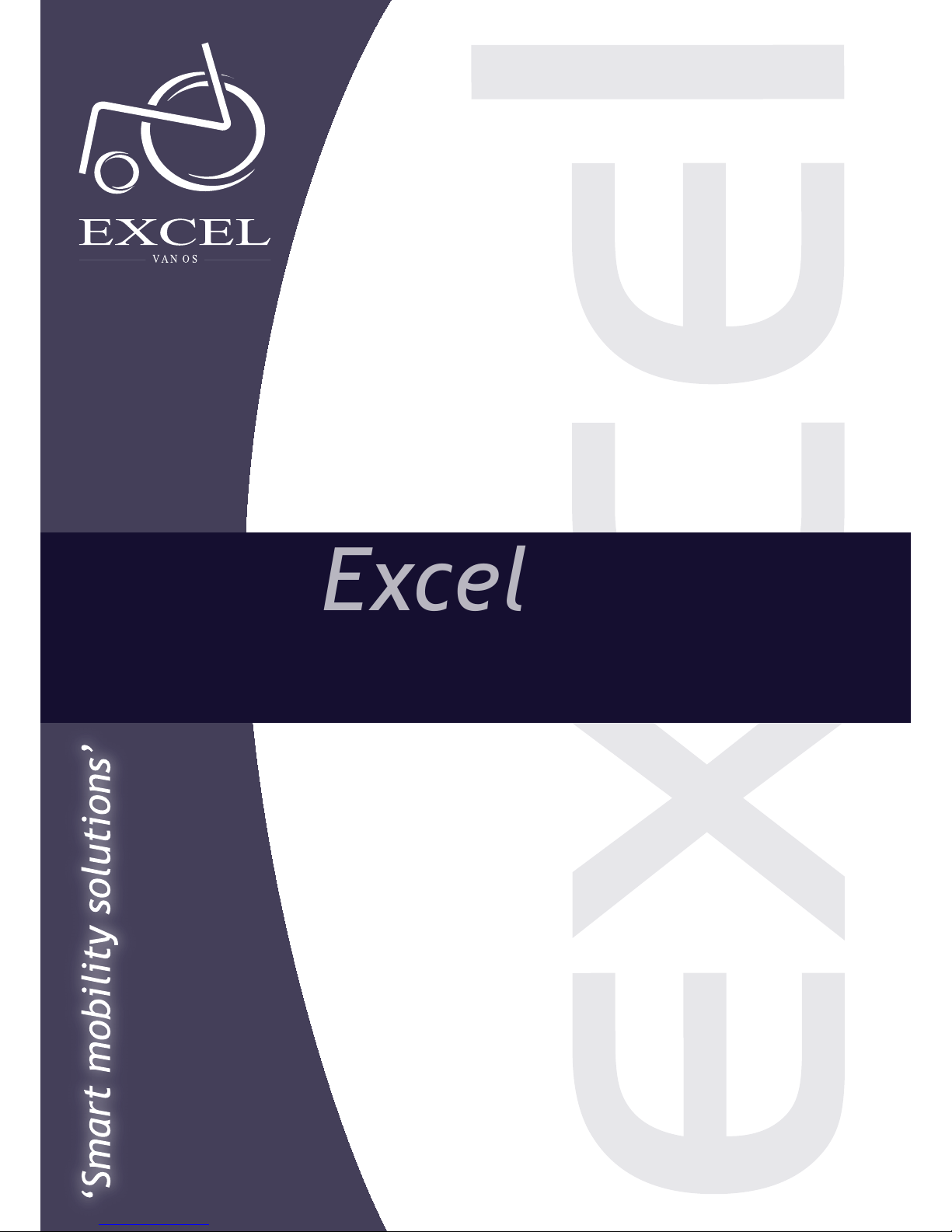
SHUTDOWN
Before you leave your power chair, press the ON/OFF push utton. The warning
lamp and voltmeter indicator will extinguish. Fold the footrest plates upward.
Make this shutdown sequence a standard procedure and a ha it. It is essential for
your personal safety.

10
MANUAL PROPEL
Picture 12
If the powerchair is to e pushed y hand, proceed as follows:
from ehind the vehicle, turn the two uncoupling levers (picture 12) of the electric
motors outward to the side, so they are pointing toward the rear wheels.
Warning:
1. Never move the uncoupling levers while the vehicle is operating with powered
device.
2. When the electric motors are disengaged, the armature rakes and the
elctromagnetic safety rakes are out of action, ensure that the powerchair is
secured with the hand- rakes when it is parked.
When normal powered operation is to e restored, return oth uncoupling levers to
normal position (picture 13).
Picture 13
Important:
The vehicle will not operate with powered drive unless oth uncoupling levers are
in normal position.

11
GETTING READY FOR PERMANENT USE
Now that you have had a good look at your rand new powerchair and taken it for a
test drive in your home and around the house, it is a solutely necessary to carry
out a attery charging procedure efore you start normal operation and take your
powerchair on its first long range outing. Read the next section carefully.
BATTERIES
The X-power 10 has two 12 Volt, 31Ah motive power atteries which are
accomodated in two attery oxes under the seat at the rear of the powerchair.
The atteries are sealed and maintenance free.
Warning:
Do not attempt to open the atteries.
Regular monitoring of the attery charge condition and timely recharging are
essential to ensure relia ility and performance or your powerchair as well as long
attery service life.
The intervals at which the atteries have to e recharged (hours travelled or
mileage covered) depend on various factors. It is not possi le to specify a generally
valid fixed date. O serve the following and you will soon esta lish a cycle in
accordance with your individual requirements and driving routine.
At full attery charge all 10 segments of the attery gauges are lit continuously.
With the progressive discharge of the atteries, successive segments will
extinguish.
When the attery charge has dropped to 4 scales, yellow light, depending on age
and condition of the atteries, you are then left with a limited driving range efore
you must recharge the atteries. To avoid this critical condition, we recommend
charging the atteries overnight whenever you have used your powerchair. It will
not only spare you unpleasant sitiuations en route, ut it will also prolong the
attery service life.
Should you ignore this warning, while the attery gauges is on red and allow the
atteries to ecome almost fully discharged, the electronic controller will
automaticly shut down the entire electrical system of the powerchair and ring it
to a halt.
Note:
While clim ing a steep gradient, you may find that the attery warning lamp egins
to flash. This does not necessarily mean that the atteries are discharges to the
critical level. Recheck the warning lamp after you reach level ground.
If during the course of the day, you have used your powerchair for more than one
hour of actual travelling time, it is recommended that you charge the atteries
overnight.The specia-design charger will switch off automatically when the

12
atteries are charged , so it is completely safe and does not use excess electricity
regardless of the time the atteries are connected to the charger.
If your powerchair remains unused for any length of time (approximately four
weeks or more), the atteries must e charged. Charge them at least once a month
to maintain their charge.
BATTERY CHARGING
The atteries of your X-power 10 are different from ordinary car atteries. Only
use the charger specifically designed for the motive power type atteries installed.
1. Always insert the charger output plug into the charging socket on the front face
of the controller. Only than connect the charger input ca le to an electrical
outlet.
2. Follow the instructions on the front panel of the charger for its operation and
the meaning of its indicators
3. The minimum time required for charging varies and depends on attery
condition and discharge level. We recommend, however, that the atteries e
charged overnight.
Picture 14
Note:
The specially designed charger ensures that excess power is not consumed
regardless of how long it is switched on and connected to the atteries.
4. On completion of the charging cycle, first disconnect the charger input from the
electrical outlet and only then disconnect the charger from the controller
socket. Do not leave the charger connected to the controller when its input
power is disconnected. This will cause the atteries to discharge.
For replacement of the atteries, contact your dealer.

13
FOOTREST REMOVAL INSTRUCTONS
Picture 15
1. Push the spring loaded steel lever (picture 15) inward
2. Swing the footrest assem ly slightly outward and lift the complete footrest
assem ly clear of the main frame
3. Installation is in reversed order of removal procedure
SIDEPLATE / ARMREST REMOVAL INSTRUCTIONS
Picture 16
1. Simply pull the side panel / armrest upward and push the spring loaded pin at
the front of the side panel (picture 16) downward until it releases the assem ly
2. Installation is in reversed order of removal procedure

14
BACKREST REMOVAL INSTRUCTIONS
Picture 17
1. Remove the two screws and nut from the ottom of the ackrest (picture 17)
and pull the ackrest upward out of the frame
2. Installation is in reversed order of removal procedure
WHEELS REMOVAL AND ASSEMBLING INSTRUCTIONS
Rear wheel:
1. Ensure that the clutch lever of the motor drive is engaged (picture 13)
2. Support of jack up the power chair under the side frame
3. Unscrew the hexagon olt and remove, together with the washer
4. Withdraw the rear wheel from the drive axle
Installation is in reversed order of removal procedure. Check that the threads of
the hexagon volt are undamaged and clean. If necessary, wipe with a clean dry
cloth. Do not use any sharp tools to clean the threads. Do not forget to slide the
washer over the olt efore it is screwed in. Tighten the olt firmly.
Front wheel:
1. Support or jack up the powerchair under the side frame
2. Use the wrench provided, remove the axle olt
3. Slede the front wheel out of the fork
4. Assem ling is in reversed order

15
TIRE INFLATION
Picture 18
1. Take out the connection adaptor from the air pump (picture 18)
2. Insert the adaptor to the pump
3. Start to inflate the tire to your desired (30~60 psi) pressure
FOLDING THE POWERCHAIR
Picture 19
The powerchair can e folded to a neat and compact size within minutes.
1. Ensure that the master socket is disconnected
2. Fold the two footrest plates upward
3. Loosen the star kno for adjustment of the controller position and slide the
controller ak as far as it will go. Tighten the star kno
4. Disconnect the attery ca le connector from the controller
5. Remove attery oxes, then remove asket
6. Take a firm hold of the seat support tu es on each side of the seat and pull
upward. The two sides will accore together to a compact stowing size
7. If the folded power powerchair is stowed of transported in a horizontal position,
place it so that the side with controller is uppermost to prevent damage to the
controller

16
GENERAL SPECIFICATION DATA
Batteries 2 x 12 Volt 31 Ah, maintenance free,
sealed gel
Speed 0 – 6,5 km/h
Range Approximately 25 km on level ground
with 91 kg occupant
Clim ing performance Up to 25% (1 in 4) on form dry
ground. Up to 20% (1 in 5) on loose
ground (gravel, loose chips, grass,
sand etc.)
Brakes Regenerative motor rakes,
(on oth rear wheels) elektromagnetic safety rakes and
parking rakes.
Seat height 52 cm
Seat width 41 – 46 cm standard, 38 – 43 cm
optional
Total width (normal) 55 – 57 – 60 – 63 cm
Total width (folded) 36 cm
Total length 106 cm
Total height 101 cm
Total weight 53 kg
Tire pressure 2-2.5 BAR (30-37 psi)
PU TIRES
No inflation necessary, 12½“ x 2½” rear wheels.
PARKING BRAKES
Wheel locks should e checked regularly to ensure grip.
The purpose of the wheel locks is to hold the powerchair in place when it is
stopped, not to slow it down when it is moving.
Always engage oth locks efore entering or exiting the powerchair.
Never stand on the footrests while entering or exiting the powerchair. Standing on
the footrests could cause the powerchair to tip over.
The owner should enter or exit the powerchair only after the power is turned off.
TURNING RADIUS
It is very important, especially when travelling on inclines, to reduce your speed
with the control lever efore making a sharp turn. Never try to turn the powerchair
suddenly while travelling at full speed.
Your powerchair should not e operated on streets except when using the
crosswalks. Operate your powerchair with extreme caution.

17
ANTI-TIPPERS
Anti-tippers are standard with the X-power 10. Replacements for these parts are
availa le through your authorized dealer. Anti-tipper prevent the powerchair from
tipping ackwards.
PARTS
Special high strength fasteners are used on the powerchair. Replacements for these
parts should e ordered through an authorized dealer.
Warnings:
Never stand on the footrests as it may cause the powerchair to tip over.
Never lift the powerchair y the footrests. The footrests are remova le and lifting
the powerchair y the footrests could cause damage to the powerchair or possi le
injury to the owner.
Never connect the attery charger to the main supply until after you have
connected it to the powerchair.
It is important to develop safe techniques efore attempting to negtiote o stacles
such as cur s, ramps and inlines. Never try to go up a steep incline without
assistance. Avoid uneven and hilly terrain as the powerchair may tip over. Avoid
grades steeper than 10% (1 foot rise in a ten foot distance) without assistance.
Control your speed carefully when traveling downhill. Slow speeds should e used
when travelling on downgrades.
Do not use the ON/OFF switch to turn off the power to the powerchair while it is
moving. This will cause the powerchair to come to an a rupt stop and may cause
injury to the user or damage to the chair.
Many powerchair controllers have een affected y high power radio transmitters,
such as CB radios and cellular telephones. If any of these devices are eing used
near your powerchair, you should use caution in operation. If loss of control occurs,
shut off your powerchair immediately and leave it off until the interfering devices
are no longer operating.
The user should e trained y a healthcare professional to assure safe operation of
the powerchair during the performance of daily activities.
WEIGHT LIMIT OF THE POWERCHAIR
Maximum weight limit should not exceed 100 kg.

18
CONTROLLER
The electronic controller is normally installed on the right side of the powerchair,
elow the armrest / side panel. On the rear face of the controller are two
connectors; the lower one is for the master socket from the two motors and the
atteries, the upper one is for the ca le loom form the joystick ox. For trou le
free operation, it is important to ensure that all these connectors are firmly seated
at all times. Refer to the trou leshooting guide.
On the forward face of the controller are two vacant connectors. The upper
connector is for the attery charger. The lower connector is for connecting
specialized equipment for programming at your dealers or at the factory. Do not
tamper with this connector and protect it from dirt and damage. Apart from
assuring that the connectors are properly seated, do not interfere with the
controller in any way.
BATTERY BOXES
On the top right side of the rear attery ox, you will see the reset utton of a
circuit reaker. This utton must always e pressed in, otherwise the powerchair
will not operate. Refer to the trou leshooting guide. Also on the attery oxes are
ca les with connectors for connecting the atteries together and to connect
atteries to the controller ox. To remove the attery oxes (when you want to
fold the powerchair), you must first disconnect these connectors from the attery
oxes.
MAINTENANCE
There are no specific maintenance requirements for the joystick and the
controller, ut the service life of the equipment will e extended if you ovserve
the following:
the joystick ox and the controller are splash proof ut should e protected from
excessive spillage of liquid. Do not expose to direct heat (from an electric heater
for example). Check that the ru er oot on the joystick and switch cover are in
good condition and show no holes or cracks.

19
PROBLEMS AND SOLUTIONS
Na ure of faul
Proble
m
Ac ion
1.
Powerchair does not
drive, and lamp does not
work
a.
Main plug not inserted
. ON / OFF push utton
in OFF position
c. Batteries discharged to
low level
d. Loose plug connection
at controller or attery
a.
Connect plug properly
. Push the ON / OFF
utton
c. Recharge the atteries
d. Press plugs firmly into
their sockets
2.
Powerchair does not
drive, ut lamp does work
a.
Drive motor is in
freewheel
. Fault in controller
electronics
a.
Reset uncoupling
lever
(s)
. Consult dealer
3.
Lamp flashing quickly
(2
times per second)
a.
Motor plug is loose
. Battery status is very
low
c. Fault in controller
a.
Press plugs firmly
. Recharge the atteries
c. Consult your dealer
Impor an
In all cases of an electrical fault, check that the circuit reaker (located on the rear
attery ox) is pressed in. If it has een tripped it must e pressed. If the reset
utton comes out again, even after the suspected cause of the fault has een
corrected, consult your dealer.
Copyright © 2004 Van Os Medical B.V.
Van Os Medical B.V.
Nijverheidsweg 4-6
Tel. +31 (0) 167 57 3020
Fax +31 (0) 167 57 3381
www.vanosmedical.com
info@vanosmedical.com
This manual suits for next models
2
Table of contents
Other Excel Wheelchair manuals