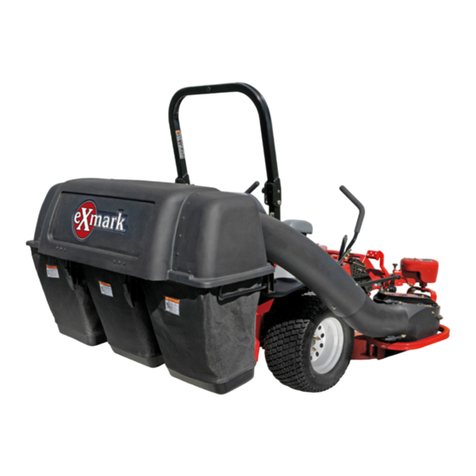
Exmark 126-7882 User manual
Other Exmark Lawn And Garden Equipment manuals

Exmark
Exmark Quest Bagger Manual
Exmark
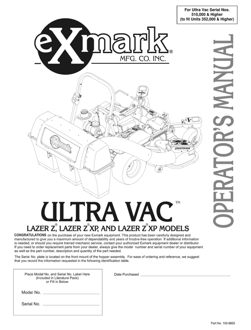
Exmark LZUV52 User manual

Exmark
Exmark STANDON User manual
Exmark
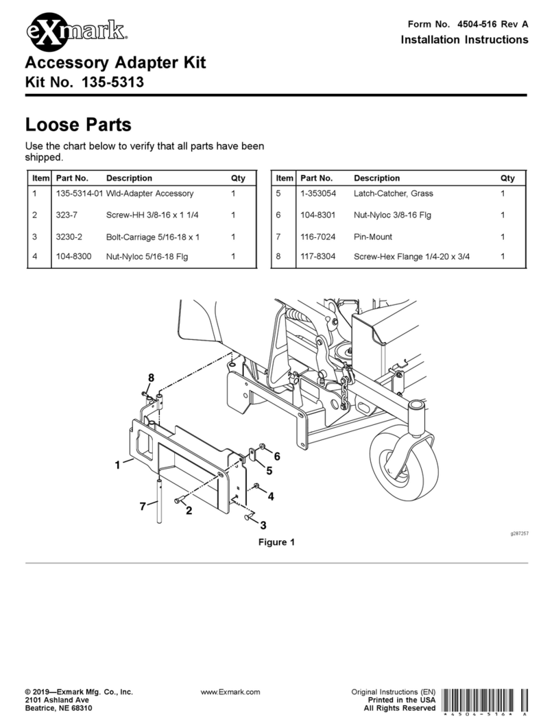
Exmark 135-5313 User manual

Exmark
Exmark STANDON Series User manual
Exmark
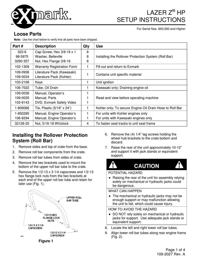
Exmark Lazer Z HP Manual

Exmark
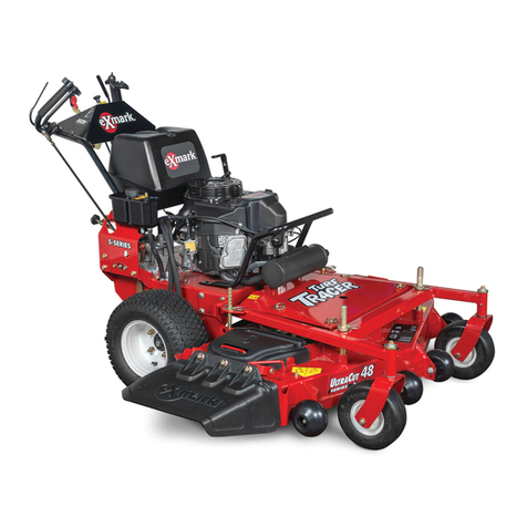
Exmark Z Turf Equipment Z-SWEEP User manual
Exmark
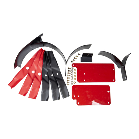
Exmark TURF TRACER S-SERIES Operators Manual
Exmark
Exmark MK443Q User manual

Exmark
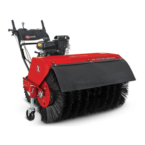
Exmark SAR481KA30 User manual
Exmark
Exmark BRS270CKC36000 User manual

Exmark
Exmark QUEST User manual
Exmark
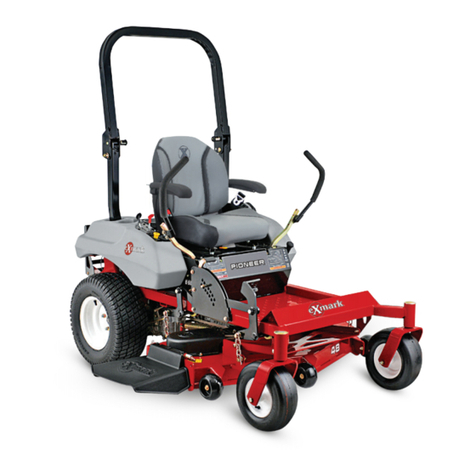
Exmark Pioneer E Series Manual
Exmark
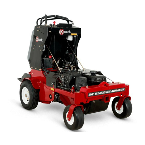
Exmark ARX440CKC24000 User manual
Exmark
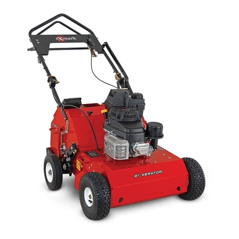
Exmark ARS180KA21 User manual
Exmark
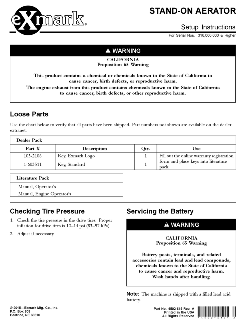
Exmark 4502-619 Manual
Exmark
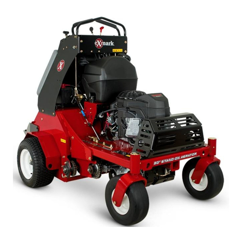
Exmark ARX541CKA30000 Manual
Exmark
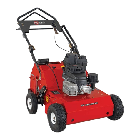
Exmark ARS180CKA21000 Manual
Exmark
Exmark Quest 126-7508 User manual
Exmark
Exmark TURF TRACER S Series Manual
Popular Lawn And Garden Equipment manuals by other brands

Vertex
Vertex 1/3 HP Maintenance instructions

GHE
GHE AeroFlo 80 manual

Millcreek
Millcreek 406 Operator's manual

Land Pride
Land Pride Post Hole Diggers HD25 Operator's manual

Yazoo/Kees
Yazoo/Kees Z9 Commercial Collection System Z9A Operator's & parts manual

Premier designs
Premier designs WindGarden 26829 Assembly instructions

AQUA FLOW
AQUA FLOW PNRAD instructions

Tru-Turf
Tru-Turf RB48-11A Golf Green Roller Original instruction manual

BIOGROD
BIOGROD 730710 user manual

Land Pride
Land Pride RCF2784 Operator's manual

Makita
Makita UM110D instruction manual

BOERBOEL
BOERBOEL Standard Floating Bar Gravity Latch installation instructions
