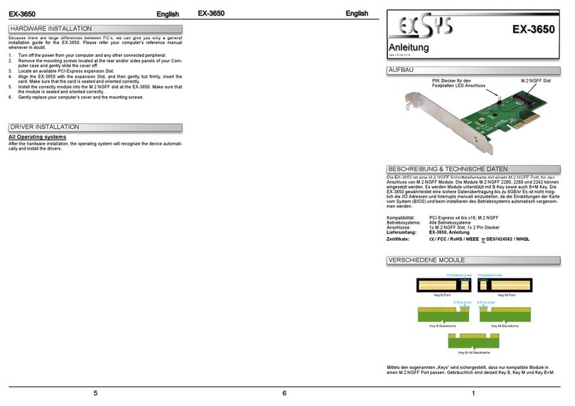
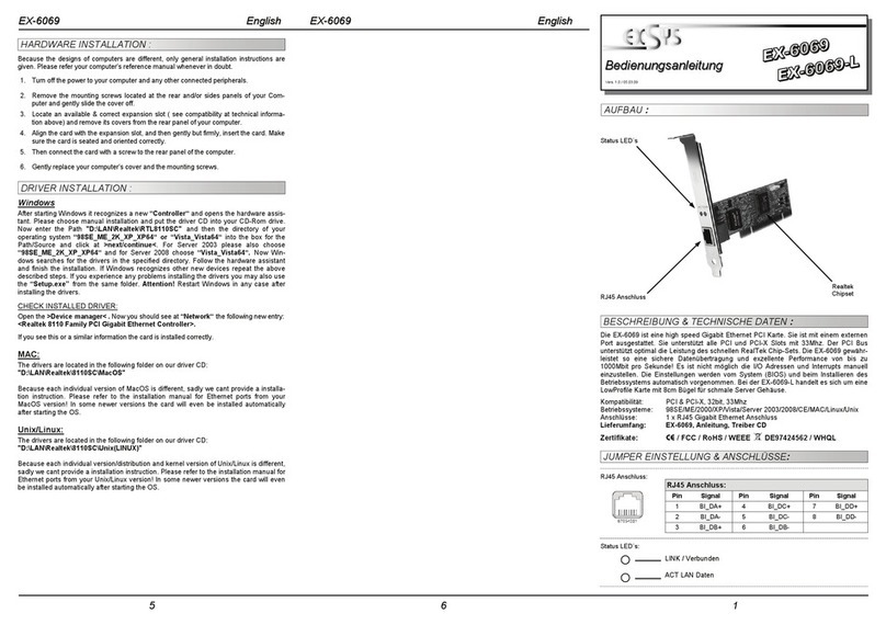
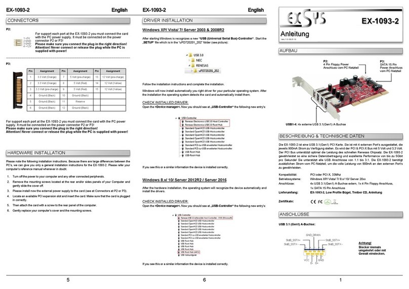
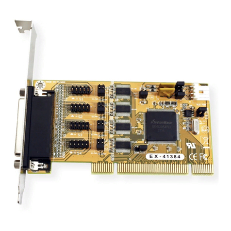
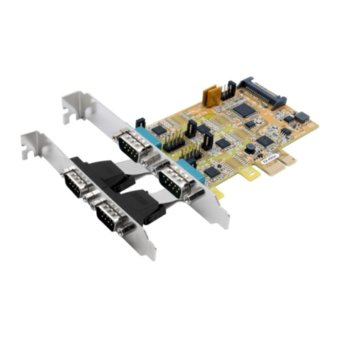
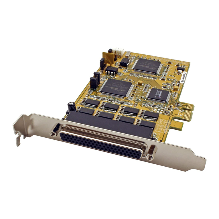
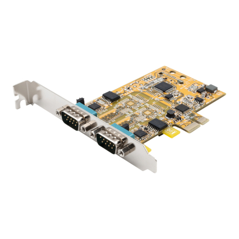
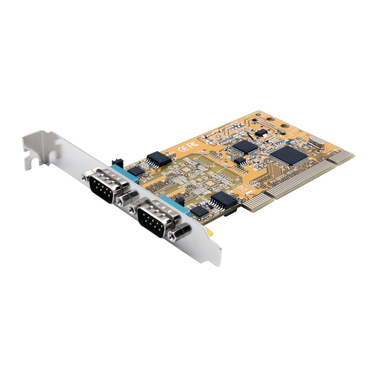
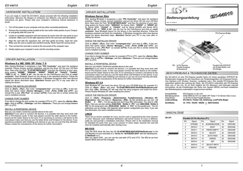
Exsys EX-44384 User manual

Anleitung
Vers. 1.0 / 01.08.18
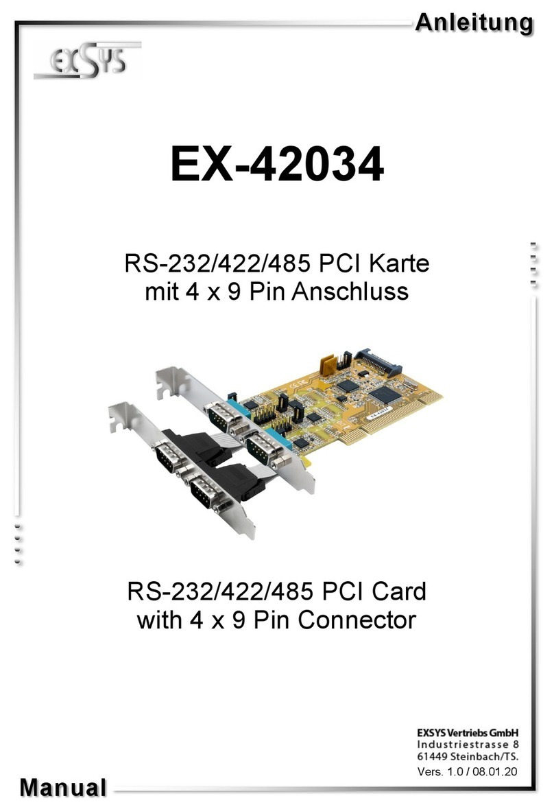
EX-44384
RS-232 PCI-e Karte
mit 4 x 9 Pin Anschluss
Manual
RS-232 PCI-e Car
with 4 x 9 Pin Connector

2
EX-44384
1. Beschreibung······················································································ 3
2. Lieferumfang ······················································································ 3
3. Aufbau & Anschlüsse ·········································································4-5
3.1 Aufbau······································································································ 4
3.2 Anschlüsse······························································································4-5
4. Jumper Einstellung ············································································5-6
5. Har ware Installation············································································ 7
6. Treiber Installation ·············································································7-9
7. Technische Daten················································································ 9
1. Description ························································································10
2. Extent of Delivery ···············································································10
3. Layout & Connections····································································· 11-12
3.1 Layout ·····································································································11
3.2 Connections ························································································ 11-12
4. Jumper Settings ············································································ 12-13
5. Har ware Installation···········································································14
6. Driver Information ·········································································· 14-16
7. Technical Information ··········································································16
Inhaltsverzeichnis
Index
© Copyright 2018 by EXSYS Vertriebs GmbH. All Rights Reserve

3
EX-44384 Deutsch
Die EX-44384 ist eine PCI-Express serielle RS-232 Karte mit 4 seriellen FIFO 16C550
Ports, für en Anschluss von High-Spee seriellen RS-232 Peripherie Geräten (z.B.
Terminal, Mo em, Plotter usw.). Der serielle PCI-Express Bus unterstützt abei optimal
ie Leistung es schnellen 16C550 Chipset mit 256byte FIFO Cache. Die Karte ge-
währleistet so eine sichere Datenübertragung un exzellente Performance von bis zu
921,6KBau /s! Sie unterstützt alle PCI-Express Slots von x1 bis x16. Es ist nicht mög-
lich ie I/O A ressen un Interrupts manuell einzustellen, a ie Einstellungen er Kar-
te vom System (BIOS) un vom Betriebssystem automatisch vorgenommen wer en.
Die EX-44384 bietet Ihnen ie Möglichkeit, +5V un +12V auf Pin 1 un Pin 9 er seriel-
len Anschlüsse zur Verfügung zu stellen. Es wir zusätzlich für en Einbau in schmale
Computergehäuse ein 8 cm Low Profile Slot-Bügel mitgeliefert.
Merkmale:
• PCI-Express x1 bis x16
• 300Bau bis 921,6KBau /s
• Unterstützt wir RS-232
• Unterstützt: Win ows NT 4.0/ 9x/ 2000/ XP/ Vista/ 7/ 8.x/ 10/ Server 20xx/ Linux
• Zertifiziert f r
Bevor Sie en EX-44384 an Ihren PC anschließen, überprüfen Sie bitte zuerst en In-
halt er Lieferung:
• EX-44384
• Oktopus Kabel
• Low Profile Bügel
• Treiber CD
• Anleitung
1. Beschreibung
2. Lieferumfang
© Copyright 2018 by EXSYS Vertriebs GmbH. All Rights Reserve

4
Deutsch EX-44384
3.1 Aufbau
3. Aufbau & Anschl sse
© Copyright 2018 by EXSYS Vertriebs GmbH. All Rights Reserve
JP2: Nur für Testzwecke
(Nicht verän ern!)
JP3: PME Ein- / Ausschalten JP1: Jumper für ie Stromquelle
(Netzteil o er PCI-Express Bus) J2: Anschluss für Strom
vom PC Netzteil
S1~S4_PWR:
Power auf Pin 1
o er Pin 9 es
RS-232 Stecker
Ein/Aus
S1~S4-PH:
Interner serieller Anschluss
S1-S4: 44 Pin Stecker zu 4 x 9Pin
Serieller Anschluss
3.2 Anschl sse
DB9 (EX-44384) DB9 (Endgerät)
1 DCD 1 DCD
2 RXD 2 RXD
3 TXD 3 TXD
4 DTR 4 DTR
5 GND 5 GND
6 DSR 6 DSR
7 RTS 7 RTS
8 CTS 8 CTS
S1-S4:

5
EX-44384 Deutsch
3. Aufbau & Anschl sse
© Copyright 2018 by EXSYS Vertriebs GmbH. All Rights Reserve
4. Jumper Einstellungen
3.2 Anschl sse
JP3:
DIS =Die Funktion PME ist ausgeschaltet. (Werkseinstellung)
ENA = Die Funktion PME ist eingeschaltet. Der PC kann nun urch ie
Seriellen Ports er EX-44384 aktiviert wer en.
Dieser sollte aber bei Stan ar Anwen ungen nicht verstellt wer en.
Es gibt 2 verschie ene Spannungsquellen (Mainboar & PC-Netzteil).
(Bei Jumper Einstellung X5 / X12 muss er Stromanschluss (J2) mit em
PC-Netzteil verbun en wer en!)
X5 =5Volt vom PC-Netzteil (Werkseinstellung)
X12 =12Volt vom PC-Netzteil
I12 =12Volt vom Mainboar (Werkseinstellung)
I12 X12 X5
JP1:
DIS
J2:
+5V
GND
GND
+12V
Für AUX Einstellung (JP1) muss J2 mit em PC Netzteil
verbun en wer en! Sonst wir ie Karte nicht mit Strom
versorgt.
ENA

6
Deutsch EX-44384
© Copyright 2018 by EXSYS Vertriebs GmbH. All Rights Reserve
4. Jumper Einstellungen
S1~S4_PWR:
+5V auf Pin1
+12V auf Pin1
+5V auf Pin9
+12V auf Pin9
Kein Power auf Pin1 o er Pin9
Pin1= DCD
Pin9= RI
(Werkseinstellung)
S1~S4_PWR Jumper Einstellung
DCD RI
5V P#1 12V P#9 5V
DCD RI
5V P#1 12V P#9 5V
DCD RI
5V P#1 12V P#9 5V
DCD RI
5V P#1 12V P#9 5V
DCD RI
5V P#1 12V P#9 5V

7
EX-44384 Deutsch
© Copyright 2018 by EXSYS Vertriebs GmbH. All Rights Reserve
5. Hardware Installation
Wenn Sie ie Karte installieren, beachten Sie bitte ie folgen en Hinweise. Da es große
Unterschie e zwischen PC‘s gibt, können wir Ihnen nur eine generelle Anleitung zum
Einbau geben. Bei Unklarheiten halten Sie sich bitte an ie Be ienungsanleitung Ihres
Computersystems.
1. Schalten Sie Ihren Rechner un alle angeschlossenen Peripheriegeräte aus un zie-
hen Sie bei allen Geräten en Netzstecker.
2. Lösen Sie ie Schrauben es Gehäuses auf er Rückseite Ihres Computers un ent-
fernen Sie vorsichtig as Gehäuse.
3. Suchen Sie einen freien Steckplatz un entfernen Sie as Slot Blech, stecken Sie ie
Karte vorsichtig in en ausgewählten Steckplatz ein. Stellen Sie sicher as es sich um
en richtigen Steckplatz han elt! (siehe Kompatibilität unter technische Daten)
4. Beachten Sie as ie Karte korrekt eingesteckt wir un as kein Kurzschluss ent-
steht. Wen en Sie bitte keine Gewalt an um ie Karte einzustecken!
5. Danach befestigen Sie ie Karte bitte mit einer Schraube am Gehäuse.
6. Jetzt können Sie as Computergehäuse mit en Schrauben wie er schließen.
6. Treiber Installation
Windows
Nach Abschluss er Har wareinstallation erkennt as Betriebssystem automatisch ie
Karte un installiert iese! Falls ie Treiber nicht automatisch installiert wer en sollten,
legen Sie nun ie Treiber CD in Ihr CD-ROM Laufwerk (z.B. Laufwerk D:) ein un öff-
nen Sie en Or ner „IO/SYSTEMBASE/DRIVERS/PCI(PCIe Bridge)“. Nun wählen Sie
en Or ner Ihres Betriebssystems aus un installieren Sie ie Treiber (siehe Abbil-
ung). Folgen Sie en Installationsanweisungen un schließen Sie ie Installation ab.
Wichtig! Starten Sie Ihren PC nach er Installation neu.

8
Deutsch EX-44384
© Copyright 2018 by EXSYS Vertriebs GmbH. All Rights Reserve
6. Treiber Installation
ÜBERPRÜFEN DES INSTALLIERTEN TREIBER
Öffnen Sie en >Geräte-Manager<. Jetzt müssten Sie unter „Anschl sse (COM &
LPT)“ un unter „Multifunktionsadapter“ folgen e Einträge sehen:
Sin iese o er ähnliche Einträge vorhan en, ist ie Karte richtig installiert.
ÄNDERN DER PORT NUMMER
Sie können auch ie Port Nummer än ern, in em Sie im Gerätemanager z.B. „COM3“
„Anschlusseinstellung“ un „Erweitert“ öffnen. Nun können Sie ann zwischen COM3
bis COM256 wählen!
Windows Server 20xx
Nach Abschluss er Har wareinstallation erkennt as Betriebssystem automatisch ie
Karte un installiert iese! Falls ie Treiber nicht automatisch installiert wer en sollten,
legen Sie nun ie Treiber CD in Ihr CD-ROM Laufwerk (z.B. Laufwerk D:) ein un öff-
nen Sie en Or ner „IO/SYSTEMBASE/DRIVERS/PCI(PCIe Bridge)“. Nun wählen Sie
en Or ner Ihres Betriebssystems aus un installieren Sie ie Treiber (siehe Abbil-
ung). Folgen Sie en Installationsanweisungen un schließen Sie ie Installation ab.
Wichtig! Starten Sie Ihren PC nach er Installation neu.
Es wer en folgen e Treiber für ie Server Betriebssysteme installiert:
Win ows Server 2003 =XP Treiber
Win ows Server 2008 =VISTA Treiber
Win ows Server 2008R2 =Win ows 7 Treiber
Win ows Server 2012 =Win ows 8.x Treiber
Win ows Server 2012R2 =Win ows 10 Treiber
ÜBERPRÜFEN DER INSTALLIERTEN TREIBER
Öffnen Sie en >Geräte-Manager<. Jetzt müssten Sie unter „Anschl sse (COM &
LPT)“ un unter „Multifunktionsadapter“ folgen e Einträge sehen:
Sin iese o er ähnliche Einträge vorhan en, ist ie Karte richtig installiert.

9
EX-44384 Deutsch
7. Technische Daten
Chipsatz: SystemBase SB16C1054PCI
Datentransfer-Rate: 300Bau bis 921,6KBau
Anschl sse: 4x 9 Pin D-Sub serieller Stecker, 4x interner 10 Pin
Pfostenstecker, 1x 4 Pin Floppy Stromanschluss
Hardwaresystem: PCI-Express x1 bis x16
Betriebssystem: Win ows NT 4.0/ 9x/ 2000/ XP/ Vista/ 7/ 8.x/ 10/
Server 20xx/ Linux
Betriebstemperatur: 0°C bis 55° Celsius
Lagertemperatur: -40°C bis 75° Celsius
Rel. Luftfeuchtigkeit: 5% bis 95%
Stromversorgung: 5V o er 12V vom PC-Netzteil o er 12V vom Mainboar
Abmessung: 89,00 x 66,00 mm
Gewicht: 800g
© Copyright 2018 by EXSYS Vertriebs GmbH. All Rights Reserve
6. Treiber Installation
ÄNDERN DER PORT NUMMER
Sie können auch ie Port Nummer än ern, in em Sie im Gerätemanager z.B. „COM3“
„Anschlusseinstellung“ un „Erweitert“ öffnen. Nun können Sie ann zwischen COM3
bis COM256 wählen!
Linux / SCO Unix
Die Treiber für Linux / SCO Unix befin en sich in folgen em Verzeichnis:
"IO/SYSTEMBASE/DRIVERS/PCI(PCIe Bridge)/SCO"
Da sich ie einzelnen Distributionen un Kernelversionen sehr voneinan er unterschei-
en, können wir Ihnen lei er keine Installationsanweisung zu Verfügung stellen. Bitte
halten Sie sich an ie Installationsanweisung für Stan ar I/O Ports Ihrer Linux/Unix
Version. In einigen neueren Versionen, wir ie Karte sogar automatisch beim Start
Installiert.

10
Deutsch EX-44384
The EX-44384 is a plug & play high-spee serial RS-232 expansion car for the PCI-
Express Bus. It provi es four 9 pin high spee RS-232 serial ports. It uses ata transfer
rates up to 115.2Kbau /s. The car esign utilizes the 16C550 UART with 256byte buff-
er, which incorporates the latest in high spee interface technology. In combination with
the fast PCI-Express bus it provi es a secure an very high ata transfer on each sin-
gle port. It supports all PCI-Express slots x1 to x16. It is not possible to change the a -
ress or IRQ settings manually, they will be obtaine automatically by the system
(BIOS) an operating system. The EX-44384 allows you to provi e + 5V an + 12V on
pin 1 an pin 9 of the serial ports. There is a itionally a 8 cm low profile slot bracket for
installation in small computer housing.
Features:
• PCI-Express x1 to x16
• 300Bau bis 921,6KBau /s
• Support RS-232
• Supports: Win ows NT 4.0/ 9x/ 2000/ XP/ Vista/ 7/ 8.x/ 10/ Server 20xx/ Linux
• Certificate for
Before you connect the EX-44384 to your PC, you shoul first check the contents of the
elivery:
• EX-44384
• Octopus Cable
• Low Profile Bracket
• Driver CD
• Manual
1. Description
2. Extent of Delivery
© Copyright 2018 by EXSYS Vertriebs GmbH. All Rights Reserve

11
EX-44384 English
© Copyright 2018 by EXSYS Vertriebs GmbH. All Rights Reserve
3.1 Layout
3. Layout & Connections
JP2: Only for Tests
(Do not change!)
JP3: PME On / Off JP1: Select the power over Power
Supply or PCI-Express Bus J2: Connector for PC
Power Supply
S1~S4_PWR:
Power to Pin 1 or
Pin 9 On / Off
S1~S4-PH:
Internal serial hea ers
S1-S4: 44 pin connector to
4 x 9Pin serial connectors
3.2 Connections
DB9 (EX-44384) DB9 (Device)
1 DCD 1 DCD
2 RXD 2 RXD
3 TXD 3 TXD
4 DTR 4 DTR
5 GND 5 GND
6 DSR 6 DSR
7 RTS 7 RTS
8 CTS 8 CTS
S1-S4:

12
English EX-44384
© Copyright 2018 by EXSYS Vertriebs GmbH. All Rights Reserve
3. Layout & Connections
4. Jumper Settings
3.2 Connections
JP3:
DIS =The function PME is isable. (Factory Setting)
ENA = The function PME is enable. Now the car can be activate
the computer through the serial ports.
But this shoul not be a juste for stan ar applications.
There are two ifferent voltage sources (Mainboar & Power Supply).
(If the jumper JP1 set to X5 / X12 then the power connector J2 must be
connecte with the PC power supply)
X5 =5Volt from Power Supply (Factory Setting)
X12 =12Volt from Power Supply
I12 =12Volt from Mainboar (Factory Setting)
I12 X12 X5
JP1:
DIS
J2:
+5V
GND
GND
+12V
For aux power (JP1), J2 must be connecte to pc power
supply! If not the car won’t work.
ENA

13
EX-44384 English
© Copyright 2018 by EXSYS Vertriebs GmbH. All Rights Reserve
4. Jumper Settings
S1~S4_PWR:
+5V to Pin1
+12V to Pin1
+5V to Pin9
+12V to Pin9
No Power Supplie on Pin1 or Pin9
Pin1= DCD
Pin9= RI
(Factory Setting)
S1~S4_PWR Jumper Setting
DCD RI
5V P#1 12V P#9 5V
DCD RI
5V P#1 12V P#9 5V
DCD RI
5V P#1 12V P#9 5V
DCD RI
5V P#1 12V P#9 5V
DCD RI
5V P#1 12V P#9 5V

14
English EX-44384
© Copyright 2018 by EXSYS Vertriebs GmbH. All Rights Reserve
5. Hardware Installation
If you are rea y with the jumper settings, please procee with the following installation
instructions. Because there are large ifferences between PC’s, we can give you only a
general installation gui e. Please refer to your computer’s reference manual whenever
in oubt.
1. Turn off the power to your computer an any other connecte peripherals.
2. Remove the mounting screws locate at the rear an / or si es panels of your Comput-
er an gently sli e the cover off.
3. Locate an available expansion slot an remove its covers from the rear panel of your
computer. Make sure it is the right expansion slot for the car (see car escription)
4. Align the car with the expansion slot, an then gently but firmly, insert the car . Make
sure the car is seate an oriente correctly. Never insert the car by force!
5. Then connect the car with a screw to the rear panel of the computer case.
6. Gently replace your computer’s cover an the mounting screws.
6. Driver Installation
Windows
After completing the har ware installation, the operating system will automatically the
car an install this! If the river shoul not be installe automatically, insert the river
CD into you CD-ROM rive (eg rive D:) an then open the fol er „IO/SYSTEMBASE/
DRIVERS/PCI(PCIe Bridge)“. Please select the fol er with your operating system an
install the river (see Picture). Follow the har ware assistant an finish the installation.
Important! Restart your PC in any case after installing the rivers.

15
EX-44384 English
© Copyright 2018 by EXSYS Vertriebs GmbH. All Rights Reserve
6. Driver Installation
CHECK INSTALLED DRIVER
Open the >Device manager<. Now you shoul see at „Ports (COM & LPT)“ an at
„Multifunction Adapter“ the following new entry's:
If you see this or a similar information the evice is installe correctly.
CHANGE PORT NUMBER
If you like to change the port number for example COM3 to COM5, open the „Device
Manager” click at „COM3”, „Settings” an then „Advance”. There you can change be-
tween COM3 till COM256.
Windows Server 20xx
After completing the har ware installation, the operating system will automatically the
car an install this! If the river shoul not be installe automatically, insert the river
CD into you CD-ROM rive (eg rive D:) an then open the fol er „IO/SYSTEMBASE/
DRIVERS/PCI(PCIe Bridge)“. Please select the fol er with your operating system an
install the river (see Picture). Follow the har ware assistant an finish the installation.
Important! Restart your PC in any case after installing the rivers.
Use the following river for the following Win ows Server Version.
Win ows Server 2003 =XP Driver
Win ows Server 2008 =VISTA Driver
Win ows Server 2008R2 =Win ows 7 Driver
Win ows Server 2012 =Win ows 8.x Driver
Win ows Server 2012R2 =Win ows 10 Driver
CHECK INSTALLED DRIVER
Open the >Device manager<. Now you shoul see at „Ports (COM & LPT)“ an at
„Multifunction Adapter“ the following new entry's:
If you see this or a similar information the evice is installe correctly.

16
English EX-44384
© Copyright 2018 by EXSYS Vertriebs GmbH. All Rights Reserve
6. Driver Installation
CHANGE PORT NUMBER
If you like to change the port number for example COM3 to COM5, open the „Device
Manager” click at „COM3”, „Settings” an then „Advance”. There you can change be-
tween COM3 till COM256.
Linux / SCO Unix
The rivers are locate in the following fol er on our river CD:
"IO/SYSTEMBASE/DRIVERS/PCI(PCIe Bridge)/SCO"
Because each in ivi ual istribution an kernel version of Linux is ifferent, sa ly we
cant provi e a installation instruction. Please refer to the installation manual for stan -
ar IO ports from your Unix/Linux version! In some newer versions of Linux the car will
even be installe automatically after starting Linux.
7. Technical Information
Chip-Set: SystemBase SB16C1054PCI
Data Transfer Rate: 300Bau to 921,6KBau
Connectors: 4x 9 Pin D-Sub Serial Connector, 4x Internal 10 Pin
Serial Hea er, 1x 4 Pin Floppy Power Connector
Hardware System: PCI-Express x1 to x16
Operating System: Win ows NT 4.0/ 9x/ 2000/ XP/ Vista/ 7/ 8.x/ 10/
Server 20xx/ Linux
Operating Temperature: 0°C to 55°C (32°F to 132°F)
Storage Temperature: -40°C to 75°C (-40°F to 167°F)
Rel. Humidity: 5% to 95%
Power: 5V or 12V from PC Power Supply or 12V from Mainboar
Size: 89,00 x 66,00 mm
Weight: 800g

Table of contents
Languages:
Other Exsys PCI Card manuals

Exsys
Exsys EX-42062 User manual

Exsys
Exsys EX-1083 User manual

Exsys
Exsys EX-6072PoE User manual

Exsys
Exsys EX-41054 User manual

Exsys
Exsys Ex-1083 User manual

Exsys
Exsys EX-S91002 User manual

Exsys
Exsys EX-11087 User manual

Exsys
Exsys EX-1093-2 User manual

Exsys
Exsys EX-60112 User manual

Exsys
Exsys EX-42372 User manual

Exsys
Exsys EX-6069 User manual

Exsys
Exsys EX-43063 User manual

Exsys
Exsys EX-12001-2 User manual

Exsys
Exsys EX-42032IS User manual

Exsys
Exsys EX-44352IS-4K User manual

Exsys
Exsys EX-6410 User manual

Exsys
Exsys EX-3516 Reference manual

Exsys
Exsys EX-3517R User manual

Exsys
Exsys EX-1072 User manual

Exsys
Exsys EX-11072 User manual