6
External visual inspection may reveal cracks or defects, if you notice them please
refer immediately to an EXT service point or EXT directly.
The product warranty shall only apply if product has been operated and maintained
in accordance with reccomendations in this manual.
An improperly installed fork can be extremely dangerous. We recommend to have it
installed by a qualied mechanic.
If your riding weight is more than 90kg/188lbs inspection must be more frequent.
Following the scheduled inspections allows you to have a functional and safe fork.
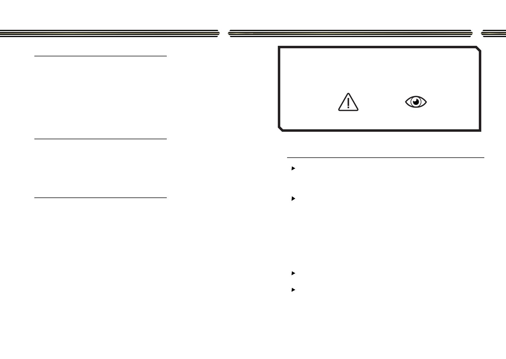
NOTE WARNING
Read and ensure you have understood
the information in this manual and other
technical documents related to this pro-
duct before using this fork. This manual,
as for others EXT manuals, is periodically
improved and updated. Visit our website
or contact us to get the most updated
one.
ExtremeBiomec Srl can not be hold
responsible for any damage to the
product, vehicle, other property or injury
to persons.
Always use EXT Racing Shox original
parts. Use of other parts or self built
ones void warranty and could cause a
structural failure.
If the shock absorber function is irregular
or if you notice any leakage, stop riding
immediately and return the product to an
EXT authorized center.
The product warranty shall only apply if
product has been operated and maintained
in accordance with recommendations in
this manual.
An improperly installed fork can be
extremely dangerous.
We recommend to have them installed by
a qualied mechanic.
Before disassembly or service always
remove gas pressure.
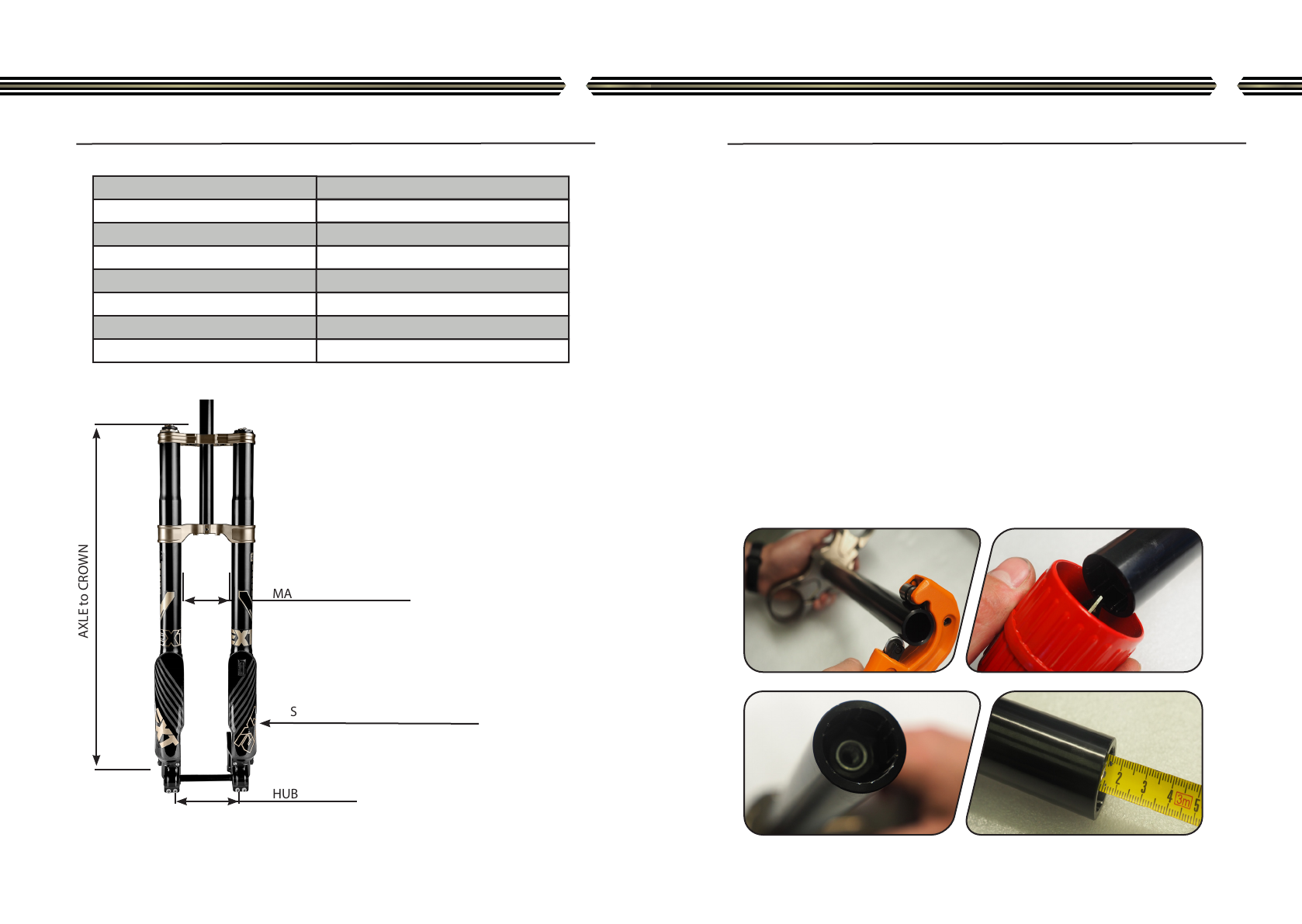
Never use more than 30 mm of spacers
height under the steerer stem, not
following this can cause the steerer tube
to fail prematurely, causing a loss of
control resulting in SERIOUS INJURY OR
DEATH.
WARRANTY
Extreme Biomec Srl, owner of EXT Racing Shox, an italian limited-liability company
based in Viale del Lavoro 66/68, 36021 Barbarano Mossano, Vicenza, Italy, applies
the following limited warranty conditions to all products.
7
LIMITED TWO (2) YEARS WARRANTY
WARRANTY EXCLUSION
DAMAGE
DISCLAIMER
Ext guarantees their damper systems are free from defects for the period of two (2)
years from date of purchase, according to 99/44/EC decree.
Invoice, documents of transport or receipt are proof of warranty start date, and it’s
mandatory they are presented to EXT for every warranty service required.
In case of a warranty claim, the purchaser can return the product to Ext or to an
authorized dealer, presenting the requested proof of purchase within 2 years period
of warranty cover, and specifying the nature of the shock absorber failure and
warranty claim.
The warranty applies only to products whose use, installation, maintenance and re-
pair have been carried out in compliance with this manual, as well as with the specic
information and technical literature provided by Extreme Biomec. This warranty does
not cover defects like: crash damage, alterations, neglect, improper use, abuse,
incorrect use, improper assembly, improper service, improper xings, use of non EXT
spare parts, modications not allowed unless specically authorised by EXT in written
form.
This warranty does not cover parts subject to wear like hydraulic seals, o-ring
seals, sliding bushing, oil, dust seals and oil seals.
This warranty will be immediately voided in case of removal or tampering of
serial numbers or they identifying marks.
The fork is not covered by warranty if it is bent or show signs of excessive force, also
as a result of use on dirt bikes that produce a maximum of superior
power at 7 KW.
Extreme Biomec Srl WILL NOT ASSUME ANY RESPONSIBILITY FOR DAMAGE TO
PERSON OR THINGS RESULTING FROM PRODUCT USE.
In some countries this clause is not accepted, this limitation could not be applied to
your country.
This warranty contract is the one and only way for customers to raise a claim on EXT
products, No EXT dealer, agent, distributor or employee can modify, extend or amplify
this warranty.