14
191816 17151412 1310 118 96 74 52 31
OPEN A
STOP
LOOP 1
LOOP 2
LOOP 2
LOOP 1
CLOSE
FSW
EMERGENCY
OUT 1
OUT 2
OUT 4
OUT 3
GND
GND
GND
+24 V
+24 V
OUT 3
J1
191816 17151412 1310 118 96 74 52 31
OPEN A
STOP
LOOP 1
LOOP 2
LOOP 2
LOOP 1
CLOSE
FSW
EMERGENCY
OUT 1
OUT 2
OUT 4
OUT 3
GND
GND
GND
+24 V
+24 V
OUT 3
J1
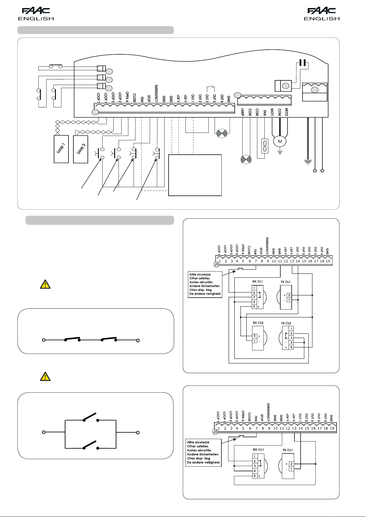
4.2. J1 TERMINAL-BOARD - ACCESSORIES (FIG.2)
LOOP 1 - Power supply to loop1 (OPEN - terminals 1-2): use these
terminals to connect the loop you wish to use as an OPEN pulse
generator.
LOOP 2 - Power supply to loop2 (SAFETY/CLOSE - terminals 3-4):
connect between these terminals the loop you wish to use as a
SAFETY/CLOSE pulse generator.
OPEN - “Opening” Command (N.O. - terminal 5): this refers to any
pulse generator (e.g.: push-button) which, by closing a contact,
commands the barrier to open and/or close.
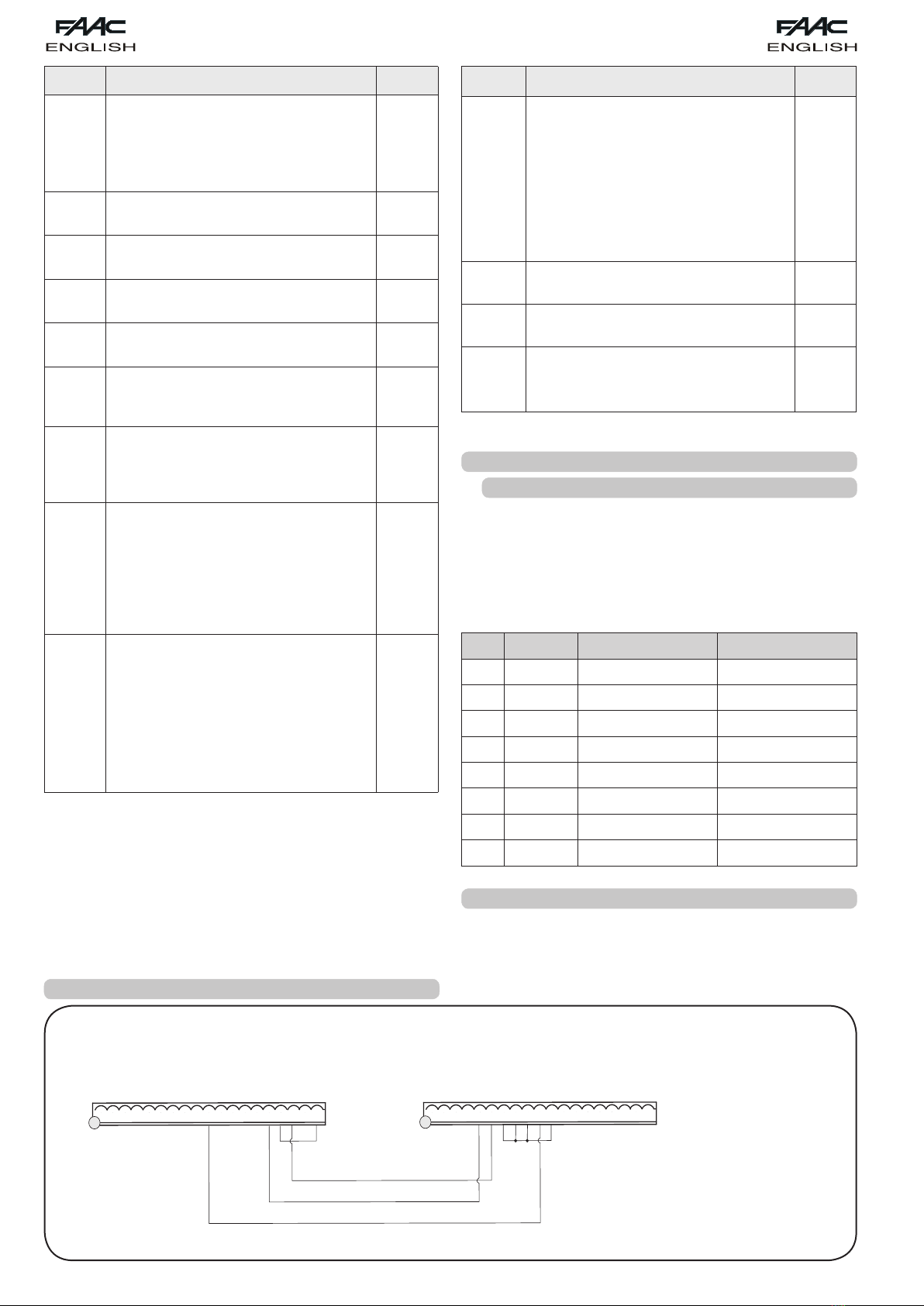
To install several total opening pulse generators,
connect the N.O. contacts in parallel (see fig. 4)
CLOSE - “Closing” Command (N.O. - terminal 6): this refers to any
pulse generator (e.g.: push-button) which, by closing a contact,
commands the barrier to close.
To install several total opening pulse generators,
connect the N.O. contacts in parallel (see fig. 4)
FSW - Closing safety-devices contact (N.C. -. terminal 7) The purpose
of the closing safety devices is to protect the barrier movement
area during closure, by reversing motion. They are never tripped
during the opening cycle. If the closing safety devices are
engaged when the automated system is in open status, they
prevent the closing movement.
To install several closing safety devices, connect the
N.C. contacts in series(fig. 3).
If closing safety devices are not connected, jumper
connect the FSW and FAIL SAFE terminals (fig. 8).
STOP - STOP contact (N.C. - terminal 8): this refers to any device
(e.g.: push-button ) which, by opening a contact, can stop the
motion of the automated system.
To install several STOP devices, connect the N.C.
contacts in series (fig. 3.).
If stop safety devices are not connected, jumper
connect the STOP and GND terminals (fig. 8).
EMERGENCY - EMERGENCY contact (N.C. - terminal 9) this refers to
any switch which, by being activated in emergency state, opens
the barrier and stops its movement until the contact is restored.
If emergency safety devices are not connected,
jumper connect the EMERGENCY and GND
terminals (fig. 8).
GND (teminals 10-11-19) - Negative contact for feeding
accessories
24 Vdc (terminals 12-13) - Positive contact for feeding
accessories
Max. load of accessories: 500 mA. To calculate
absorption values, refer to the instructions for
individual accessories.
OUT 1 - Outout 1 (terminal 14): the output can be set to one of the
functions described in 2nd level Programming (see parag. 5.2).
The default value is FAILSAFE.
OUT 2 - Output 2 (terminal 15): the output can be set to one of the
functions described in 2nd level Programming (see parag. 5.2).
The default value is beam CLOSED.
OUT 3 - Output 3 (terminal 16-17): the output can be set to one of
the functions described in 2nd level Programming (see parag.
5.2). The default value is INDICATOR LIGHT.
Connect 24 Vdc - 3 W max. indicator light , if any, to these
terminals, following the instructions in fig. 2.
To avoid endangering correct operation of the
system, do not exceed the indicated power.
OUT 4 - Output 4 (terminal 18): the output can be set to one of the
functions described in 2nd level Programming (see parag. 5.2).
The default value is Beam LIGHTED.
Connection of one safety device
Connection of no device with NC contacts.
Fig. 7
Fig. 8
4.3. J2 TERMINAL-BOARD - MOTOR - FLASHING LIGHT AND
FAN (FIG.2)
M (COM-MOT1-MOT2): Motor connection
LAMP (LAMP-COM): Flashing light output ( 230 V ~)
FAN (FAN-COM): Fan output ( 230 V ~)
4.5. J9 TERMINAL-BOARD - POWER SUPPLY (FIG.2)
PE : Earth connection
N : Power supply 230 V~ ( Neutral )
L : Power supply 230 V~ ( Line )
To ensure correct operation, the board must be
connected to the earth conductor in the system.
Install an adequate differential thermal breaker
upstream of the system.
4.4. J8 CONNECTOR - MOTOR CAPACITOR (FIG.2)
Rapid connector for connecting the motor thrust capacitor.