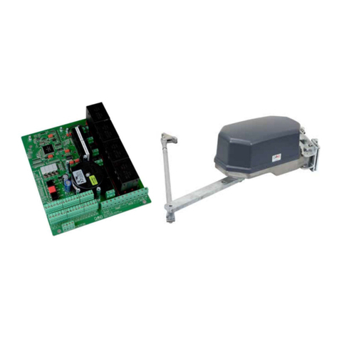
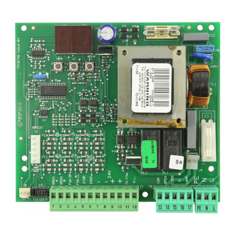
FAAC 455D220A.5 User manual

455 D455 D
Control Board
FAAC International Inc.
Headquarter & East Coast Operations
3160 Murrell Rd
Rockledge, FL 32955
Tel. 800 221 8278
www.faacusa.com
FAAC International Inc.
West Coast Operations
357 South Acacia Avenue
Fullerton, CA 92831

2
The installer is responsible for grounding the operator
system, for providing the main power breaker switch,
and for making sure that the entire gate system meets
all applicable electrical codes.
J4 J1
J3
F1
F2
PE NL
MAIN
12 45678
COMOP
M1 COMOP
M2 CL
LAMP
910111213141516171819
OPEN
AB
STP
CL OP
FSW
---
+24V
++
-TX
FSW
20 21
W.L. LOCK
J5
J2
F
22
23
24 25
FCA1
FCC1
FCA2
FCC2
–
+
STOP
OP_A
OP_B
FSWCL
FSWOP
FCC1
FCC2
FCA1
FCA2
J6
F
F1
F2
J1
J2
J3 J4
J5
J6
DL
–
+
Input Voltage 115 V~ ± 10% or
230 V~ +6% -10%
50/60 Hz
Input Power 10 W
Motor Max. Load 800 W
Accessories Max. Load 0,5 A
Electric Lock Max. Load 15 VA
Ambient Operating Temperature Range -4°F to +131°F
Protection Fuses 5A (230V version)
10A (115V Version)
800 mA (accessory)
DL STATUS AND PROGRAMMING DISPLAY
J1 LOW VOLTAGE TERMINAL BLOCK
J2 CONNECTOR FOR RADIO RECEIVER
J3 AC POWER SUPPLY TERMINAL BLOCK
J4 MOTORS AND WARNING LAMP TERMINAL BLOCK
J5 INDICATOR-LIGHT AND ELECTRIC LOCK TERMINAL BLOCK
J6 LIMIT-SWITCH TERMINAL BLOCK
F1 MOTORS AND TRANSFORMER PRIMARY WINDING
FUSE (F 5A - 230V) (F 10A - 115V)
F2 LOW VOLTAGE AND ACCESSORIES FUSE (T 800mA)
F “F” PROGRAMMING PUSH-BUTTON
– “–” PROGRAMMING PUSH-BUTTON
+ “+” PROGRAMMING PUSH-BUTTON
3. Features
Function Logics:
Semi-automatic / Automatic / Safety Devices / “Stepped” Semi-
automatic / “Stepped” Automatic / “Stepped” Safety Devices /
Semi-automatic B / Dead-man C
Opening/Closing Time:
Programmable (from 0 to 120 s)
Pause Time:
Programmable (from 0 to 4 min.)
Closing Leaf Delay:
Programmable (from 0 to 4 min.)
Opening Leaf Delay:
2 s (can be excluded)
Thrust Force:
Adjustable on 50 levels for each motor
Terminal Board Inputs:
Open / Open Free Leaf / Stop / Limit-switch / Opening Safety Devices
/ Closing Safety Devices / Power Supply + Earth.
Terminal Board Outputs:
Flashing Lamp / Motors / 24 VDC Accessories Power Supply / 24 VDC
Indicator-Light / Fail Safe / 12 VAC Electric Lock Power Supply
Programmable Functions:
Logic / Pause Time / Thrust Force / Torque at Initial Thrust / Opening and
Closing Leaf Delay / Reversing Stroke / Over-Pushing Stroke / Indicator-
Light / Pre-Flashing / Electric Lock / Fail Safe / Safety Devices Logic
/ Assistance Request / Detection Time of Obstacle or Contact Point
Learning Function:
Simple or complete work time learning, with or without Limit-switches
Terminal Block J3 - Power Supply
PE: Earth Connection / Ground
N: AC V~ power supply (Neutral)
L: AC V~ power supply (Line)
Connector J2 - Rapid Connection to RP Receivers
455D
RP 418 DS
RP 433 RC
1. General Description
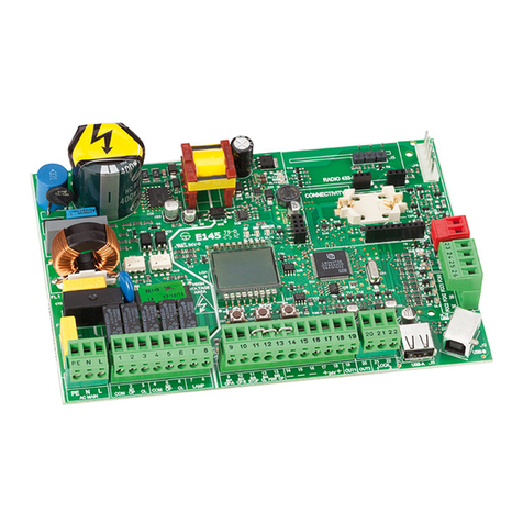
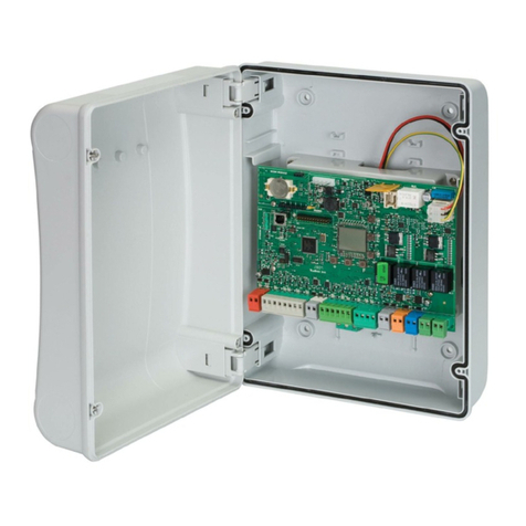
The 455 D control board is used to operate the FAAC High
Voltage swing gate operators. It has several operating logics
built in, programmable with the help of a display and push-
buttons. The board allows connection of various accessories
including monitored photocell for compliance with the
UL325 standard Ed: 7.
The 455D control board allows the connection of 1 close
and up to 2 open entrapment protection devices.
The board should be installed in an enclosure that is con-
veniently located as close as possible to the gate operator.
All electrical connections from the control board to the
operator must be made in a weatherproof junction box.
The 5 pin J2 connector allows to plug in the FAAC RP radio
receivers
455D CONTROL BOARD
2. Technical Specifications
4. Layout and Components

3
24 V DC
3W
12 V AC
FCC2
LIMIT-SWITCHES
230 VAC
or
115 VAC
60 Hz
VAC MAX.
60W
OPEN A
OPEN B
STOP
BLUE
BLUE
NO NC
Maglock
+
-
Note: Capacitors are supplied with the operator or the prewired enclosure
For connection
of the safety
devices, see the
next paragraph
Terminal Block J4 - Motors and Warning Lamp
M1: COM / OP / CL: Connection to Motor 1
Must be used for single-leaf configuration
M2: COM / OP / CL: Connection to Motor 2
Cannot be used in single-leaf configurations
LAMP: Warning lamp output ( AC V ~)
Terminal Block J1 - Accessories
OPEN A - “Total Opening” Command (N.O.):
Any pulse generator (push-button, detector, etc.) which, by
closing a contact, commands opening and/or closing of
both gate leaves. To install several full opening pulse gen-
erators, connect the N.O. contacts in parallel.
OPEN B - “Partial Opening” Command (N.O.) / Closing:
Any pulse generator (push-button, detector, etc.) which, by
closing a contact, commands opening and/or closing of
the leaf driven by motor M1. In the B and C logics, it always
commands closing of both leaves. To install several partial
opening pulse generators, connect the N.O. contacts in
parallel. See logic chart for exact operation.
STP - STOP Contact (N.C.):
Any device (e.g. a push-button) which, by opening a con-
tact, is able to stop gate movement. To install several STOP
devices, connect the N.C. contacts in series. It also can act
as an addional monitored opening safey.
Note: If STOP devices are not used, connect a jumper between
the STP terminals and -.
CL FSW - Closing Safety Contact (N.C.):
The closing safety input is used to protect the leaf move-
ment area during closing. While closing, an activation of
the the safety device connected to this input will reverse the
movement of the gate leaves. This input is inactive during
the opening cycle. To be compliant with the UL325 standard
at least one monitored safety device must be connected
to this input. See the next paragraph on how to connect
a monitored device. If this input is active when the gate is
open it will prevent the leaf closing movement.
OP FSW - Opening safety devices contact (N.C.):
The opening safety input is used to protect the leaf move-
ment area during opening. While opening, an activa-
tion of the the safety device connected to this input will
reverse the movement of the gate leaves. This input is
inactive during the closing cycle. To be compliant with the
UL325 standard if this input is used to protect an entrap-
ment zone at least one monitored safety device must be
connected to it. See the next paragraph on how to con-
nect a monitored device. If this input is active when the
gate is closed it will prevent the leaf opening movement.
– - Negative for power supply to accessories
+ - 24 VDC - Positive for power supply to accessories
Important: Accessories max. load is 500 mA. To calculate
current draw, refer to the instructions for individual
accessories.
-TX FSW - Negative Power to photocell transmitters.
This terminal is used for the photocells monitoring feature.
Compliance with the UL325 standard requires connecting
the transmitter photocell negative power to this input and
activating the FAIL SAFE function (see Advanced Program-
ming). This will allow the 455 D board to check the correct
operation of the safety photecells before each opening
or closing cycle.
Terminal Block J5 - Indicator-Light and Electric Lock
W.L. - Power supply to indicator-light
Connect a 24 VDC - 3 W max. indicator-light, if neces-
sary, between this terminal and the +24V supply. To avoid
compromising correct operation of the system, do not
exceed the indicated power.
LOCK - Power supply to electric lock
If necessary, connect a 12 Vac electric strike lock be-
tween this terminal and the +24V power supply. Or con-
nect a 12 Vac relay and a Maglock following the sche-
matic above.
Terminal Block J6 - Limit-Switches
These inputs are dedicated to the connection of opening
and closing limit switches
5. Electric Connections

4
Entrapment protection
To comply with the UL325 standard for gate operators every
entrapment zone, as defined in ASTMF2200, must be pro-
tected by two independent entrapment protection devices.
One of the devices is inherent in the FAAC operators or the
control board design, the other can be external, like a pho-
tocell or an edge sensor.
See the following picture for the photocells positioning:
Closing Safety Devices Opening Safety
Devices
Opening Safety Devices:
Are active only during the gate opening movement, and
are suitable for protecting the area between the opening
leaves and fixed obstacles (walls, etc) agains the risk of
entrapment
Closing Safety Devices:
Are active only during the gate closing movement, and are
suitable for protecting the closing area against the risk of
entrapment.
Monitored Devices:
Additionaly the UL325 standard requires that every external
entrapment protection device must be monitored for
presence and correct operation. The closing safety devices
are always monitored, see the following picture for the wiring
of a pair of photocells as closing safety devices.
NOTE: one closing safety device must always be connected
for the system to work.
1
2
5
4
3
1
2
RX CL
TX CL
910111213141516171819
OPEN
A
B
STP
CL
OP
FSW
---
+24V
++
-TX
FSW
20 21
W.L.
LOCK
-
+
-
+
1
2
5
4
3
1
2
RX OP
TX OP
-
+
-
+
-
+
-
+
+
+
1
2
5
4
3
1
2
RX CL
TX CL
910111213141516171819
OPEN
A
B
STP
CL
OP
FSW
---
+24V
++
-TX
FSW
20 21
W.L.
LOCK
-
+
-
+
-
+
+
Connection of One Pair of Monitored Closing
Photocells and One Pair of Monitored Opening
Photocells
Connection of One Pair of Monitored Closing Photocells
F+
+
ADVANCED PROGRAMMING
OPENING FAIL SAFE:
If this function is activated, it enables the
monitoring of the opening safety photocell
before he opening movement. If the test fails
the gate does not open.
= Active = Disabled
Display Function Default
Monitoring of the opening safety devices must be enabled
in the board configuration. To enable it enter in advanced
programming by pressing and holding “F” and then press
“+”, scroll to the “FS” parameter and select “Active”.
6. Connection of Safety devices
16” or less
If an additional monitored opening safety device is
needed it can be connected to the STP input. The “OP”
parameter in the board configuration must be set to active
1
2
TX OP 2
910 1 1
21
31
41
51
61
71
81
9
OPEN
A
B
STP
CL
OP
FSW
---
+24V
++
-TX
FSW
20
21
W
.L.
LOCK
-
+
5
4
3
1
2
RX OP 2
-
+
-
+
+
1
OPENING No. 2 FAIL SAFE:
When enabled the STOP input can be used for
the connection of a second monitored opening
safety device.
= Active = Disabled

5
Only one monitored photocell can be connected to the
Closing or Opening safety inputs. More than one photocell
or other device can be connected to the safety inputs, but
they will not be monitored.
Other devices connected to the safety inputs must have
normally closed contacts and wired in series with the main
monitored sensor.
See the following example of one closing safety monitored
photocell and one non monitored one.
1
2
5
4
3
1
2
RX CL1
TX CL1
1
2
5
4
3
1
2
RX CL2
TX CL2
910111213141516171819
OPEN
A
B
STP
CL
OP
FSW
---
+24V
++
-TX
FSW
20 21
W.L.
LOCK
-
+
-
+
-
+
-
+
-
+
+
-TX FSW
-
+
+
MONITORED
NON MONITORED
-
Connection of Two Pairs of Closing Photocells, One
Monitored and One Non Monitored
Opening/Closing Safety Devices:
They operate during the gate opening and closing move-
ments and are suitable to protect the opening and closing
areas against the risk of impact. Typically these photocells
work in combination with other monitored photocell pro-
tecting closing or opening entrapment zones. In that case
they can’t be monitored so they can only protect against
potential impact on vehicles.
Closing Safety Devices Opening Safety
Devices
Opening/Closing Safety Devices
1
2
5
4
3
1
2
RX CL
TX CL
1
2
5
4
3
1
2
RX OP/CL
TX OP/CL
910111213141516171819
OPEN
A
B
STP
CL
OP
FSW
---
+24V
++
-TX
FSW
20 21
W.L.
LOCK
-
+
-
+
-
+
-
+
1
2
5
4
3
1
2
RX OP
TX OP
-
+
-
+
-
+
-
+
-
+
+
+
+
-TX FSW
-TX FSW
MONITORED
MONITORED
NON MONITORED
-
Connection of One Pair of Monitored Closing
Photocells, One Pair of Monitored Opening
Photocells and One pair of Non Monitored
Opening/Closing Photocells
16” or less
1
2
5
4
3
1
2
RX CL
TX CL
1
2
5
4
3
1
2
RX OP/CL
TX OP/CL
910111213141516171819
OPEN
A
B
STP
CL
OP
FSW
---
+24V
++
-TX
FSW
20 21
W.L.
LOCK
-
+
-
+
-
+
-
+
-
+
-
+
+
-TX FSW
-
+
MONITORED
NON MONITORED
Connection of a pair of Monitored Closing
Photocells, and one pair of Non Monitored
Opening/Closing Photocell
See the following connections diagrams for example of
opening/closing safety wiring.

6
= Semi-automatic
= Automatic
= Security
= “Stepped” Semi-automatic
= “Stepped” Automatic
= “Stepped” Security
= Manned, pulsed
= Manned, constant
LEAF 1 FORCE:
Adjusts thrust of Motor 1.
= minimum force
= maximum force (*)
press F
The following table displays the sequence of functions
accessible in BASIC PROGRAMMING:
BASIC PROGRAMMING
PAUSE TIME:
This has effect only when automatic logic is selected.
Adjustable from to secs. in one-second
increments.
Subsequently, display changes to minutes and tenths
of seconds (separated by a decimal point), time
is adjusted in 10-second increments, up to
minutes max. Thus, if the unit displays , Pause
Time is 2 mins. and 50 secs.
Exit from programming and return to inputs status
monitoring.
8. Programming
To program the 455D Control Board, you have to access
“PROGRAMMING” mode. Programming is split into two parts:
BASIC and ADVANCED.
LEAF 2 FORCE:
Adjusts thrust of Motor 2.
= minimum force
= maximum force (*)
LEAF 1 CLOSING DELAY:
Delays closing start of leaf 1 with respect to
leaf 2. Adjustable from to minutes (see
Pause Time).
TIME LEARNING (see Section 10):
Enables the selection between “simple”
learning and “complete” (manual choice of
deceleration and stop points) learning.
+≈1 s.
Simple Learning:
> 3 s.
Complete Learning:
OPERATING LOGICS (see tab. 3/a - h):
(*) For hydraulic operators, set force to the maximum
level.
Basic Programming:
To access BASIC PROGRAMMING, press key F:
• Press and hold F, the unit will display the name of the first
function / parameter.
• When you release the key, the unit will display the param-
eter’s current value.
• Value can be modified with keys +and - .
• Press and hold Fagain, the unit will display the name of
the next function / parameter.
• When you reach the last function, press Fto exit the pro-
gram, the display resumes monitoring input status.
• IMPORTANT: Make sure to exit programming mode other-
wise the changes will not be saved.
Display Function Default
+
7. Operating Logics
This is a brief description of the main operating logics of the
system. For a complete description please refer to Table 3
• E (semi-automatic): This mode requires a command to
open and a command to close. A second command
during opening stops the gate. A second command
during closing reopens the gate.
• A (automatic): The gate opens on command and
automatically closes after the pause time. A second
command while opening is ignored; a second com-
mand during the pause phase interrupts the pause
time; a second command during closing reopens the
gate. A maintained open command will hold the gate
open.
• S (security): The security mode is like A logic except
that a second command during opening immediately
closes the gate. A maintained open command will not
hold the gate open.
• EP (semi-automatic, step by step): This mode requires
a command to open and a command to close. A
second command during opening or closing causes
the gate to stop. A third command then reverses the
previous motion of the gate.
• B (manned, pulsed): This mode is designed for guard
station use and requires a three button switch (pulsed)
to open, close, and stop the gate.
• C (manned and constant): This mode requires con-
stant pressure switches. One to open and one to close.
No pressure on a switch stops the gate.

7
F+
+
Advanced Programming:
To access ADVANCED PROGRAMMING, press and hold key F
and then press key +:
• Release key +, the unit displays the name of the first
function.
• Release key F, modify the value of the function with keys
+ and -.
• Press and hold key F, the unit displays the name of the
next function, and if you release it, the value that can be
modified with keys + and -.
• When you reach the last function, press F to exit the pro-
gram, the unit resumes monitoring input status.
The following table shows the sequence of functions
accessible in ADVANCED PROGRAMMING:
ADVANCED PROGRAMMING
MAXIMUM TORQUE AT INITIAL THRUST:
The motors operate at maximum torque
(ignoring the torque setting) at start of
movement. Useful for heavy leaves.
= Active = Disabled
LAST STROKE AT CLOSING:
The motors are activated at full speed for 1
second to facilitate locking of the electric lock.
= Active =Disabled
REVERSING STROKE:
Before opening, while the gate is closed,
the motors thrust to close for 2 seconds thus
facilitating release of the electric lock.
= Active = Disabled
LEAF 2 OPENING DELAY (2 s):
Enables delayed start (at opening) of leaf 2,
avoiding interference between leaves.
= Active = Disabled
OPENING FAIL SAFE:
If this function is activated, it enables the
monitoring of the opening safety photocell
before the opening movement. If the test fails
the gate does not open.
= Active = Disabled
PRE-FLASHING (5 s):
Activates the flashing lamp for 5 seconds before
start of movement.
= Active = Disabled
ELECTRIC LOCK ON LEAF 2:
For using the electric lock on leaf 2 instead
of on leaf 1.
= Active = Disabled
INDICATOR-LIGHT:
: the output functions as a standard indicator-
light (ON at opening and pause, flashing at
closing, and OFF when gate is closed).
: the output is ON when the gate is open or
in pause. OFF in all other conditions.
the output is ON when the gate is closed.
OFF in all other conditions.
All other values correspond to the extra time
compared to normal work time (opening or
closing) when the output can be used - via a
relay - to power a courtesy light. Time can be
adjusted from to sec. in 1 sec. steps,
and from to min. in 10 sec. steps.
CLOSING PHOTOCELLS REVERSE AT RELEASE:
Enable this function if you want the closing
photocells to stop movement and reverse at
release. Default setting is immediate reverse.
= Active = Disabled
ASSISTANCE REQUEST (combined with next
function):
If activated, at the end of countdown (settable
with the next function i.e. “Cycle programming”)
it affects 8 s of pre-flashing at every Open
pulse (job request). Can be useful for setting
scheduled maintenance jobs.
= Active = Disabled
CYCLE PROGRAMMING:
For setting countdown of system operation
cycles. Settable (in thousands) from to
thousand cycles. The displayed value is updated
as cycles proceed.
This function can be used to check use of the
board or to exploit the “Assistance request”.
OPENING No. 2 FAIL SAFE:
When enabled the STOP input can be used
for the connection of a second monitored
opening safety device
= Active = Disabled
Exit from programming and return to inputs
status monitoring.
NOTE: Parameter modifications take effect immediately.
Exit out of programming to save changes. If the equipment
is powered down before returning to normal status monitor-
ing, any unsaved modifications will be lost.
To restore programming defaults, press and hold the
three buttons +, -, F simultaneously for 5 seconds.
EXTRA WORK TIME:
If reversing occurs, and if the leaf does not
reach its end contact point, you can activate
this function to increase work time.
= Active = Disabled
Display Function Default

8
9. Start-up
LED Indicators:
The board has a two-digit display. When not in
“PROGRAMMING” mode, this display is used to indicate
the status of inputs. The figure below shows how the LED
segments are mapped to the corresponding the inputs.
The table below shows the status of the LEDs in relation to
the status of the inputs.
Note the following: LED ON = closed contact
LED OFF = open contact
Operation of the Status Signaling LEDs
The status of the LEDs while the gate is closed at rest are shown
in bold.
Rotation direction and force check:
1. Program the functions of the 455 D control board ac-
cording to need, as previously shown.
2. Turn power off to the control board.
3. Release the operators and manually move the gate
to the mid-point of the opening angle.
4. Re-lock the operators.
5. Restore power.
6. Send an opening command on the OPEN A input and
verify that the gate leaves start moving towards the
open position
Note: If the first OPEN A pulse starts a closing movement,
turn power off and reverse the phases of the electric
motor (red and black wires) on the 455 D control board.
7.
Check force setting of the motors, modify if necessary.
Note: For hydraulic operators, like the 400, force should be
programmed to maximum level (50)
8. Stop leaf movement with a pulse on the STOP input or
turning off power.
9. Release the operators, close the leaves and re-lock
the operators.
Opening/closing time is established by a time learning pro-
cedure which can be accomplished in “simple” or “com-
plete” modes. The simple mode doesn’t allow a slow down
phase in the operator, while the complete mode does.
The slow down can be useful to reduce the mechanical
stress on the gate, but it can create problems in high wind
conditions.
LEDs ON OFF
OP_A
Command activated Command inactive
OP_B
Command activated Command inactive
STOP
Command inactive Command activated
FSWCL
Safety devices clear Safety devices triggered
FSWOP
Safety devices clear Safety devices triggered
FCA1 (if used)
Limit switch free Limit switch triggered
FCC1 (if used)
Limit switch free Limit switch triggered
FCC2 (if used)
Limit switch free Limit switch triggered
FCA2 (if used)
Limit switch free Limit switch triggered
This is the normal status of the display with all the safety
inputs clear and no activation signal present

9
WARNING:During the learning procedure, safety
devices are disabled! Avoid crossing the leaf
movement area when this operation is carried out.
Make sure travel limit mechanical stops are present.
10. Learning Operating Times
- SIMPLE LEARNING (Without Slow Down):
Check that the leaves are closed. Enter “BASIC
PROGRAMMING,” select the TIME LEARNING function and
then press the +push-button for 1 second. The display
begins flashing and the leaves begin to open.
As soon as the leaves reach the opening contact point,
provide an OPEN A pulse (with the key operated push-button
or with the radio control) to stop the movement. The leaves
stop and the display stops flashing.
Press push-button Fto exit and save the programming. The
procedure is complete and the gate is ready to operate.
- COMPLETE LEARNING (With Slow Down):
Check that the leaves are closed. Enter “BASIC
PROGRAMMING,” select the TIME LEARNING function and
then press the +push-button for more than 3 seconds.
The display begins flashing and leaf 1 begins to open. The
following functions can be performed by sending OPEN A
pulses (by key push-button or radio control).
A total of 8 OPEN A commands required:
1. Slow down at opening of leaf 1
2. Leaf 1 stops at opening and leaf 2 begins its opening
movement
3. Slow down at opening of leaf 2
4. Leaf 2 stops at opening and immediately begins its
closing movement
5. Slow down at closing of leaf 2
6. Leaf 2 stops at closing and leaf 1 begins its closing
movement
7. Slow down at closing of leaf 1
8. Leaf 1 stops at closing
When the display stops flashing, press push-button Fto exit
and save the programming. The procedure is complete
and the gate is ready to operate.
Notes:
• If you wish to eliminate deceleration in certain stages,
wait for the leaf to reach its stop-limit and supply 2
consecutive Open pulses (by 1 second).
• If only one leaf is present, the entire sequence must
nevertheless be completed. When the leaf has finished
opening, supply 5 Open pulses until the leaf begins to
close, and then resume normal operation.
11. Final Tests
Once programming is complete and the proper operating
times are stored in the board’s memory perform a
complete test the system. Verify that the operator(s)
run properly and, most importantly, check that force is
adequately adjusted and that safety devices are operating
correctly.
After simple or complete learning the board will add 3 sec.
to the programmed time so the operators will run against
the stops.
Monitored safety test:
IMPORTANT: To make sure that the safety photocells
protecting entrapment zones are monitored properly install
a temporary jumper on the N.C. output of the photocell
and give an OPEN A command. The gate must not move,
otherwise check the wiring of the photcells and make sure
that FAIl SAFE is enabled in Advanced Programming

10
Tab. 3/a
Tab. 3/b
Tab. 3/c
Tab. 3/d
"A"cigoL SESLUP
SUTATSETAG A
-NEPO B
-NEPO P
OTS S
ECIVEDYTEFASGNINEPO S
ECIVEDYTEFASGNISOLC E
CIVEDYTEFASLC/PO
DESOLC
sesolcdnafaelehtsnepO
)1(emitesuapretfati
sesolcdnafaelelgnissnepO
)1(emitesuapretfa
tceffeoN
)delbasidNEPO( tceffeoN tceffeoN
)delbasidNEPO(
ESUAPnoNEPO
)3()1(emitesuapsdaoleR
spotS
noitarepo
tceffeoN
)delbasidANEPO.gnpo.trapnofi( )3()1(emitesuapsdaoleR )1(emitesuapsdaoleR
)delbasidNEPO(
GNISOLC
)1(yletaidemmifaelehtsne
po-eR tceffeoN
)NEPOsevas( .2.5hpargarapees otsesrever,esaelerno,dnaskcoL
nepo
GNINEPO
)3()1(tceffeoN esolcotsesreveR t
ceffeoN seunitnoc,esaelerno,dnaskcoL
gninepo
DEKCOL
)3(faelehtsesolC tceffeoN
)delbasidNEPO( tceffeoN tceffeoN
)delbasidNEPO(
"S"cigoL SESLUP
SUTATSETAG A
-NEPO B
-NEPO P
OTS S
ECIVEDYTEFASGNINEPO S
ECIVEDYTEFASGNISOLC E
CIVEDYTEFASLC/PO
DESOLC
sesolcdnafaelehtsnepO
emitesuapretfati
sesolcdnafaelelgnissnepO
emitesuapretfa
tceffeoN
)delbasidNEPO( tceffeoN
tceffeoN
)delbasidNEPO(
ESUAPnoNEPO
)3(yletaidemmifaelehtsesolc-eR
spotS
noitarepo
tceffeoN
)delbasidANEPO.gnpo.trapnofi(
NEPO("5retfasesolc,esaelernO
)3()delbasid
"5retfasesolc,esaelernO
)delbasidNEPO(
GNISOLC
yletaidemmifaelehtsnepo-eR tceffeoN
)NEPOsevas( .2.5hpargarapees otsesrever,esaelerno,dnaskcoL
nepo
GNINEPO
)3(yletaidemmifaelehtsesolc-eR esolcotsesreveR tceffeoN
)NEPOsevas(
seunitnoc,esaelerno,dnaskcoL
gninepo
DEKCOL
)3(faelehtsesolC tceffeoN
)delbasidNEPO( tceffeoN tceffeoN
)delbasidNEPO
"E"cigoL SESLUP
SUTATSETAG A
-NEPO B
-NEPO P
OTS S
ECIVEDYTEFASGNINEPO S
ECIVEDYTEFASGNISOLC E
CIVEDYTEFASLC/PO
DESOLC
faelehtsnepO f
aelelgnissnepO tceffeoN
)delbasidNEPO( tceffeoN tceffeoN
)delbasidNEPO(
NEPO
)3(yletaidemmifaelehtsesolc-eR
spotS
noitarepo
tceffeoN
)delbasidANEPO.gnpo.trapnofi(
)3(tceffeoN
)delbasidNEPO(
tceffeoN
)delbasidNEPO(
GNISOLC
yletaidemmifaelehtsnepo-eR tceffeoN
)NEPOsevas( .2.5hpargarapees otsesrever,esaelerno,dnas
kcoL
nepo
GNINEPO
)3(noitarepospotS esolcotsesreveR t
ceffeoN seunitnoc,esaelerno,dnaskcoL
gninepo
DEKCOL
,degagnesecivedytefaSgnisolChtiw(faelehtsesolC
)3()eslupdn2ehttasnepo
tceffeoN
)delbasidNEPO( tceffeoN tceffeoN
)delbasidNEPO(
PULSES
GATE STATUS
OPEN-A
OPEN-B
STOP
OPENING SAFETY DEVICES
CLOSING SAFETY DEVICES
OP/CL SAFETY DEVICE
CLOSED
Opens the leaf Opens leaf for the partial
opening time
No effect
(OPEN disabled) No effect No effect (OPEN disabled)
OPEN
Re-closes the leaf immediately (3)
Stops
operation
No effect (if on part.opng. OPEN A
disabled) No effect (OPEN disabled) (3) No effect (OPEN disabled)
CLOSING
Stops operation No effect (saves OPEN) see paragraph 5.2. Locks and, on release, reverses to
open
OPENING
Stops operation (3) see paragraph 5.2. No effect Locks and, on release, continues
opening
LOCKED
Restarts movement in reverse direction (3)
(always closes after a Stop)
No effect
(OPEN disabled)
No effect
(if it must open, it disables OPEN)
No effect
(if it must close, it disables OPEN) No effect (OPEN disabled)
Logic "EP"
(1) If maintained, it prolongs the pause until disabled by the command (timer function)
(3) During the partial opening cycle, an OPENApulse causes total opening.
(2) Ifanew pulse occurs within2seconds after reversing, it immediately stops operation.
NB.: Effects on other active pulse inputs in brackets.
12. Operating Modes Detailed Description

11
Tab. 3/e
Tab. 3/f
Tab. 3/g
Tab. 3/h
"C"cigoL N
WODDLEHSYAWLASLORTNOC SESLUP
SUTATSETAG )
gninepo(A-NEPO )
gnisolc(B-NEPO P
OTS S
ECIVEDYTEFASGNINEPO S
ECIVEDYTEFASGNISOLC E
CIVEDYTEFASLC/PO
DESOLC
faelehtsnepO tceffeoN
)delbasidA-NEPO(
tceffeoN
)delbasidANEPO( tceffeoN tceffeoN
)delbasidANEPO(
NEPO
tceffeoN
)delbasidB-NEPO( faelehtsesolC tceffeoN
)delbasidB/A-NEPO(
tceffeoN
)delbasidANEPO(
tceffeoN
)delbasidBNEPO(
tceffeoN
)delbasidBNEPO(
GNISOLC
noitarepospotS /
noitarepospotS
tce
ffeoN noitarepospotS
)delbasidB-NEPO( noitarepospotS
)delbasidB/A-NEPO(
GNINEPO
/ n
oitarepospotS noitarepospotS
)delbasidA-NEPO( tceffeoN
"B"cigoL SESLUP
SUTATSETAG )
gninepo(A-NEPO )
gnisolc(B-NEPO P
OTS S
ECIVEDYTEFASGNINEPO S
ECIVEDYTEFASGNISOLC E
CIVEDYTEFASLC/PO
DESOLC
faelehtsnepO t
ceffeoN tceffeoN
)delbasidANEPO( tceffeoN tceffeoN
)delbasidANEPO(
NEPO
tceffeoN f
aelehtsesolC NEPO(tceffeoN
)delbasidB tceffeoN tceffeoN
)delbasidBNEPO(
tceffeoN
)delbasidBNEPO(
GNISOLC
nepootsesreveR t
ceffeoN spotS
noitarepo
tceffeoN
)ANEPOsevas(
noitarepospotS
)delbasidB-NEPO( noitarepospotS
)delb
asidB/A-NEPO(
GNINEPO
tceffeoN t
ceffeoN noitarepospotS
)delbasidA-NEPO( tceffeoN
DEKCOL
faelehtsnepO f
aelehtsesolC tceffeoN
)delbasidB/ANEPO(
tceffeoN
)delbasidA-NEPO(
tceffeoN
)delbasidBNEPO(
tceffeoN
)delbasidB/ANEPO(
(1) If maintained, it prolongs the pause until disabled by the command (timer function)
(3) During the partial opening cycle, an OPENApulse causes total opening.
(2) Ifanew pulse occurs within2seconds after reversing, it immediately stops operation.
NB.: Effects on other active pulse inputs in brackets.
"PA"cigoL SESLUP
SUTATSETAG A
-NEPO B
-NEPO P
OTS S
ECIVEDYTEFASGNINEPO S
ECIVEDYTEFASGNISOLC E
CIVEDYTEFASLC/PO
DESOLC
sesolcdnafaelehtsnepO
emitesuapretfati
sesolcdnafaelelgnissnepO
emitesuapretfa
tceffeoN
)delbasidNEPO( tceffeoN tceffeoN
)delbasidNEPO(
ESUAPnoNEPO
)3(noitarepospotS
spotS
noitarepo
tceffeoN
)delbasidANEPO.gnpo.trapnofi(
)3(emitesuapsdaoleR
)delbasidNEPO(
emitesuapsdaoleR
)delbasidNEPO(
GNISOLC
yletaidemmifaelehtsnepo-eR tceffeoN
)NEPOsevas( .2.5hpargarapees otsesrever,esaelerno,dnaskcoL
nepo
GNINEPO
)3(noitarepospotS esolcotsesreveR t
ceffeoN seunitnoc,esaelerno,dnaskcoL
gninepo
DEKCOL
,degagnesecivedytefaSgnisolChtiw(faelehtsesolC
)3()eslupdn2ehttasnepo
tceffeoN
)delbasidNEPO( tceffeoN tceffeoN
)delbasidNEPO(
"PS"cigoL SESLUP
SUTATSETAG A
-NEPO B
-NEPO P
OTS S
ECIVEDYTEFASGNINEPO S
ECIVEDYTEFASGNISOLC E
CIVEDYTEFASLC/PO
DESOLC
sesolcdnafaelehtsnepO
emitesuapretfati
sesolcdnafaelelgnissnepO
emitesuapretfa
tceffeoN
)delbasidNEPO( tceffeoN tceffeoN
)delbasidNEPO(
ESUAPnoNEPO
)3(noitarepospotS
spotS
noitarepo
tceffeoN
)delbasidANEPO.gnpo.trapnofi(
NEPO("5retfasesolc,esaelernO
)3()delbasid
"5retfasesolc,esaelernO
)delbasidNEPO(
GNISOLC
yletaidemmif
aelehtsnepo-eR tceffeoN
)NEPOsevas( .2.5hpargarapees otsesrever,esaelerno,dnaskcoL
nepo
GNINEPO
)3(noitarepospotS esolcotsesreveR tceffeoN
)NEPOsevas(
seunitnoc,esaelerno,dnaskcoL
gninepo
DEKCOL
)3(faelehtsesolC tceffeoN
)delbasidNEPO( tceffeoN tceffeoN
)delbasidNEPO

12
The 455D board can be easily installed in a prewired enclosure supplied by FAAC that integrates a number of functions: Power
ON-OFF switch and accessory power outlet, loop detector sockets prewired to the board, large terminal strips to easily connect
activations, accessories and safeties.
+OP -CL
+24 V
FSW
NC -B -
STOP
A+TX
FSW
9 10 11 12 13 14 15 16 17 18 19
J1
RADIO
F2
F1
M
M
K
W. L. LOCK
22 23 24 25
LAMP
COM OP CL
MOTOR 1 MOTOR 2
CL
COM OP
1 2 3 4 5 6 7 8 20 21
FCA1
FCA2
FCC2
FCC1
F
-
+
J2
J6J4 J5
J3
N L
MAIN
+OP -CL
+24 V
FSW
-B -
STOP
A+TX
FSW
9 10 11 12 13 14 15 16 17 18 19
J1
PHOTO
OP
OPEN
DEVICES
PHOTO
CL
24VDC
RX PHOTO
24VDC
TX PHOTO
LOCK
REMOVE JUMPER
IF DETECTOR IS USED
+ - + -
SHADOW
INPUT
FREE EXIT DETECTOR BASE
REVERSE DETECTOR BASE
7
8
FREE EXIT
LOOP
7
8
SAFETY
LOOP
MASTER OPERATOR SLAVE OPERATOR
Line Voltage
MOTOR
ON
24 VDC
- + +
+ -
24 VDC
MAG LOCK
WHITE
BLACK
RED
GREEN
WHITE
BLACK
RED
GREEN
BLACK
RED (230V)
GREEN
WHITE
115V LINE
115V LINE
GROUND
NEUTRAL
115 V
230 V
TEST
BUTTON
REMOVE JUMPER
IF SHADOW KIT
IS USED
13. Prewired Enclosure

13
AC Power Wiring Guidelines
1. Check local wiring codes in all cases and follow all
local building codes. Wiring and hookup should be
performed by qualified electricians/installers only.
2. AC power should be supplied from a circuit breaker
panel and must have its own dedicated circuit breaker.
This supply must include a green ground conductor.
3. Properly ground the gate operator to minimize or
prevent damage from power surges and/or lightning.
Use a grounding rod if necessary. A surge suppressor is
recommended for additional protection.
BLACK
RED (230V)
GREEN
WHITE
115V LINE
115V LINE
GROUND
NEUTRAL
115 V
230 V
TX
TX
RX
RX
PHOTO
OP
OPEN
DEVICES
PHOTO
CL
24VDC
RX PHOTO
24VDC
TX PHOTO
+ - + -
SHADOW
INPUT
TEST
BUTTON
24VDC
RX PHOTO
24VDC
RX PHOTO
a b a b
PHOTO
OP
a
b
a
b
OPEN SAFETY MONITORED
CLOSE SAFETY MONITORED
-
+
-
+
PHOTO
CL
Monitored safety connections
The prewired enclosure comes with dedicated terminal
blocks for the connection of safety photocells that can be
monitored by the control board for presence and correct
operation. One closing and one opening photocells can be
connected to the dedicated terminals.
1. Connect the trasnsmitter photocell(s) to the 24VDC TX
PHOTO terminals as shown on the drawing
2. Connect the receiver photocell(s) 24V power to the
24VDC RX PHOTO terminals as shown on the drawing
3. For applications that need only closing safeties connect
the N.C. outputs of the photocell to the PHOTO CL termi-
nals and connect a jumper to the PHOTO OP terminals
4. For applications that need closing and opening safeties
connect the N.C. outputs of the photocells to the PHOTO
CL and PHOTO OP terminals. Program the FS paramenter
in advance programming to Y
IMPORTANT: The operator requires the connection of the
closing safety photocell to work.
TXRX
PHOTO
OP
OPEN
DEVICES
PHOTO
CL
24VDC
RX PHOTO
24VDC
TX PHOTO
+ - + -
SHADOW
INPUT
TEST
BUTTON
24VDC
RX PHOTO
a b a b
a
b
CLOSE SAFETY MONITORED
-
+
PHOTO
CL

14
LOCK
24 VDC
- + +
+ -
24 VDC
MAG LOCK
24V AC
MAGLOCK KIT OPTION
Maglock connection
The prewired enclosure comes with dedicated terminal
blocks for the connection of a relay to drive a Maglock.
The Maglock kit can be ordered separately as an accessory.
Refer to this schematic for the connections.
If using non-FAAC relay make sure the minimum switch volt-
age is less than 12Vac
SHADOW
INPUT
Line Voltage
MOTOR
ON
24 VDC
- +
SHADOW
LOOP
120V or 230 AC
SHADOW KIT OPTION
8
7
10
1
25
Shadow Loop kit option
The prewired enclosure comes with dedicated terminal
blocks for the connection of a relay and a loop detec-
tor socket to implement the shadow loop functionality. The
Shadow loop kit can be ordered separately as an accessory.
Refer to this schematic for the connections.

15
FAAC International, Inc. (“Seller”) warrants the first Purchaser
of the product to be free from defects in material and work-
manship for a specific period as defined by the Warranty
disclosure on the website www.faacusa.com. The Warranty
Period commences from the date of invoice.
Control Boards, Accessories or Spare Parts factory installed
or sold with any of the products above carry the same
warranty period as the product they are sold with, excluding
batteries that carry a maximum 2 year warranty.
Products repaired under warranty carry the remainder of
the original warranty period. For products repaired outside
of warranty, the Seller warrants that all parts used for the re-
pair will be free from defects in materials and workmanship
for a period of ninety (90) days.
Defective products must be returned to Seller, freight
prepaid by Purchaser, within the warranty period. A Return
Material Authorization Number (RMA) must be obtained
before product is returned. Items returned will be repaired
or replaced, at Seller’s option, upon an examination which
discloses to the satisfaction of the Seller that the item is
defective. The Seller will return the warranted item freight
prepaid.
This limited Warranty covers the product under the normal
use and service for which it was intended, provided it has
been properly installed and operated. Seller’s obligations
under this warranty shall be limited to the repair or ex-
change of any part. This warranty shall not apply to prod-
ucts or parts thereof which have been repaired or altered,
without Seller’s written consent, outside of Sellers’s workshop
or altered in any way so as, in the judgment of Seller, to
affect adversely the stability or reliability of the product(s)
or has been subject of misuse, negligence, or accident, or
has not been operated in accordance with the product’s
instructions or has been operated under conditions more
severe than, or otherwise exceeding, those set forth in the
specifications for such product(s).
When the warranty service involves the exchange of an
operator or part, the item the Seller replaces becomes its
property and the replacement becomes Purchaser’s prop-
erty. The Purchaser represents that all removed items are
genuine and unaltered. The replacement may not be new
but will be in good working order and at least functionally
equivalent to the item replaced. The replacement assumes
the warranty service status of the replaced item.
The products are not warranted to meet the specific re-
quirements, if any, of safety codes of any particular state,
municipality, or other jurisdiction, and the Seller doesn’t
assume any risk or liability whatsoever resulting from the use
thereof, whether used singly or in combination with other
machines or apparatus.
The Seller does not assume nor authorizes any person to as-
sume for them any other liability in connection with the sale
or use of the products of beyond that extended herein.
The warranty hereinabove set forth shall not be deemed
to cover maintenance parts, including, but not limited to
hydraulic oil, motor brushes, or the like. No agreement to
replace or repair shall constitute an admission by the Seller
of any legal responsibility to effect such replacement to
make such repair, or otherwise.
All products sold by the Seller are subject to design and/or
appearance modifications, which are production standards
at the time of shipment. The Seller may, but shall not be
required to, modify or update products shipped prior to a
current production standard.
THIS WARRANTY IS EXPRESSLY IN LIEU OF ALL OTHER WARRAN-
TIES EXPRESSED OR IMPLIED INCLUDING THE WARRANTIES
OF MERCHANTABILITY AND FITNESS FOR USE. THIS WARRANTY
SHALL NOT APPLY TO PRODUCTS OR ANY PART THEREOF WHICH
HAVE BEEN SUBJECT TO ACCIDENT, NEGLIGENCE, ALTERATION,
ABUSE, OR MISUSE OR IF DAMAGE WAS DUE TO IMPROPER
INSTALLATION OR USE OF IMPROPER POWER SOURCE, OR IF
DAMAGE WAS CAUSED BY FIRE, FLOOD, LIGHTNING, ELECTRI-
CAL POWER SURGE, EXPLOSION, WIND STORM, HAIL, AIRCRAFT
OR VEHICLES, VANDALISM, RIOT OR CIVIL COMMOTION, OR
ACTS OF GOD.
The Seller shall not be liable for any loss or damage what-
soever resulting, directly or indirectly, from the use or loss
of use of the product(s). Without limiting the foregoing, this
exclusion from liability embraces a Purchaser’s expenses for
downtime or for making up downtime, lost profit, damages
for which the Purchaser may be liable to other persons,
damage to property, and injury to or death of any persons.
This limited warranty extends only to wholesale custom-
ers who buy directly through the Seller’s normal distribution
channels. The Seller does not warrant its products to end
consumers. Consumers must inquire from their selling dealer
as to the nature and extent of that dealer’s warranty, if any.
THE LIMITED WARRANTY OFFERED HEREIN IS THE SOLE AND
EXCLUSIVE REMEDY AVAILABLE TO THE PURCHASER. CORREC-
TION OF DEFECTS, IN THE MANNER AND FOR THE PERIOD OF
TIME DESCRIBED HEREIN, SHALL CONSTITUTE THE COMPLETE
FULFILLMENT OF ALL LIABILITIES OF SELLER TO THE PURCHASER
WITH RESPECT TO THE COVERED PRODUCT, AND SHALL CON-
STITUTE FULL SATISFACTION OF ALL CLAIMS, WHETHER BASED
ON CONTRACT, NEGLIGENCE, STRICT LIABILITY OR OTHERWISE.
IN NO EVENT SHALL SELLER BE LIABLE FOR ANY LOSS OF PROF-
ITS OR ANY INDIRECT, CONSEQUENTIAL, INCIDENTAL, SPECIAL
OR PUNITIVE DAMAGES ARISING OUT OF SELLER‘S BREACH OF
THIS LIMITED WARRANTY, OR ARISING OUT OF THE CUSTOMER’S
INABILITY TO USE THE COVERED PRODUCT, EVEN IF SELLER HAS
BEEN ADVISED OF THE POSSIBILITY OF SUCH DAMAGES.
Some states do not allow the exclusion or limitation of inci-
dental or consequential damages, so the above limitation
may not apply to a particular Purchaser. This Limited War-
ranty gives the Purchaser specific legal rights. The Purchaser
may also have other rights, which vary from state to state.
LIMITED WARRANTY

© 2021, FAAC International, Inc. - All Rights Reserved
Published in Jan. 2021
455D - 532218 - Rev.B - US
This manual suits for next models
2
Other FAAC Controllers manuals
Popular Controllers manuals by other brands

Reflex
Reflex Reflexomat Compact RC Series operating manual

Carrier
Carrier MPC Open XP Series Installation and startup guide

CARLO GAVAZZI
CARLO GAVAZZI RSBS Series manual

Franklin Electric
Franklin Electric SubDrive75 installation manual

Razer
Razer SERVAL manual

Leroy-Somer
Leroy-Somer R452 Installation and Maintenance