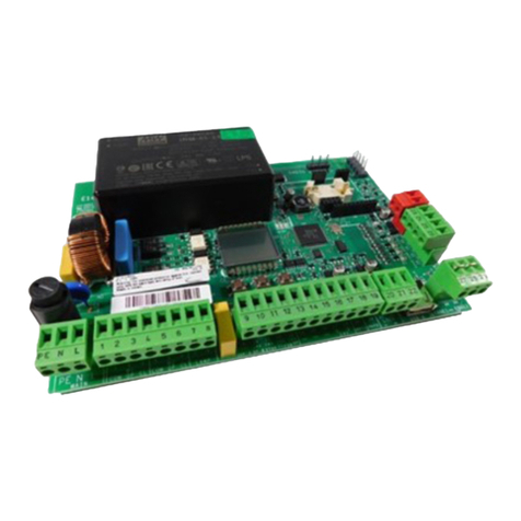
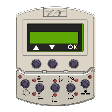
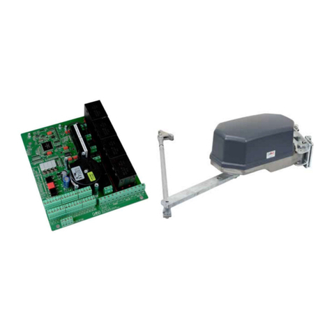
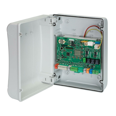
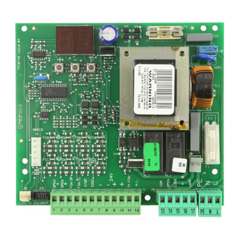
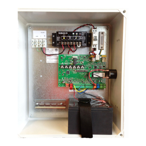
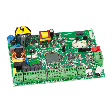
FAAC E024S User manual

E024S

7326421 - Rev. A
E024S
ATTENZIONE
PRIMA DI EFFETTUARE IL SETUP SELEZIONARE
CON I DIP SWITCH DS1(DS3-DS4) L’OPERATORE
COLLEGATO ALL’APPARECCHIATURA E024S.
PER TUTTI GLI ALTRI SETTAGGI FARE RIFERIMENTO
AL MANUALE ISTRUZIONI E024S.
ATTENTION
BEFORE PERFORMING THE SETUP, SELECT
THE OPERATOR CONNECTED TO THE E024S
EQUIPMENT WITH THE DS1(DS3-DS4) DIP
SWITCHES.
FOR ALL OTHER SETTINGS, REFER TO THE E024S
INSTRUCTION MANUAL.
ATTENTION
AVANT D'EFFECTUER LE SETUP, SÉLECTIONNER
L'OPÉRATEUR CONNECTÉ À L'ÉQUIPEMENT E024S
À L'AIDE DES DIP SWITCH DS1(DS3-DS4).
POUR TOUTES LES AUTRES OPÉRATIONS DE SETUP,
REPORTEZ-VOUS AU MANUEL D'INSTRUCTIONS
E024S.
ACHTUNG
VOR DER DURCHFÜHRUNG EINES SETUPS MUSS
MIT DEN DIP-SWITCHES DS1(DS3-DS4) DER AN
DIE ANLAGE E024S ANGESCHLOSSENE ANTRIEB
ANGEWÄHLT WERDEN.
ANLEITUNGEN ÜBER ALLE ANDEREN
EINSTELLUNGEN SIND DER BETRIEBSANLEITUNG
E024S ZU ENTNEHMEN.
ATENCIÓN
ANTES DE EFECTUAR EL SETUP SELECCIONAR
CON LOS DIP SWITCHES DS1 (DS3-DS4) EL
OPERADOR CONECTADO AL EQUIPO E024S.
PARA TODAS LAS OTRAS CONFIGURACIONES
TOMAR COMO REFERENCIA EL MANUAL DE
INSTRUCCIONES E024S.
LET OP
ALVORENS DE SETUP UIT TE VOEREN, MOET
MET DE DIPSCHAKELAARS (DS3-DS4) DE
AANDRIJVING WORDEN GESELECTEERD DIE
OP HET APPARAAT E024S IS AANGESLOTEN.
RAADPLEEG VOOR ALLE ANDERE INSTELLINGEN
DE INSTRUCTIEHANDLEIDING E024S.
DS4 DS3 DS2 DS1 Description
OFF OFF 391
ON OFF S418
OFF ON 412-413-415-390-770
ON ON HYDRAULIC MOTOR
S450H/S700H/S800H/S800H ENC
OFF OFF LOW FORCE
ON OFF MEDIUM - LOW FORCE
OFF ON MEDIUM - HIGH FORCE
ON ON HIGH FORCE

E024S 3 732642 - Rev. F
WARNINGS
• Important!Forthesafetyofpeople,itisimportantthatalltheinstructionsbecarefullyobserved.
• Incorrectinstallationorincorrectuseoftheproductcouldcauseseriousharmtopeople.
• Carefullyreadtheinstructionsbeforebeginningtoinstalltheproductandkeepthemforfuturereference.
• Thesymbol indicatesnotesthatareimportantforthesafetyofpersonsandforthegoodcondition
oftheautomatedsystem.
• Thesymbol drawsyourattentiontothenotesonthecharacteristicsandoperationoftheproduct.
CE DECLARATION OF CONFORMITY
Manufacturer: FAACS.p.A.
Address: ViaCalari,10-40069ZolaPredosaBOLOGNA-ITALY
Declares that: Controlboardmod.E024S,
•conformstotheessentialsafetyrequirementsofthefollowingEECdirectives:
2006/95/ECLowVoltageDirective
2004/108/EC ElectromagneticCompatibilityDirective
Additionalinformation:
Thisproductunderwentatestinatypical,uniformconfiguration.
(allproductsmadebyFAACS.p.A)
Bologna10-11-2014 CEO
A.Marcellan
INDEX
BOX LAYOUT ............................................................................................................................................4
1 WARNINGS E024S ............................................................................................................................5
2 LAYOUT AND CONNECTIONS E024S .................................................................................................5
1 WARNINGS E024S FITTED ON 391.....................................................................................................6
2 LAYOUT AND CONNECTIONS E024S FITTED ON 391 .........................................................................6
3 TECHNICAL SPECIFICATIONS ...........................................................................................................7
3.1 DESCRIPTION OF COMPONENTS ........................................................................................................ 7
3.2 DESCRIPTION OF TERMINAL-BOARDS ................................................................................................. 7
3.3 ANTI-CRUSHING FUNCTION ................................................................................................................ 7
4 PROGRAMMING THE LOGIC ............................................................................................................7
5 PROGRAMMING THE SPEED ..............................................................................................................7
6 START-UP...........................................................................................................................................8
6.1 LEDS CHECK...................................................................................................................................... 8
6.2 PROGRAMMING THE DIP-SWITCHES ................................................................................................... 8
6.3 TIME LEARNING – SETUP ..................................................................................................................... 8
6.3.1 AUTOMATIC SETUP .................................................................................................................................................8
6.3.2 MANUAL SETUP ......................................................................................................................................................8
6.3.3 PROGRAMMING THE LOGIC .....................................................................................................................................9
6.3.4 SECOND LEVEL PROGRAMMING ............................................................................................................................9
6.3.5 RETURN TO DEFAULT SETTINGS..............................................................................................................................10
6.3.6 PARAMETER DEFINITION .......................................................................................................................................10
7 INSTALLATION OF BUS ACCESSORIES..............................................................................................10
7.1 SETTING THE BUS PHOTOCELLS......................................................................................................... 10
7.2 MEMORY STORAGE OF BUS ACCESSORIES...................................................................................... 11
8 MEMORY STORING THE RADIO CODE .............................................................................................11
8.1
MEMORY STORAGE OF DS RADIO CONTROLS ........................................................................................................................... 11
8.2
MEMORY STORAGE OF SLH-SLH LR RADIO CONTROLS.................................................................................................................. 11
8.3 MEMORY STORAGE OF RC/LC RADIO CONTROLS
.............................................................................................. 12
8.3.1 REMOTE MEMORY STORAGE OF RC/LC RADIO CONTROLS ..................................................................................12
8.4 RADIO CONTROLS DELETION PROCEDURE ....................................................................................... 12
9 BATTERY KIT OF E024S (OPTIONAL)..................................................................................................12
9.1 BATTERY KIT OF E024S ON 391 (OPTIONAL) ........................................................................................ 13
10 AUTOMATED SYSTEM TEST...............................................................................................................13
11 BUS ENCODER WIRING ..................................................................................................................13
12 FUNCTION LOGICS .........................................................................................................................15
ENGLISH

E024S 4 732642 - Rev. F
A
AC
B
C
225
Fig.B Fig.F
Fig.C
Fig.D
Fig.E
230V -> 2,5A - 250V
115V -> 4A - 120V
Fig.A
130
64
306
BOX LAYOUT
Fig.Bshowsthefour5mmdiam.holesforsecuringthebox
(ref.a)tothewall,thethreefacilitiesforistallingthecablegrip-
persM16/M20/M25(ref.b)andthetwocoverhinges(ref.c).
THE BOX CONTAINS THE E024S CONTROL UNIT AND THE
DEVICES TO POWER IT. IT MUST THEREFORE BE HANDLED
WITH CARE DURING ALL INSTALLATION STAGES, TO AVOID
DAMAGING ITS COMPONENTS.
ThedimensionsoftheboxareshowninFig.A:
Thecoverhingescanbemovedupwardtoallowopeningthe
boxhousing(Fig.C);theycanalsoberemovedandre-posi-
tionedinordertoenablethecovertoopentotherightorleft.
Whenyouhavesecuredtheboxintheselectedposition,cover
thesecuringholes(ref.a Fig.B)andthescrewswiththesupplied
plugsasshowninFig.D.
ConnectthepowercableasshowninFig.E.
Afterhavingconnectedthecontrolboardtothedifferentparts
oftheautomatedsystem,closetheboxbyplacingthecover
onitsseatwithgasket.
Dimensions in mm
ELECTRICAL BOX E024S
Next,tightenthefoursuppliedscrewstoguaranteethedegree
ofprotectionagainstexternalagents(Fig.F).
ENGLISH

E024S 5 732642 - Rev. F
~
=
=
=
=
1 WARNINGS E024S
Before attempting any work on the control unit (connections, maintenance), always turn off power.
- Install, upstream of the system, a differential thermal breaker with adequate tripping threshold,
- Always separate power cables from control and safety cables (push-button, receiver, photocells, etc.).
- To avoid any electrical disturbance, use separate sheaths or a shielded cable (with the shield earthed).
CONTROL UNIT E024S
2 LAYOUT AND CONNECTIONS E024S
(PARTIALOPENING)
(TOTALOPENING)
230 V~ 50HZ
or
115 V~ 60Hz *1
*1THE POWER SUPPLY IS RELATED TO THE E024S PURCHASED VERSION.
Fig.1A
Motorsconnection
2x2.5 mm ² / AVG 12
for motor (minimum)
(Max. length 20 m)
ENGLISH

E024S 6 732642 - Rev. F
~=
=
==
1 WARNINGS E024S FITTED ON 391
Before attempting any work on the control unit (connections, maintenance), always turn off power.
- Install, upstream of the system, a differential thermal breaker with adequate tripping threshold,
- Always separate power cables from control and safety cables (push-button, receiver, photocells, etc.).
- To avoid any electrical disturbance, use separate sheaths or a shielded cable (with the shield earthed).
CONTROL UNIT E024S fitted on 391
2 LAYOUT AND CONNECTIONS E024S FITTED ON 391
(PARTIALOPENING)
(TOTALOPENING)
230 V~ 50HZ
or
115 V~ 60Hz *1
*1THE POWER SUPPLY IS RELATED TO THE E024S PURCHASED VERSION.
Fig.1B
Motorsconnection
2x2.5 mm ² / AVG 12
for motor (minimum)
(Max. length 20 m)
ENGLISH

E024S 7 732642 - Rev. F
3 TECHNICAL SPECIFICATIONS
Power supply voltage
*
230V~(+6%-10%)-50Hz
or
115V~(+6%-10%)-60Hz
Absorbed power
4W
Motor max. load
150Wx2
Accessories max. current
(+24V=)
250mA
BUS Accessories max.current
400mA
Operating ambient tempera-
ture
-20°C...+55°C
Fuses
*
F1=self-resetting;
F2 = T2A-250V~ or T4A-
120V~
Function logics
A,E,AP,EP,A1,B,C
Work time (time-out)
5minutes(fixed)
Pause time
Variesaccordingtolearning
(max.10min.)
Terminal board inputs
OpenA,OpenB,Stop,BUS
(I/O)
Connector inputs
Powersupply,battery
moduleXF433orXF868
Terminal board outputs
Motors,flashinglamp,power
supplytoaccessories,elec-
triclock,servicelightcontact
(90secfixed)
Programmable functions
Speed(High-Low)
Learning functions
Pausetime,
leafclosingdelay
Integrated radio channels
type
DS,SLH(max250channels)
LC-RC(max250channels)
J1 POWERSUPPLYconnector
J2
SERVICELIGHTcommandterminal-board
J3 FLASHINGLAMPterminal-board
J4 ELECTRICLOCKterminal-board
J5 COMMANDSterminal-board
J7 MOTOR1terminal-board
J8 MOTOR2terminal-board
J9 RapidconnectionforXFMODULE
J10 BUSterminal-board
J11 BATTERYconnector
SW1 SETUPpush-button
SW2 SPEEDpush-button
SW3 LOGICpush-button
DS1 ProgrammingDip-switch
F1 Accessoriesprotectivefuse
F2 Fusesprotectingtransformersandmotors
LED SignallingLEDs
3.1 DESCRIPTION OF COMPONENTS
Terminal and/or
terminal-board Description Device connected
1
J5
+24V=
Powersupplyfor
accessories
2 GND
Negative
3STOP
DevicewithNC
contactwhich
causesthe
automatedsystem
toshutdown
4OPENB
DevicewithN.O
contact
5OPENA
J10
REDterminal BUS
Safetydeviceswith
BUStechnology
J2
GREYterminal
SERVICE LIGHT
(onfor90sec.
following
movement)
ServiceLightcontrol
output(connecta
relaycoilat24V=
/100mAmax)
J3
ORANGEterminal LAMP
Flashinglamp
24V= / 15W
J4
BLUEterminal LOCK
Electriclock12V~
or24V=(tobe
installedonleaf1)
J7 MOT1
Motor1(leaf1)
J8 MOT2
Motor2(leaf2)
3.2 DESCRIPTION OF TERMINAL-BOARDS
5 PROGRAMMING THE SPEED
ThefunctionSPEEDcanbeadjustedatanytimebypressing
push-buttonSW2.
TheselectedspeedisthendisplayedonLEDLD8:
LEDon =HIGHspeed
LEDoff =LOWspeed
Leaf 1 means the leaf which opens first during
the opening operation.
The service light control is active during the
entire gate opening or closing movement and
for the successive 90 seconds.
*Thepowersupplyandthefusearerelatedtothepurchased
version. Theself-resettingfuseF1stopsthepowersupplytothe
accessoriesbyopeningacircuitifacurrentover500mAis
detected.Itautomaticallyresetsafter5seconds.
3.3 ANTI-CRUSHING FUNCTION
Theelectronicanti-crushingfunctionisobtainedbycontrolling
the current consumption or the encoder of the motors
connectedtotheE024Sunit.
Ifthegatedetectsanobstacleduringtheopeningorclosing
movement,theanti-crushingfunctionactivatesandreverses
thesenseofdirectionoftheoperator,thusincreasingthesafety
degreeoftheautomatedsystem.
4 PROGRAMMING THE LOGIC
RepeatedlypresstheSW3LOGICpush-buttontoselectoneof
the7programminglogicsavailable.
TheselectedlogicissignaledbytheLD7LED:thenumberof
flashingscorrespondstothenumberoftheselectedlogic.
See paragraph 6.3.3.
ENGLISH

E024S 8 732642 - Rev. F
6 START-UP
6.1 LEDS CHECK
Checkthestatusoftheinputs,fromtheLEDsontheboard(Tab.1).
Tab.1:inputLEDstatus
(theconditionofclosed automationinstandbyisprovidedin
bold)
LED STATUSES
LED ACTIVE CONTROL NOT ACTIVE CONTROL
STOP Off On
OPENA On Off
OPENB On Off
BUS Seeparagraph7.2
6.2 PROGRAMMING THE DIP-SWITCHES
ThesettingsoftheDS1dip-switchforprogrammingtheforce
andthetypeofmotorareshowninthefollowingtable.
Tab. 2 - DS programming
(default settings in bold)
Before performing the Setup, select the op-
erator connected to the E024S unit with the
DS1(DS3-DS4) DIP switches.
6.3.1 AUTOMATIC SETUP
ToentertheAutomaticsetup,presstheSETUPpush-buttonuntil
thetwoLD4andLD5LEDsarepermanentlylit.Thenrelease
theSETUPpush-button.
DuringtheSetupphasebothLEDsflash.
Theleavesstarttoopenoneatatime,fromanyposition,
tilltheydetecttheopeninglimitstop.Next,theleavesstart
toclose,oneatatime,tilltheydetecttheclosinglimitstop.
Then,theleavesstartagaintomoveautomaticallyoneata
timefromtheclosedposition.
1. Whentheleavesdetecttheopeninglimitstop,theystopin
theopenpositionandtheset-upiscompleted.
IftheSETUPprocedureisperformedcorrectly,theLD4and
LD5LEDsturnoffattheend.Otherwisetheprocedureends
byaskinganewSETUPwithflashingLEDs.
With the AUTOMATIC SETUP, the deceleration
spaces, the leaf closing delays and the pause
time (30 s, with logic A) are automatically
preset during setup.
6.3.2 MANUAL SETUP
ToentertheManualsetup,pressthe SETUPpush-buttonuntil
bothLD4,presstheSETUPpush-buttonuntilthetwoLD4andLD5
LEDsarepermanentlylit.Keepitpresseduntiltheautomated
systemstartsmovingautomatically.
DuringtheSetupphasebothLEDsflash.
Theleavesstarttoopenoneatatime,fromanypositiontillthey
detecttheopeninglimitstop.Nexttheleavesstarttocloseone
atatimetilltheydetecttheclosinglimitstop.
Thentheleavesstartagaintomoveautomaticallyoneata
timefromtheclosedposition.
1.Openimpulse--->leaf1deceleratedopeningandstartof
thesearchforleaf1openinglimitstop
-ifthelimitstopisdetected,itissetasstoppointforleaf1
andleaf2startstoopen.
(*)ifanopencommandisdetected,itissetasopening
stoppointforleaf1andleaf2startstoopen.
2.Openimpulse--->leaf2deceleratedopeningandstart
ofthesearchforleaf2openinglimitstop.
-ifthelimitstopisdetected,itissetasopeningstoppoint
forleaf2.
(*)ifanopencommandisdetected,itissetasopeningstop
pointforleaf2.
DS4 DS3 DS2 DS1 Description
OFF OFF MOTOR 391
ON OFF MOTOR 418
OFF ON MOTOR 412-413-415-390-770
ON ON HYDRAULICMOTOR(*)
S450H/S700H/S800H/S800H ENC
OFF OFF LOW FORCE
ON OFF MEDIUM - LOW FORCE
OFF ON MEDIUM - HIGH FORCE
ON ON HIGH FORCE
6.3 TIME LEARNING – SETUP
Before any manoeuvre is executed, a SETUP cycle
must first be run.
If the motor type is changed with the DS3 and
DS4 dip-switches after the SETUP, a new SETUP is
requested with flashing LD4 and LD5 LEDs.
If, after the start of the SETUP procedure, the
leaves close instead of open, reverse the motor
power cables
(*) with the DS3-DS4 selection on ON the opera-
tor connected to the encoder is automatically
recognized during the set-up phase
Important:
The dip-switch arrangement on the E024S board
for 391 is overturned.
WhentheboardispoweredupandaSETUPcyclehas
neverbeenexecuted,LEDsLD4andLD5begintoflash
slowlytosignalthataSETUPcyclemustbeexecuted.
TherearetwopossibletypesofSETUP:
-AUTOMATICSETUP
-MANUALSETUP
(*) During SETUP, to set the stop point, the OPEN
command must ONLY be used with SAFECODER
ENGLISH

E024S 9 732642 - Rev. F
Description
Pressing
SW2
(Speed)
LD7 LED
status
(Logic)
LD8 LED
flashing
(Speed)
1
Windproof
function
(anti-crushing
sensitivity)
Once
Enabled ON
(low obstacle sensitivity)
Disabled OFF
(high obstacle sensitivity)
1 flash
2Reversing stroke twice Enabled ON
Disabled OFF
Flashing
twice
3Soft-Touch 3 times Enabled ON
Disabled OFF
Flashing
3 times
4Pre-flashing 4 times Enabled ON
Disabled OFF
Flashing
4 times
5Leaf opening
delay 5 times Enabled ON ( 2 sec.)
Disabled OFF
Flashing
5 times
6
Leaf closing
delay*
( Default 5 s)
6 times
ON (SW3 pressing)
OFF (no pressure) Flashing
6 times
7Pause time*
(Default 30 s) 7 times ON (SW3 pressing)
OFF (no pressure)
Flashing
7 times
8
Stop point search
space
(function only active if
SAFECODER available)
8 times HIGH (Short leaf) OFF
LOW (Long leaf) ON
Flashing
8 times
6.3.3 PROGRAMMING THE LOGIC
RepeatedlypresstheSW3push-buttontoselectoneofthe7
programminglogicsavailable.
TheselectedlogicissignaledbytheLD7LED.
Thenumberofflashingscorrespondstothenumberoftheselected
logic:
(default settings in bold)
3.Fromnowon,untilnextopenimpulse,thepausetimeis
counted.
4.Openimpulse--->Pausetimeacquisitionandstartofleaf
2closingmovement.
5.Openimpulse--->leaf2deceleratedclosureandstartof
thesearchforleaf2closinglimitstop.
-ifthelimitstopisdetected,itissetasleaf2stoppointand
leaf1startstoclose.
(*) ifanopencommandisdetected,itissetasleaf2stop
pointandleaf1startstoclose.
6.Openimpulse--->leaf1deceleratedclosureandstartof
thesearchforleaf1closinglimitstop.
- ifthelimitstopisdetected,itissetasleaf1closingstop
point.
(*)ifanopencommandisdetected,itissetasleaf1closing
stoppoint.
If the SETUP procedure is performed correctly, the LD4 and
LD5LEDsturnoffattheend.Otherwisetheprocedureendsby
askinganewSETUPwithflashingLEDs.
To eliminate decelerated opening and closing, send
2 consecutive open impulses to determine the opening
and closing stop point, otherwise have the leaf find
the opening and closing limit stop if you want to use
the limit stop facility.
With the MANUAL SETUP the decelerated spaces,
the leaf closing delay and the pause time are
manually set on the board during setup. You
can modify them without repeating the setup
procedure by using the 2nd level programming.
Logic Description SW3 pressing
(LOGIC) LD7 flashing
A Logic A (Automatic) once Flashing once
E Semi-automatic twice Flashing twice
AP Step-by-step
automatic 3 times Flashing 3 times
EP Step-by-step
semi-automatic 4 times Flashing 4 times
A1 Automatic 1 5 times Flashing 5 times
b Semi-automatic “b” 6 times Flashing 6 times
c Dead man 7 times Flashing 7 times
6.3.4 SECOND LEVEL PROGRAMMING
Toenterthe2ndlevelmenu,presstheSW2SPEEDpush-button
formorethan2.5seconds.
BothSETUPLEDslightonwithsteadybeam.Inthismode,the
SPEEDkeyhasthemenuscrollingfunction.Youcanscrollthe
menubypressingitthesamenumberoftimesshownforthe
parameter.
Thedifferentmenusareidentifiedbythenumberofflashing
ofLD8.
TheLOGICkeyisusedtosettheparametervalue.Youcanexit
the2ndlevelmenubypressingtheSPEEDkeyfor2.5seconds.
(default settings in bold)
* With menus 6 and 7, keep the LOGIC push-
button pressed until reaching the time to be set.
The time can be set between 0 and 4.25 minutes.
ENGLISH

E024S 10 732642 - Rev. F
7.1 SETTING THE BUS PHOTOCELLS
Important to give both the transmitter and the
receiver the same address.
Make sure that there are not two or more pairs
of photocells with the same address.
If no BUS accessory is used, leave the BUS con-
nector free (J10 - fig. 1).
PAIR
Dip1 Dip2 Dip3 Dip4 Ref. Type
1
OFF OFF OFF OFF
B-C OPENING
2
OFF OFF OFF ON
3
OFF OFF ON OFF
4
OFF OFF ON ON
5
OFF ON ON OFF
6
OFF ON ON ON
7
ON OFF OFF OFF
D CLOSING
8
ON OFF OFF ON
9
ON OFF ON OFF
10
ON OFF ON ON
11
ON ON OFF OFF
12
ON ON OFF ON
13
ON ON ON OFF
14
OFF ON OFF OFF
AOPENING
andCLOSING
15
OFF ON OFF ON
16
ON ON ON ON / OPENPULSE
Tab. 3 - Setting of bus photocells
Table3showstheprogrammingoperationsofthedip-switch
insidethetransmitterandoftheBUSPhotocellsreceiver.
Amaximumof16BUSphotocellpairscanbeconnectedto
theboard.
Thephotocellsaresplitintogroups:
Openingphotocells: max6
Closingphotocells: max7
Opening/Closingphotocells: max2
PhotocellusedasanOPENpulse: max1
Fig.2showsa2-swingleafautomatedsystemindicatingthe
coveragebeamsofthephotocells:
A: PhotocellswithOPENINGandCLOSINGaction.
B: PhotocellswithOPENINGaction
C: PhotocellswithOPENINGaction
D: PhotocellswithCLOSINGaction
6.3.5 RETURN TO DEFAULT SETTINGS
Restorethedefaultsettingsasfollows:
1. KeeptheSETUPpush-buttonpressedtoswitchtheboardON.
2. BothSETUPLEDsarealternatelylit
3. Theboardresetstheparameters.
4. UntiltheSETUPpush-buttonispressed,movementsareinhibited.
5. WhentheSETUPpush-buttonisreleased,bothLD4andLD5
LEDsflash.
6. ThedefaultconfigurationisresetandthenewSetupcanbe
started.
Fig.2
6.3.6 PARAMETER DEFINITION
- Anti-wind:theantiwindfunctionenablesthegatetooperate
eveniftherearegustsofwind.Theobstacledetectiontimeis
setto5sandcommandsthereversalofmotion.
- Reversing stroke:whenthegateisclosed,thereversingstroke
functionmakesitpossiblethatbeforetheopeningmovement,
themotorspushtocloseforapprox.3stofacilitateuncoupling
theelectriclock.
- Soft-touch:thesofttouchfunctionmakesitpossiblethat,after
touchingtheclosinglimitstop,theleavesreverseandthen
restgently.Thisfunctioncanbeusefultoobservetheimpact
curveasrequestedbycurrentstandards.
- Pre-flashing:itactivatesapprox.3sbeforeeveryopening
andclosingmovement
- Leaf delay at opening: itdelaystheleaf2startatopening
withrespecttoleaf1,avoidingthusanyinterferencebetween
theleaves.
- Leaf delay at closure: itdelaysleaf1atclosurewithrespect
toleaf2.
- Pause time:InlogicAitisthetimesetfortheleafre-closure
aftertheopening.
- Stop point search space: this parameter adjusts the
mechanicalstopsearchanglewithinwhichtheboardstops
themovementwithoutreversingifanobstacleisencountered
orthemechanicalstopitselfcanbeadjusted.
7 INSTALLATION OF BUS ACCESSORIES
This board is supplied with a BUS circuit enabling easy con-
nectionofahighnumberofBUSaccessories(e.g.upto16
photocellspairs),appropriatelyprogrammed,usingonlytwo
cablewithoutpolarity.
Below we describe the addressing and memory storage of
theBUSphotocells.
Forotherfutureaccessories,refertothespecificinstructions.
ENGLISH

E024S 11 732642 - Rev. F
a
a
8 MEMORY STORING THE RADIO CODE
Thecontrolunithasanintegrated2-channeldecodingsystem
(DS,SLH,LC)namedOMNIDEC.Thissystemmakesitpossibleto
memory-storebothtotalopening(OPENA)andpartialopening
OPENB)oftheautomatedsystem-thisismadepossibleby
anadditionalreceivermodule(fig.3Aref.a)andFig.3Bref.1
forE024Sfor391)andradiocontrolsonthesamefrequency.
The 3 types of radio codes (DS, LSH, RC) cannot
coexist.
Only one radio code can be used at a time.
8.1
MEMORY STORAGE OF DS RADIO CONTROLS
A maximum of two codes can be stored. One
on the OPEN A channel and one on the OPEN B
channel.
1. On the DS radio control, select the required ON-OFF
combinationforthe12dip-switches.
2. PresstheLOGIC(SW3)orSPEED(SW2)push-button,tomemory
storerespectivelytotalopening(OPENA)orpartialopening
(OPENB),andasyouholditdown,alsopresstheSETUP(SW1)
push-button.TherelevantLEDstartstoflashslowlyfor5sec.
3. Releasebothpush-buttons.
4. Withinthese5sec.,presstheappropriatepush-buttononthe
radiocontrol.
5. TherelevantLEDlightsuponsteadybeamfor1secondand
thengoesOFF,indicatingthatstoragewasexecuted.
6. Toaddotherradiocontrols,setthesameON-OFFcombination
usedinpoint1.
8.2
MEMORY STORAGE OF SLH-SLH LR RADIO CONTROLS
A maximum of 250 codes can be memory
stored, split between OPEN A and OPEN B.
1. OntheSLHradiocontrol,simultaneouslypressandholddown
push-buttonsP1andP2.
2. TheradiocontrolLEDbeginstoflash.
3. Releasebothpush-buttons.
4. Within5s,whiletheradiocontrolLEDisstillflashing,pressand
holddowntheselectedpush-buttonontheradiocontrol
(theradiocontrolLEDlightsonwithsteadybeam).
5. Press the LOGIC (SW3) or SPEED (SW2) push-button to
respectively memory store total opening (OPEN A) or
partialopening(OPENB)and,byholdingitdown,pressthe
push-buttonSETUP(SW1
6. TheLEDontheboardlightsuponsteadybeamfor1second
andthengoesOFF,indicatingthatstoragewasexecuted.
7. Releasetheradiocontrolpush-button.
8. Quicklypresstwicethememorystoredradiocontrolpush-
button.
The automated system performs one opening
operation. Make sure that the automated
7.2 MEMORY STORAGE OF BUS ACCESSORIES
ItispossibletoaddBUSaccessoriestothesystematanytime
bysimplysavingthemontheboard,inthefollowingmanner:
1. Install and program the accessories using the required
address(seeparagraph7.1)
2. Cutpowertotheboard.
3. Connectthetwoaccessoriescablestotheredterminal-board
J10(anypolaritywilldo).
4. Poweruptheboard,takingcaretofirstconnectthemainpower
supply(transformeroutput)andthenanybatteriesandwait
fortheBUSLEDtolighton.
5. QuicklypressonceonlytheSW1(SETUP)push-button,toexecute
learning.TheBUSLEDflashes.
6. GiveanOPENimpulse,leaveswillmoveandtheBUSlearning
procedureisover.
TheboardhasmemorystoredtheBUSaccessories.Followthe
instructionsinthetablebelowtocheckiftheBUSconnection
iscorrect.
Tab. 4 - Description of BUS LED
Steady light Normal operation (LED ON even in the
absenceofphotocells)
Slow flashing
lamp (flash
every0.5sec)
At least one input engaged: photocell
engagedornotaligned,OpenAorOpen
BorStopinputengaged
Light OFF
(flashevery2.5
sec)
BUSlineshortcircuited
Fast flashing
lamp (flash
every0.2sec)
If you have detected a BUS connection
error,repeattheacquisitionprocedure.If
theerrorisrepeated,makesurethatthere
is no more than one accessory with the
sameaddressinthesystem(alsoseethe
accessoriesinstructions)
To change over from one code to another, you must
delete the existing one (see paragraph on deletion),
and repeat the memory-storage procedure.
Fig.3B
Fig.3A
E024S on 391
E024S in box
ENGLISH

E024S 12 732642 - Rev. F
a
10 MM
16MM
16 MM
8.3.1 REMOTE MEMORY STORAGE OF RC/LC RADIO
CONTROLS
OtherradiocontrolscanberemotelystoredonlywiththeRC/LC
radiocontrols,i.e.withoutusingtheLOGIC-SPEED-SETUPpush-
buttons,butusingapreviouslystoredradiocontrol.
1. Getaradiocontrolalreadystoredononeofthe2channels
(OPENAorOPENB).
2. Pressandholddownpush-buttonsP1andP2simultaneously
untilboththeLEDsflashslowlyfor5sec.
3. Within5sec.pressthepush-buttonoftheradiocontrolthathad
beenmemorystoredtoenablelearningontheselected
channel.
system is free of any obstacle created by
persons or things.
To add other radio controls, transfer the code of the
memory-storedpush-buttonoftheradiocontroltotherelevant
push-buttonoftheradiocontrolstobeadded,observingthe
followingprocedure.
• Onthememorystoredradiocontrol,simultaneouslypress
andholddownpush-buttonsP1andP2.
• TheradiocontrolLEDbeginstoflash.
• Releasebothpush-buttons.
• Pressthememorystoredpush-buttonandholditdown
(theradiocontrolLEDlightsuponsteadybeam).
• Bringtheradiocontrolsnear,pressandholddownthe
push-buttonoftheradiocontroltobeadded,releasing
it only after the double flash of the radio control LED,
whichindicatesmemorystorageexecuted.
• Quicklypresstwicethepush-buttonofthememorystored
radiocontrol.
The automated system performs one opening
operation. Make sure that the automated
system is free of any obstacle created by
persons or things.
8.3 MEMORY STORAGE OF RC/LC RADIO CONTROLS
A maximum of 250 codes can be memory
stored, split between OPEN A and OPEN B.
1. UseRC/LCremotecontrolsonlywithreceivermoduleat433
MHz.
2. PresstheLOGIC(SW3)orSPEED(SW2)push-button,tomemory
storerespectivelytotalopening(OPENA)orpartialopening
(OPENB),andasyouholditdown,alsopresstheSETUP(SW1)
push-button.TherelevantLEDstartstoflashslowlyfor5sec.
3. Releasebothpush-buttons.Withinthese5sec.,pressthe
appropriatepush-buttonontheRCorLCremotecontrol.
4. TheLEDlightsuponsteadybeamfor1second,indicating
memorystorageexecuted,andthenresumesflashingfor
another5sec.,duringwhichanotherradiocontrol(point
4)canbememorystored.
5. Whenthe5sec.haveelapsed,theLEDgoesOFFindicating
theendoftheprocedure.
6. Toaddotherradiocontrols,repeattheoperationatpoint1.
4. TheLEDontheboardrelatingtothechannelbeinglearned
flashesfor5sec.,withinwhichtimethecodeofanother
radiocontrolmustbetransmitted.
5. TheLEDlightsuponsteadybeamfor2seconds,indicating
memorystorageexecuted,andthenresumesflashingfor
5sec.,duringwhichotherradiocontrolscanbememory
stored,andthengoesOFF.
8.4 RADIO CONTROLS DELETION PROCEDURE
1. TodeleteALLtheinputradiocontrolcodes,presspush-button
LOGIC(SW3)orSPEED(SW2)and,whileholdingitdown,also
presspush-buttonSETUP(SW1)for10sec.
2. TheLEDrelatingtothepressedpush-buttonflashesforthefirst
5sec,andthenflashesmorequicklyforthenext5sec.
3. BothLEDslightuponsteadybeamfor2secandthengoOFF
(deletion completed).
4. Releasebothpush-buttons.
This operation is NOT reversible. All codes of
radio controls stored as OPEN A and OPEN B will
be deleted.
9 BATTERY KIT OF E024S (OPTIONAL)
Thebufferbatterykit was builtforinsertioninsidethe control
boardsupport.
This support (Fig.4 ref.a) was pre-moulded to permit the
batteryhousingtobeopened.
1. Remove the board support material covering the
batteryhousing,cuttingthematerialconnections along
theperimeter.
2. Insertthebatteryinthehousingyouhavejustcreated,and
secureitontheanchoringsupports(Fig.5).
3. TocorrectlyfastenandconnectthecontrolunittotheJ11con-
nector,refertotheinstructionsenclosedwiththebatterykit.
Fig.4
Fig.5
ENGLISH

E024S 13 732642 - Rev. F
1
23.9x16
11 BUS ENCODER WIRING
10 AUTOMATED SYSTEM TEST
Whenyouhavefinishedprogramming,checkifthesystemis
operatingcorrectly.Inparticular,checkifthesafetydevices
areoperatingcorrectly. Fig.6
9.1 BATTERY KIT OF E024S ON 391 (OPTIONAL)
Thebatterykitenablesyoutoactivatetheautomatedsystem
evenintheeventofamains powerfault.Thebatteriesare
housedinaspecificcompartmentinsidetheoperator(see
sequenceinfig.6).
Toinstall,refertothespecificinstructions.
The batteries start operating when mains
voltage fails.
E024Sisusedtocontrolbusencoders.Anyencodersconnectedtotheredbusterminalarerecognisedduringbusdevice
acquisition(chapter7.2).
Theuseofthistypeofencoderofferspreciseandconstantinformationonleafposition,guaranteeingreversemovementin
caseofobstacles.
Theencoderiscompulsoryonhydraulicoperators(S450H,S700H,S800H,S800HENC)andoptionalonelectromechanical
operators.
Leaf1 Leaf2 Leaf1Leaf2
Leaf 1 opens as first and closes as second
Leaf 1 (DL1, DL2 on) Leaf 2 (DL1 on)
S450H, 412, 413, 415, 770 , 770N
SAFECODER
Absolute encoder
DL1
DL2
DL3
DL1
DL2
DL3
S700H/S800H
Relative encoder
DL1
DL2DL3
DL1
DL2DL3
S800H ENC
Relative encoder
(It only works as a relative
encoder on E024S)
DL1
DL2
DL3
DL1
DL2
DL3
1. Connectthe2encodercablestotheBUSinput(redterminal)ontheelectronicboard.
2. EnsurethattheencoderLEDslightupasreportedinthetable.TheLEDsmustbecheckedwiththeleafstopped.
Fig.7
ENGLISH

E024S 14 732642 - Rev. F
DL1
DL2
DL3
DL1
DL2
DL3
Fig.8
If necessary, swap the 2 connecting wires to obtain the correct coupling of the encoder with the leaf as
indicated in the following figure.
LED ON FLASHING OFF
DL 1 PowersupplyonandBUSconnected
toboard
PowersupplyonbutBUSnot
connected
NopowersupplyorBUS
communication
DL 2 Leaf1encoder -- Leaf2encoder
DL 3 -- Pulsereadingduringleafmovement --
ENGLISH

E024S 15 732642 - Rev. F
LOGIC “A” PULSES
AUTOMATED SYSTEM STATUS
OPEN A OPEN B STOP FSW OP FSW CL FSW CL/OP
CLOSED opensandcloses
afterpausetime
opensreleased
leafandcloses
afterpausetime
noeffect
(OPENdisabled)
noeffect
(OPENdisabled) noeffect noeffect
(OPENdisabled)
OPENING noeffect(1) noeffect stopsoperation reversesat
closure noeffect stopsandopensat
release(savesCLOSE)
OPEN IN PAUSE recharges
pausetime(1)
recharges
pausetimeof
releasedleaf
stopsoperation noeffect
recharges
pausetime
(CLOSEdisabled)
recharges
pausetime
(CLOSEdisabled)
CLOSING reopensleaves
immediately
reopensleaves
immediately stopsoperation noeffect
reversesatopening
stopsandopensat
release(savesCLOSE)
BLOCKED closesleaves closesleaves
noeffect
(OPEN/CLOSE
disabled)
noeffect
(OPENdisabled)
noeffect
(CLOSEdisabled)
noeffect
(OPEN/CLOSEdisa-
bled)
(1)ifthecyclebeganwithOPEN-B(releasedleaf),bothleavesareactivatedatopening
12 FUNCTION LOGICS
LOGIC Automation status:
stopped
Automation status:
moving
Status:
triggered photocell
AAutomatic anOPENpulseopensthegate
andclosesautomaticallyafterthe
pausetime
AnOPENpulseisignoredwhenthe
gateopens,isreappliedduring
thepauseandreopenswhenthe
gatecloses
Theclosingphotocellsreapplythe
pause
ESemiautomatic anOPENpulseopensthegate
andthefollowingoneclosesit
AnOPENpulsestopsthegate
whenopeningandreopenswhen
thegateisclosing
Thephotocellsinvertduringmotion
EP Semi-automatic,Step-by-
Step anOPENpulseopensthegate
andthefollowingoneclosesit
AnOPENpulseblocksduring
motion Thephotocellsinvertduringmotion
A1 Automatic1
anOPENpulseopensthegate
andclosesautomaticallyafterthe
pausetime
AnOPENpulseisignoredwhenthe
gateopens,isreappliedduring
thepauseandreopenswhenthe
gatecloses
Theclosingphotocellsclosethe
gateonceagainduringthepau-
se;theymemoriseclosurewhen
thegateopensandimmediately
invertwhenclosing
AP Automatic,Step-by-Step anOPENpulseopensthegate
andclosesautomaticallyafterthe
pausetime
AnOPENpulseblockswhenthe
gateopensandduringthepause
andinvertswhenitcloses
Theclosingphotocellsreapplythe
pause
bSemi-automatic“b”(OPEN-B
inputsbecomeCLOSE)
logicwithtwoseparatecom-
mands:OPEN-Apulseopens;
CLOSEpulsecloses
AnOPEN-Apulseopenswhen
thegatecloses,aCLOSEpulse
closeswhenitopens
Thephotocellsinvertduring
motion
CDead-man(OPEN-Binputs
becomeCLOSE)
logicwithtwoseparatecom-
mands:pressedOPEN-Aopens;
pressedCLOSEcloses
AnOPEN-Apulseopenswhen
thegatecloses;aCLOSEpulse
closeswhenitopens
Thephotocellsinvertduring
motion
ENGLISH

E024S 16 732642 - Rev. F
(1)ifthecyclebeganwithOPEN-B(releasedleaf),bothleavesareactivatedatopening
LOGIC “EP” PULSES
AUTOMATED SYSTEM STATUS
OPEN A OPEN B STOP FSW OP FSW CL FSW CL/OP
CLOSED openstheleaves opensreleased
leaf
noeffect
(OPENdisabled)
noeffect
(OPENdisabled) noeffect noeffect
(OPENdisabled)
OPENING stopsoperation
(1) stopsoperation stopsoperation
immediately
reversesatclo-
sure
noeffect
stopsandopensat
release
(OPENstops-
savesCLOSE)
OPEN reclosesleaves
immediately(1)
reclosesleaves
immediately
noeffect
(OPEN/CLOSE
disabled)
noeffect noeffect
(CLOSEdisabled)
noeffect
(OPEN/CLOSEdisabled)
CLOSING stopsoperation stopsoperation stopsoperation noeffect
reversesatopening
stopsandopensat
release
(OPENstops-
savesCLOSE)
BLOCKED
restartsmovingin
oppositedirection.
Alwaysclosesafter
STOP
restartsmovingin
oppositedirection.
Alwaysclosesafter
STOP
noeffect
(OPEN/CLOSE
disabled)
noeffect
(OPENdisabled)
noeffect
(CLOSEdisabled)
noeffect
(OPENstops-
savesCLOSE)
LOGIC “E” PULSES
AUTOMATED SYSTEM STATUS
OPEN A OPEN B STOP FSW OP FSW CL FSW CL/OP
CLOSED openstheleaves opensreleased
leaf
noeffect
(OPENdisabled)
noeffect
(OPENdisabled) noeffect noeffect
(OPENdisabled)
OPENING stopsoperation
(1) stopsoperation stopsoperation
immediately
reversesat
closure
noeffect
stopsandopensatrelease
(OPENstops-savesCLOSE)
OPEN reclosesleaves
immediately(1)
reclosesleaves
immediately
noeffect
(OPEN/CLOSE
disabled)
noeffect noeffect
(CLOSEdisabled)
noeffect
(OPEN/CLOSEdisa-
bled)
CLOSING reopensleaves
immediately
reopensleaves
immediately stopsoperation noeffect
reversesatopening
stopsandopensatrelease
(OPENstops-savesCLOSE)
BLOCKED closesleaves closesleaves
noeffect
(OPEN/CLOSE
disabled)
noeffect
(OPENdisabled)
noeffect
(CLOSEdisabled)
noeffect
(OPENstops-
savesCLOSE)
(1)ifthecyclebeganwithOPEN-B(releasedleaf),bothleavesareactivatedatopening
LOGIC “AP” PULSES
AUTOMATED SYSTEM STATUS
OPEN A OPEN B STOP FSW OP FSW CL FSW CL/OP
CLOSED opensandcloses
afterpausetime
opensreleased
leafandcloses
afterpausetime
noeffect
(OPENdisabled)
noeffect
(OPENdisabled) noeffect noeffect
(OPENdisabled)
OPENING stopsoperation
(1) stopsoperation stopsoperation
reversesat
closure(saves
OPEN)
noeffect
stopsandopensat
release
(OPENstops-
savesCLOSE)
OPEN IN PAUSE stopsoperation
(1) stopsoperation stopsoperation noeffect
recharges
pausetime
(CLOSEdisabled)
recharges
pausetime
(CLOSEdisabled)
CLOSING reopensleaves
immediately
reopensleaves
immediately stopsoperation noeffect
reversesatopening
stopsandopensat
release
(OPENstops-
savesCLOSE)
BLOCKED closesleaves closesleaves
noeffect
(OPEN/CLOSE
disabled)
noeffect
(OPENdisabled)
noeffect
(CLOSEdisabled)
noeffect
(OPEN/CLOSEdisa-
bled)
ENGLISH

E024S 17 732642 - Rev. F
LOGIC “C” MAINTAINED COMMANDS PULSES
AUTOMATED SYSTEM STATUS
OPEN A OPEN B STOP FSW OP FSW CL FSW CL/OP
CLOSED openstheleaves noeffect noeffect
(OPENdisabled)
noeffect
(OPENdisabled) noeffect noeffect
(OPENdisabled)
OPENING noeffect closesleaves stopsoperation stopsoperation noeffect stopsoperation
OPEN noeffect closesleaves
noeffect
(OPEN/CLOSE
disabled)
noeffect noeffect
(CLOSEdisabled)
noeffect
(OPEN/CLOSEdisa-
bled)
CLOSING openstheleaves noeffect stopsoperation noeffect stopsoperation stopsoperation
BLOCKED openstheleaves closesleaves
noeffect
(OPEN/CLOSE
disabled)
noeffect
(OPENdisabled)
noeffect
(CLOSEdisabled)
noeffect
(OPEN/CLOSEdisa-
bled)
LOGIC “A1” PULSES
AUTOMATED SYSTEM STATUS
OPEN A OPEN B STOP FSW OP FSW CL FSW CL/OP
CLOSED opensandcloses
afterpausetime
opensreleased
leafandcloses
afterpausetime
noeffect
(OPENdisabled)
noeffect
(OPENdisabled) noeffect noeffect
(OPENdisabled)
OPENING noeffect(1) noeffect stopsoperation reverses
continues
toopenandre-
closesafter5s
stopsandopensat
release(savesCLOSE)
OPEN IN PAUSE rechargespause
time(1)
rechargespause
time(1) stopsoperation noeffect
stopsandcloses
onreleaseafter
5s
recharges
pausetime
(CLOSEdisabled)
CLOSING reopensleaves reopensleaves stopsoperation noeffect
reversesatopening
stopsandopensat
release(savesCLOSE)
BLOCKED closesleaves closesleaves
noeffect
(OPEN/CLOSE
disabled)
noeffect
(OPENdisabled)
noeffect
(CLOSEdisabled)
noeffect
(OPEN/CLOSEdisa-
bled)
LOGIC “B” PULSES
AUTOMATED SYSTEM STATUS
OPEN A OPEN B STOP FSW OP FSW CL FSW CL/OP
CLOSED openstheleaves noeffect noeffect
(OPENdisabled)
noeffect
(OPENdisabled) noeffect noeffect
(OPENdisabled)
OPENING noeffect stopsoperation stopsoperation stopsoperation noeffect stopsoperation
OPEN noeffect closesleaves
noeffect
(OPEN/CLOSE
disabled)
noeffect noeffect
(CLOSEdisabled)
noeffect
(OPEN/CLOSEdisa-
bled)
CLOSING openstheleaves noeffect stopsoperation noeffect
stopsoperation stopsoperation
BLOCKED openstheleaves closesleaves
noeffect
(OPEN/CLOSE
disabled)
noeffect
(OPENdisabled)
noeffect
(CLOSEdisabled)
noeffect
(OPEN/CLOSEdisa-
bled)
(1)ifthecyclebeganwithOPEN-B(releasedleaf),bothleavesareactivatedatopening
ENGLISH

SEDE - HEADQUARTERS
FAAC S.p.A.
Via Calari, 10
40069 Zola Predosa (BO) - ITALY
Tel. +39 051 61724 - Fax +39 051 758518
www.faac.it - www.faacgroup.com
SUBSIDIARIES
AUSTRIA
FAAC GMBH
Salzburg - Austria
tel. +43 662 8533950
www.faac.at
FAAC TUBULAR MOTORS
tel. +49 30 56796645
www.faac.at
AUSTRALIA
FAAC AUSTRALIA PTY LTD
Homebush, Sydney - Australia
tel. +61 2 87565644
www.faac.com.au
BENELUX
FAAC BENELUX NV/SA
Brugge - Belgium
tel. +32 50 320202
www.faacbenelux.com
FAAC TUBULAR MOTORS
tel. +31 475 406014
www.faacbenelux.com
CHINA
FAAC SHANGHAI
Shanghai - China
tel. +86 21 68182970
www.faacgroup.cn
FRANCE
FAAC FRANCE
Saint Priest, Lyon - France
tel. +33 4 72218700
www.faac.fr
FAAC FRANCE - AGENCE PARIS
Massy, Paris - France
tel. +33 1 69191620
www.faac.fr
FAAC FRANCE - DEPARTEMENT
VOLETS
Saint Denis de Pile - Bordeaux - France
tel. +33 5 57551890
www.faac.fr
ASSISTENZA IN ITALIA
SEDE
tel. +39 051 6172501
www.faac.it/ita/assistenza
FIRENZE
tel. +39 055 301194
GERMANY
FAAC GMBH
Freilassing - Germany
tel. +49 8654 49810
www.faac.de
FAAC TUBULAR MOTORS
tel. +49 30 5679 6645
www.faac.de
INDIA
FAAC INDIA PVT. LTD
Noida, Delhi - India
tel. +91 120 3934100/4199
www.faacindia.com
IRELAND
NATIONAL AUTOMATION LIMITED
Boyle,Co. Roscommon - Ireland
tel. +353 071 9663893
www.faac.ie
MIDDLE EAST
FAAC MIDDLE EAST FZE
Dubai Silicon Oasis free zone
tel. +971 4 372 4187
www.faac.ae
NORDIC REGIONS
FAAC NORDIC AB
Perstorp - Sweden
tel. +46 435 779500
www.faac.se
POLAND
FAAC POLSKA SP.ZO.O
Warszawa - Poland
tel. +48 22 8141422
www.faac.pl
RUSSIA
FAAC RUSSIA LLC
Moscow - Russia
tel. +7 495 646 24 29
www.faac.ru
MILANO
tel +39 02 66011163
PADOVA
tel +39 049 8700541
ROMA
tel +39 06 41206137
TORINO
tel +39 011 6813997
SPAIN
CLEM, S.A.U.
S. S. de los Reyes, Madrid - Spain
tel. +34 091 358 1110
www.faac.
SWITZERLAND
FAAC AG
Altdorf - Switzerland
tel. +41 41 8713440
www.faac.ch
TURKEY
FAAC OTOMATİK GEÇİS SİSTEMLERİ
SAN. VE TİC. LTD. ŞTİ.
Çağlayan, Kağıthane, İstanbul - Turkey
tel.+90 (0)212 – 3431311
www.faac.com.tr
UNITED KINGDOM
FAAC UK LTD.
Basingstoke, Hampshire - UK
tel. +44 1256 318100
www.faac.co.uk
U.S.A.
FAAC INTERNATIONAL INC
Rockledge, Florida - U.S.A.
tel. +1 904 4488952
www.faacusa.com
FAAC INTERNATIONAL INC
Fullerton, California - U.S.A.
tel. +1 714 446 9800
www.faacusa.com
732642 - Rev. F
Other manuals for E024S
2
Table of contents
Other FAAC Controllers manuals
Popular Controllers manuals by other brands

Vescent Photonics
Vescent Photonics SLICE-QT quick start guide

Giacomini
Giacomini Giacoklima Series Qucik Start Guide

Gamma Vacuum
Gamma Vacuum DIGITEL instruction manual

Kronos
Kronos Super-PID Wiring

APAR
APAR AR654 User instruction

Siemens
Siemens Gamma instabus UP204 Contouch Operating and mounting instructions

Emerson
Emerson Bettis RP3E Installation, operation and maintenance manual

Whelen Engineering Company
Whelen Engineering Company MPC03 Installation & operating guide

Octagon
Octagon 5554 user manual

Lovato
Lovato RGK750 installation manual

Thermokon
Thermokon SRC-DO HA Typ5 datasheet

Wiznet
Wiznet WizFi360 Series quick start guide