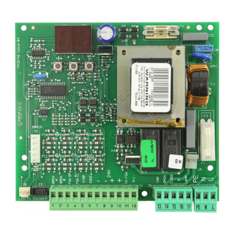
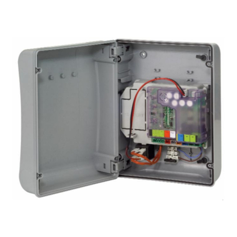
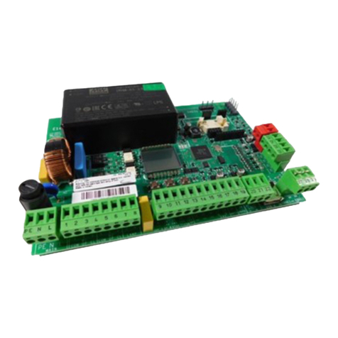
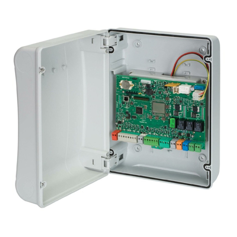
FAAC E145 User manual

E145
E145
Quick Guide
Quick Guide
www.faac.it
·
·
www.faacgroup.com
IT
Quick Guide
Quick Guide
- istruzioni di collegamento e pro-
grammazione dell’apparecchiatura per la messa in
funzione di un impianto tipo (per le illustrazioni fare
riferimento all’inserto centrale).
istruzioni complete e dichiarazione CE di con-
formità devono essere scaricate dal sito web
EN
Quick Guide
Quick Guide
- equipment connection and pro-
gramming instructions for operating a standard
system (per le illustrazioni fare riferimento all’inserto
centrale).
complete instructions and CE Declaration of Con-
formity must be downloaded from the web site
FR
Quick Guide
Quick Guide
- instructions pour la connexion et la
programmation de la platine pour la mise en fonction
d’une installation type (per le illustrazioni fare riferi-
mento all’inserto centrale).
les instructions complètes et déclaration CE de
conformité doivent être téléchargées du site web
DE
Quick Guide
Quick Guide
-
Anweisungen für denAnschluss und die Pro-
grammierungdesGerätszurInbetriebnahmeeinerStandardanlage
(per le illustrazioni fare riferimento all’inserto centrale).
Die vollständigen Anweisungen und die CE-
Konformitätserklärung müssen von der Website
heruntergeladen werden
ES
Quick Guide
Quick Guide
- instrucciones de conexión y progra-
mación del equipo para la puesta en funcionamiento
de una instalación tipo (per le illustrazioni fare riferi-
mento all’inserto centrale).
las instrucciones completas y la declaración CE
de conformidad deben descargarse del sitio web
NL
Quick Guide
Quick Guide
- instructies voor de aansluiting en
programmering van de apparatuur voor de inbedrijf-
stelling van een standaardinstallatie (per le illustra-
zioni fare riferimento all’inserto centrale).
de volledige instructies en de EG-verklaring van overeen-
stemming moeten van de website worden gedownload

E145 2 732783 - Rev.C
ITALIANO
Istruzioni originali
Tramite l’utilizzo della scheda elettronica di comando E145, e del nuovo encoder assoluto SAFEcoder
(Brevetto FAAC), si rende più agevole la messa a norma di impianti già installati senza necessità di
sostituire le automazioni esistenti.
Alimentazione primaria da rete Con alimentatore switching da 90 V~ a 260 V~;
50/60Hz
Potenza assorbita da rete stand By = 4W sleep < 2 W *MAX ~ 800 W
*
FUNZIONE ABILITABILE DA PC/MAC
Carico motori MAX 800 W
Alimentazione accessori 24 V"
Corrente MAX. accessori
+24V"MAX 500 mA BUS-2EASY MAX 500 mA
LOCK (FAAC) 12 V~ / 24
V"
LOCK (NON FAAC) 24 V"
500mA (3A picco)
Temperatura di funzionamento da -20°C a +55°C
Fusibili di protezione alimentazione F1 = F10 AH 250V
2. SEQUENZA DI INSTALLAZIONE
1. Rimuovere l’inserto immagini dal centro del manuale istruzione.
2. Cablare la scheda elettronica come descritto in figura :
• per il collegamento di fotocellule tradizionali vedere fig. ;
• per il collegamento di fotocellule bus vedere fig ;
• per il collegamento del modulo ricevente vedere fig. ;
• collegare eventuali encoder bus al morsetto J10 (fig. rif B).
3. Alimentare la scheda E145.
4. Verificare lo stato dei led su scheda E145, come descritto in figura .
5. In funzione dell’installazione, verificare che i led sugli encoder corrispondano a quelli descritti in
figura rif. A.
6. In base alle esigenze del cliente e dell’impianto, eseguire i settaggi della scheda elettronica, come
descritto al capitolo 3.
7. In funzione dei telecomandi presenti sull’impianto, eseguire la memorizzazione seguendo le
seguenti procedure:
• figura per telecomandi con codifica slh;
• figura per telecomandi con codifica rc/lc.
8. Ad ante chiuse eseguire l’apprendimento dei tempi di lavoro come descritto nel capitolo 4.
9. In funzione dei dispositivi installati regolare i parametri della scheda secondo le normative vigenti
(con SAFEcoder fare riferimento al capitolo 5).
10.Comandare un’apertura per verificare il corretto funzionamento dell’impianto.
1. CARATTERISTICHE TECNICHE
DESTINAZIONE D’USO: questa scheda elettronica è stata progettata e realizzata per la gestione di
cancelli battenti e/o scorrevoli, destinati al controllo di accessi veicolari e pedonali.

E145 3 732783 - Rev.C
ITALIANO
Istruzioni originali
3. PROGRAMMAZIONE
La programmazione è suddivisa in due livelli:
• programmazione BASE
• programmazione AVANZATA
Le fasi di programmazione sono (vedi Tab.):
1. entrare in programmazione (1A o 1B);
2. visualizzare i valori impostati e modificarli, se si desidera. La modifica dei valori è immediatamente
efficace, mentre la memorizzazione definitiva deve essere eseguita in uscita dalla programmazione (St);
3. uscire dalla programmazione mediante funzione St. Selezionare Yper SALVARE la configura-
zione appena eseguita, oppure no per USCIRE SENZA SALVARE modifiche.
È possibile USCIRE dalla programmazione in qualsiasi momento:
• premere e tenere premuto Fe poi anche
-
per passare direttamente a St.
F
+
-
/
R2
F
FF
-/
R2
+/
R1
F
F
+
+/
R1
F
+
+/
R1
❶❷❸
PROGRAMMAZIONE BASE
1A.
PREMERE ETENERE PREMUTO
F:
APPARE LA PRIMA FUNZIONE
1
LASCIARE F:
APPARE IL VALORE
DELLA FUNZIONE
CON
+
O
-
,
SCORRERE IVALORI
DISPONIBILI FINO AL
VALORE DESIDERATO
PREMERE F:
PER PASSARE
ALLA FUNZIONE
SUCCESSIVA
1
FUNZIONE St
(ULTIMA FUNZIONE BASE O
AVANZATA)
PROGRAMMAZIONE AVANZATA
1B. PREMERE ETENERE
PREMUTO FEPOI ANCHE
+
:
APPARE LA PRIMA FUNZIONE
1
LASCIARE ITASTI:
APPARE IL VALORE
DELLA FUNZIONE
SCEGLIERE YPER SALVARE
LA PROGRAMMAZIONE
OPPURE
SCEGLIERE no PER
ABBANDONARE LA
PROGRAMMAZIONE SENZA
SALVARE
1
1LA FUNZIONE RESTA VISUALIZZATA FINCHÉ SI MANTIENE PREMUTO
Tab. Fasi di programmazione

E145 4 732783 - Rev.C
ITALIANO
Istruzioni originali
3.1 PROGRAMMAZIONE BASE
Display
Funzione Base
Default
CF
TIPO MOTORI:
1Motori per cancelli battenti
2Motori per cancelli scorrevoli
PC Configurazione mista da PC/MAC (es: un battente e uno scorrevole)
dF
DEFAULT:
Yindica che tutti i valori impostati corrispondono ai default.
no indica che uno o più valori impostati sono diversi dai default.
Selezionare Yse si desidera ripristinare la configurazione di default.
Y
LO
LOGICHE DI FUNZIONAMENTO:
E, EP, S, SA, SP, A1, A, AP, At, b, bC, C, CU
Per il funzionamento delle logiche si veda il paragrafo dedicato.
E
PA
TEMPO DI PAUSA A (visualizzato solo con logiche Automatiche):
Regolabile da 00 a 9.5
minuti.
30
Pb
TEMPO DI PAUSA B (visualizzato solo con logiche Automatiche):
Regolabile da 00 a 9.5 minuti.
30
Mn
NUMERO MOTORI:
1= 1 motore
2= 2 motori
2
(battenti)
1
(scorrevoli)
F1
FORZA MOTORE 1:
01 = forza minima
50 = forza massima
25
F2
FORZA MOTORE 2 (visualizzato solo con funzione Mn = 2):
01 = forza minima
50 = forza massima
25
En
UTILIZZO ENCODER:
Y= encoder su entrambi i motori
no = encoder disabilitati
no
FA
FINECORSA IN APERTURA (visualizzato solo con funzione CF = 1o
CF = PC):
no = finecorsa in apertura disabilitati
01 = il finecorsa determina l’arresto movimentazione
02 = il finecorsa determina l’inizio rallentamento
no
FC
FINECORSA IN CHIUSURA (visualizzato solo con funzione CF = 1o
CF = PC):
no = finecorsa in chiusura disabilitati
01 = il finecorsa determina l’arresto movimentazione
02 = il finecorsa determina l’inizio rallentamento
no

E145 5 732783 - Rev.C
ITALIANO
Istruzioni originali
Display
Funzione Base
Default
Br
FRENATA ANTA SCORREVOLE (visualizzato solo con funzione CF = 2
o CF = PC):
00 = frenata disabilitata
10 = massimo tempo di frenata
05
Cd
RITARDO ANTA IN CHIUSURA (visualizzato solo con funzione Mn = 2):
Regolabile da 00 a 3
minuti.
05
bu
ISCRIZIONE DISPOSITIVI A BUS-2EASY:
1. Eseguire l’iscrizione: premere e tenere premuti i pulsanti
+
e
-
contempo-
raneamente per almeno 5 sec (durante questo tempo il display lampeggia).
2. A conferma del completamento dell’iscrizione, apparirà Y.
3. Rilasciare i pulsanti
+
e
-
. Il display visualizzerà lo stato dei dispositivi
BUS-2EASY.
Encoder 1: acceso = collegato e
iscritto correttamente
Encoder 2:acceso =
collegato e iscritto cor-
rettamente
Stato BUS:
sempre acceso
Fotocellula OPEN:
acceso = iscritta e impegnata
Fotocellule
in apertura: acceso = iscritte e impegnate
Fotocellule in chiusura:
acceso = iscritte e impegnate
Fotocellule in
apertura e in
chiusura:
acceso = iscritte e
impegnate
no
M2
AZIONAMENTO uomo presente MOTORE 2 (visualizzato solo con fun-
zione Mn = 2):
+
/
R
1
APRE (visualizzando oP) finché il pulsante viene tenuto premuto
-/
R2
CHIUDE (visualizzando cL) finché il pulsante viene tenuto premuto
--
M1
AZIONAMENTO uomo presente MOTORE 1:
+
/
R1
APRE (visualizzando oP) finché il pulsante viene tenuto premuto
-/
R2
CHIUDE (visualizzando cL) finché il pulsante viene tenuto premuto
--
tL
APPRENDIMENTO TEMPI DI LAVORO (SETUP):
Si veda il paragrafo relativo.
--

E145 6 732783 - Rev.C
ITALIANO
Istruzioni originali
Display
Funzione Base
Default
St
STATO DELL’AUTOMAZIONE:
1. impostare la scelta:
Yper SALVARE e USCIRE dalla programmazione
no per USCIRE dalla programmazione SENZA SALVARE
2. premere il tasto Fper conferma; al termine il display torna a visualizzare
lo stato dell’automazione:
Y
00 = CHIUSO
01 = APERTO
02 = Fermo poi “APRE”
03 = Fermo poi “CHIUDE”
04 = In “PAUSA”
05 = In fase di apertura
06 = In fase di chiusura
07 = FAIL SAFE in corso
08 =
verifica dispositivi BUS-2EASY in corso
09 = Prelampeggio poi “APRE”
10 = Prelampeggio poi “CHIUDE”
11 = Apertura in emergenza
12 = Chiusura in emergenza
HP = Hold position
3.2 PROGRAMMAZIONE AVANZATA
Display
Funzione Avanzata
Default
bo
TEMPO DI FORZA MASSIMA ALLO SPUNTO
01
cS
COLPO FINALE IN CHIUSURA (COLPO D’ARIETE) (NON visualizzato
con funzione FC = 1)
no
rS
COLPO D’INVERSIONE IN APERTURA (NON visualizzato con funzione
FA = 1)
no
Od
RITARDO ANTA IN APERTURA (visualizzato solo con funzione Mn = 2)
02
r1
RALLENTAMENTO ANTA 1:
Permette di regolare lo spazio di rallentamento come percentuale della corsa
totale dell’anta 1.
Regolabile da
00
a 99
%, a passi di 1%.
00 = nessun rallentamento
01 = spazio rallentamento minimo
99 = spazio rallentamento massimo
20
r2
RALLENTAMENTO ANTA 2 (visualizzato solo con funzione Mn = 2):
Permette di regolare lo spazio di rallentamento come percentuale della corsa
totale dell’anta 2.
Regolabile da
00
a 99
%, a passi di 1%.
00
= nessun rallentamento
01 = spazio rallentamento minimo
99
= spazio rallentamento massimo
20
PF
PRELAMPEGGIO
no
Ph
FOTOCELLULE IN CHIUSURA
no

E145 7 732783 - Rev.C
ITALIANO
Istruzioni originali
Display
Funzione Avanzata
Default
Ad
FUNZIONE ADMAP
no
EC
SENSIBILITÀ ANTISCHIACCIAMENTO (visualizzato solo con funzione En = Y):
Variando questa funzione si agisce sul tempo dopo il quale, in caso di ostacolo,
la scheda comanda l’inversione delle ante, o ne comanda l’arresto nel caso
le ante siano nello spazio di ricerca battuta (vedi funzione rB).
Il quarto ostacolo consecutivamente rilevato nella stessa direzione e posizione
viene definito come battuta e l’anta si arresta in quella posizione.
00 = minima sensibilità (tempo massimo prima dell’inversione)
10 = massima sensibilità (tempo minimo prima dell’inversione)
05
r8
ANGOLO RICERCA BATTUTA (visualizzato solo con funzione En = Y
e funzioni Fc ed FA = no o = 02):
Permette di regolare l’angolo di ricerca battuta entro il quale la scheda, se
trova un ostacolo o la battuta stessa, arresta il movimento senza invertire.
Regolabile da
0.3
a 20 gradi.
Da 0.3 a 9.9 gradi, la regolazione avviene a passi di 0.1 gradi.
Da 10 a 20 gradi, la regolazione avviene a passi di 1 grado.
4.0
tA
TEMPO DI LAVORO AGGIUNTIVO (visualizzato solo con funzione En
= no e funzioni Fc ed FA = no o 02)
03
o1
OUT 1:
default 00 = sempre attiva. Uscita configurabile da 00 a 17
00
t1
TEMPORIZZAZIONE OUT 1 (visualizzato solo con funzione o1 = 03
o o1 = 14)
02
o2
OUT 2:
default 02 = LAMPADA SPIA - Vedi le opzioni come in o1.
02
t2
TEMPORIZZAZIONE OUT 2 (visualizzato solo con funzione o2 = 03
o o2 = 14):
Regolabile come t1.
02
AS
RICHIESTA MANUTENZIONE - CONTACICLI (abbinata alle due funzioni
successive)
no
nc
PROGRAMMAZIONE CICLI (MIGLIAIA)
00
nd
PROGRAMMAZIONE CICLI (DECINE)
00
St
STATO DELL’AUTOMAZIONE:
vedi ST Funzione Base
Y

E145 8 732783 - Rev.C
ITALIANO
Istruzioni originali
4. APPRENDIMENTO DEI TEMPI - SETUP
Quando viene alimentata la scheda, se non è mai stato eseguito un SETUP, o se la scheda lo richiede,
sul display lampeggia la sigla S0 ad indicare che è necessario eseguire il SETUP.
Durante il SETUP vegono sempre iscritti gli accessori BUS-2EASY collegati. Gli enco-
der BUS-2EASY iscritti da SETUP devono essere poi abilitati mediante funzione En
(Programmazione BASE).
Eseguire la procedura di SETUP come segue:
Durante il SETUP le sicurezze sono disattivate! Eseguire pertanto l’operazione evitando
qualsiasi transito nella zona di movimentazione delle ante.
In caso di installazione e impianto senza l’utilizzo di encoder, saranno necessarie le
battute meccaniche di arresto delle ante.
1. Entrare in programmazione BASE
fino alla funzione tL, dove al rilascio del pulsante F apparirà
la sigla
--
--.
2. Verificare che le ante del cancello siano chiuse. In caso contrario agire come segue:
- Premere e tenere premuto il tasto -/R2 per chiudere l’anta 2
- Premere e tenere premuto il tasto +/R1 per chiudere l’anta 1
Nel caso in cui la pressione dei tasti +/R1 e/o -/R2 comandi l’apertura dell’anta
corrispondente, è necessario togliere tensione ed invertire sulla morsettiera
J2 i cavi delle fasi del motore corrispondente (morsetti 2-3 per motore anta 1 e
morsetti 5-6 per motore anta 2).
3. Con le ante del cancello chiuse, lanciare la procedura di SETUP tenendo premuti i pulsanti
+
e
-
fino al lampeggio della scritta S1 sul display (circa 3 sec).
4. Rilasciare i pulsanti
+
e
-
. L’anta 1 inizia una movimentazione di apertura.
Funzionamento SENZA Encoder
Fermare il movimento dando un impulso di
OPEN A non appena l’anta 1 raggiunge la
battuta di arresto.
Funzionamento CON Encoder
L’anta 1 si fermerà non appena avrà raggiunto la
battuta di arresto. In mancanza della battuta di
arresto fermare la movimentazione dell’anta nel
punto desiderato dando un impulso di OPEN A
5. Sul display lampeggia S2 (solo se sono stati selezionati 2 motori): l’anta 2 inizia l’apertura.
Funzionamento SENZA Encoder
Fermare il movimento dando un impulso di
OPEN A non appena l’anta 2 raggiunge la
battuta di arresto.
Funzionamento CON Encoder
L’anta 2 si fermerà non appena avrà raggiun-
to la battuta di arresto. In mancanza della
battuta di arresto fermare la movimentazione
dell’anta nel punto desiderato dando un
impulso di OPEN A
6. Sul display lampeggia S3 (solo se sono stati selezionati 2 motori): l’anta 2 inizia la chiusura.
Funzionamento SENZA Encoder
Fermare il movimento dando un impulso di
OPEN A non appena l’anta 2 raggiunge la
battuta di arresto.
Funzionamento CON Encoder
L’anta 2 si fermerà non appena avrà raggiunto la
battuta di arresto. In mancanza della battuta di
arresto fermare la movimentazione dell’anta nel
punto desiderato dando un impulso di OPEN A.
7. Sul display lampeggia S4 : l’anta 1 inizia la chiusura.

E145 9 732783 - Rev.C
ITALIANO
Istruzioni originali
Funzionamento SENZA Encoder
Fermare il movimento dando un impulso di
OPEN A non appena l’anta 1 raggiunge la
battuta di arresto.
Funzionamento CON Encoder
L’anta 1 si fermerà non appena avrà raggiunto la
battuta di arresto. In mancanza della battuta di
arresto fermare la movimentazione dell’anta nel
punto desiderato dando un impulso di OPEN A
8. Automaticamente la scheda esce dal menù di programmazione visualizzando lo stato dell’auto-
mazione (sigla 00) a conferma della corretta conclusione della procedura di SETUP. Nel caso la
procedura non si sia conclusa regolarmente sul display lampeggerà la sigla S0 ad indicare che
è necessario eseguire una nuova procedura di SETUP.
È possibile configurare e modificare gli spazi di rallentamento agendo da display
sui parametri r1 e r2 (vedi Programmazione Avanzata) senza dover ripetere il
SETUP.
In caso di presenza dei finecorsa fare riferimento alle istruzioni complete.
5. PARAMETRI UTILI PER LA PROTEZIONE DEL RISCHIO DI IMPATTO/
SCHIACCIAMENTO DEL BORDO PRINCIPALE
PARAMETRO FUNZIONE
F1
Permette di regolare la forza di spinta statica del motore 1.
NOTA: Per operatori oleodinamici impostare il valore di forza al massimo e rego-
lare la forza tramite le viti di by pass
F2
Permette di regolare la forza di spinta statica del motore 2.
NOTA: Per operatori oleodinamici impostare il valore di forza al massimo e rego-
lare la forza tramite le viti di by pass
En
Abilita la lettura degli encoder da parte della scheda elettronica garantendo l’in-
versione in presenza di ostacoli (impostare EN=Y).
Cd
Permette di modificare il ritardo in chiusura del motore 1 ottenendo uno sfasamento
tra le due ante e riducendo il rischio di schiacciamento fra le due ante in movimento.
r1
Permette di adattare lo spazio di velocità rallentata dell’anta 1. L’impatto a veloci-
tà rallentata permette di diminuire la forza dinamica.
r2
Permette di adattare lo spazio di velocità rallentata dell’anta 2. L’impatto a veloci-
tà rallentata permette di diminuire la forza dinamica.
EC
Permette di regolare la sensibilità dell’ inversione su ostacolo.
rB
Permette di modificare lo spazio precedente le battute meccaniche, nel quale la
scheda non effettua inversioni (impostare un valore compreso tra 1 e 49 mm).
6. LOGICHE DI FUNZIONAMENTO
Questa tabella riassume le logiche di funzionamento.
Per la descrizione di ciascuna in dettaglio, vedi le istruzioni complete.
LOGICA Stato automatismo:
fermo Stato automatismo:
in movimento Stato:
intervento fotocellula
ESemiautoma-
tica un impulso di OPEN
apre il cancello e al
successivo chiude
Un impulso di OPEN
in apertura blocca e in
chiusura riapre
Le fotocellule durante il moto
invertono
EP Semiautoma-
tica passo-
passo
un impulso di OPEN
apre il cancello e al
successivo chiude
Un impulso di OPEN
durante il moto blocca Le fotocellule durante il moto
invertono

E145 10 732783 - Rev.C
ITALIANO
Istruzioni originali
LOGICA Stato automatismo:
fermo Stato automatismo:
in movimento Stato:
intervento fotocellula
SAutomatica
Sicurezza un impulso di OPEN
apre il cancello e dopo
il tempo pausa chiude
automaticamente
Un impulso di OPEN
durante la pausa chiude
e durante il moto inverte
Le fotocellule di chiusura fanno
richiudere durante la pausa;
prenotano la chiusura duran-
te un’apertura e durante una
chiusura invertono facendo poi
chiudere subito
SA Automatica
Sicurezza
con inversio-
ne in pausa
un impulso di OPEN
apre il cancello e dopo
il tempo pausa chiude
automaticamente
Un impulso di OPEN
durante la pausa
chiude; in apertura non
ha effetto; in chiusura
inverte
Le fotocellule di chiusura ricari-
cano la pausa
SP Automatica
Sicurezza
passo-passo un impulso di OPEN
apre il cancello e dopo
il tempo pausa chiude
automaticamente
Un impulso di OPEN
durante la pausa chiu-
de e durante il moto
blocca
Le fotocellule di chiusura fanno
richiudere durante la pausa;
prenotano la chiusura duran-
te un’apertura e durante una
chiusura invertono facendo poi
chiudere subito
A1 Automatica 1 un impulso di OPEN
apre il cancello e dopo
il tempo pausa chiude
automaticamente
Un impulso di OPEN
durante l’apertura viene
ignorato, durante la pau-
sa la ricarica e durante la
chiusura riapre
Le fotocellule di chiusura fanno
richiudere durante la pausa;
prenotano la chiusura duran-
te un’apertura e durante una
chiusura invertono facendo poi
chiudere subito
AAutomatica un impulso di OPEN
apre il cancello e dopo
il tempo pausa chiude
automaticamente
Un impulso di OPEN
durante l’apertura viene
ignorato, durante la pau-
sa la ricarica e durante la
chiusura riapre
Le fotocellule di chiusura ricari-
cano la pausa
AP Automatica
passo-passo un impulso di OPEN
apre il cancello e dopo
il tempo pausa chiude
automaticamente
Un impulso di OPEN
durante l’apertura e la
pausa blocca; in chiusu-
ra inverte
Le fotocellule di chiusura ricari-
cano la pausa
bSemiauto-
matica “b”
(gli ingressi
OPEN-B
diventano
CLOSE)
logica a due comandi
separati: impulso
OPEN-A apre; impul-
so CLOSE chiude
Un impulso di OPEN-
A durante la chiusura
apre, un impulso di
CLOSE durante l’aper-
tura chiude
Le fotocellule durante il moto
invertono
bC Logica Mista
(in apertura
“b”, in chiusu-
ra “C”) (gli in-
gressi OPEN-
B diventano
CLOSE)
logica a due coman-
di separati: impulso
OPEN-Aapre; CLOSE
mantenuto chiude
Un impulso di OPEN-
A durante la chiusu-
ra apre, un comado di
CLOSE durante l’aper-
tura chiude
Le fotocellule durante il moto
invertono
CUomo presen-
te (gli ingressi
OPEN-B di-
ventano CLO-
SE)
logica a due coman-
di separati: OPEN-A
mantenuto apre; CLO-
SE mantenuto chiude
Un comando di OPEN-
A durante la chiusu-
ra apre, un comado di
CLOSE durante l’aper-
tura chiude
Le fotocellule durante il moto
invertono

E145 2 732783 - Rev.C
ENGLISH
Translation of the original instructions
Thanks to the electronic board E145 and the new SAFEcoder absolute encoder (FAAC Patented), it
is easier to adapt existing systems in accordance with the law without having to replace the existing
automated systems.
Mains primary power supply With switching power supply from 90 V~ to 260 V~;
50/60 Hz
Power absorbed from mains Stand By = 4W Sleep < 2 W *MAX ~ 800 W
*CAN BE ACTIVATED VIA PC/MAC
MAX motor load 800 W
Accessories power supply 24 V"
MAX Accessories current
+24V"MAX 500 mA BUS-2EASY MAX 500 mA
LOCK (FAAC) 12 V~ / 24
V"
LOCK (NON FAAC) 24
V" 500mA (3A peak)
Operating temperature -20°C to +55°C
Power supply fuses F1 = F10 AH 250V
2. INSTALLATION SEQUENCE
1. Remove the diagram insert from the centre of the user manual.
2. Wire the electronic board as described in figure :
• refer to fig. to connect traditional photocells;
• refer to fig. to connect Bus photocells;
• refer to fig. to connect the receiver module;
• connect any Bus encoders to terminal J10 (fig. ref. B).
3. Power the board E145.
4. Verify the status of the LEDs on board E145, as described in figure .
5. Depending on the installation, verify that the LEDs on the encoders correspond to those described
in figure ref. A.
6. Set the electronic board, according to the customer and system requirements and as described in
Chapter 3.
7. Implement the storing operations according to the remote controls on the system, by following
the procedures below:
• figure for SLH encoded remote controls;
• figure for RC/LC encoded remote controls.
8. Close the doors to perform the work time learning operations as described in Chapter 4.
9. Set the parameters of the board according to the installed devices and the regulations in force
(refer to Chapter 5 for SAFEcoder).
10.Implement an opening to verify that the system works correctly.
1. TECHNICAL SPECIFICATIONS
INTENDED USE: this electronic board is designed and built to control swing and/or sliding gates,
which control access of vehicles and pedestrians.

E145 3 732783 - Rev.C
ENGLISH
Translation of the original instructions
3. PROGRAMMING
Programming is divided into 2 levels:
• BASIC programming
• ADVANCED programming
The programming phases are (refer to Tab.):
1. access PROGRAMMING (1A or 1B);
2. view the set values and modify them, if necessary. Modifying the values is immediately effective, whereas
the final saving operation must be implemented on exiting the programming section (St);
3. exit programming via the St function. Select Yto SAVE the configuration that has just been
implemented or no to EXIT WITHOUT SAVING the changes.
You can EXIT programming at any time:
• keep Fpressed and then also
-
to switch directly to St.
F
+
-
/
R2
F
FF
-/
R2
+/
R1
F
F
+
+/
R1
F
+
+/
R1
❶❷❸
BASIC PROGRAMMING
1A.
KEEP FPRESSED:
THE 1ST FUNCTION
APPEARS1
RELEASE F:
THE FUNCTION
VALUE IS
DISPLAYED
USE
+
OR
-
TO SCROLL THE
AVAILABLE VALUES
UP TO THE DESIRED
ONE AND
PRESS F:
TO GO TO
THE NEXT
FUNCTION1
FUNCTION St
(LAST BASIC OR ADVANCED
FUNCTION)
ADVANCED PROGRAMMING
1B. KEEP FPRESSED AND
THEN
+
TOO:
THE 1ST FUNCTION
APPEARS1
RELEASE THE
BUTTONS:
THE FUNCTION
VALUE IS DISPLAYED
SELECT YTO SAVE THE
PROGRAMMING
OR
SELECT no TO EXIT THE
PROGRAMMING WITHOUT
SAVING
1
1THE FUNCTION IS DISPLAYED FOR AS LONG AS THE BUTTON IS PRESSED
Tab. Programming phases

E145 4 732783 - Rev.C
ENGLISH
Translation of the original instructions
3.1 BASIC PROGRAMMING
Display
Basic Function
Default
CF
MOTOR TYPE:
1Motors for swing gates
2Motors for sliding gates
PC Mixed configuration from a PC/MAC (e.g.: one swing and one slide)
dF
DEFAULT:
YIndicates that all the set values are default values.
no Indicates that at last 1 set value is different from the default values.
Select Yif you wish to restore the default configuration.
Y
LO
OPERATING LOGIC:
E, EP, S, SA, SP, A1, A, AP, At, b, bC, C, CU
Refer to the specific paragraph for a description of the operating logics.
E
PA
PAUSE A TIME (only displayed with Automatic logic):
Can be adjusted from 00 to 9.5 minutes.
30
Pb
PAUSE B TIME (only displayed with Automatic logic):
Can be adjusted from 00 to 9.5 minutes.
30
Mn
NUMBER OF MOTORS:
1= 1 motor
2= 2 motors
2
(swing)
1
(sliding)
F1
MOTOR 1 POWER:
01 = minimum power
50 = maximum power
25
F2
MOTOR 2 POWER (only displayed with the Mn = 2function):
01 = minimum power
50 = maximum power
25
En
ENCODER USE:
Y= encoders on both motors
no = disabled encoders
no
FA
LIMIT SWITCH WHEN OPENING (only displayed with the CF = 1or CF
= PC function):
no = opening limit switches disabled
01 = the limit switch determines when the movement is stopped
02 = the limit switch determines when deceleration begins
no
FC
LIMIT SWITCH WHEN CLOSING (only displayed with the CF = 1or CF
= PC function):
no = closing limit switches disabled
01 = the limit switch determines when the movement is stopped
02 = the limit switch determines when deceleration begins
no

E145 5 732783 - Rev.C
ENGLISH
Translation of the original instructions
Display
Basic Function
Default
Br
SLIDING LEAF BRAKING (only displayed with the CF = 2or CF = PC
function):
00 = braking disabled
10 = maximum braking time
05
Cd
LEAF CLOSING DELAY (only displayed with the Mn = 2function):
Can be adjusted from 00 to 3minutes.
05
bu
BUS-2EASY DEVICE REGISTRATION:
1. Register: keep
+
and
-
pressed simultaneously for at least 5 s (the display
flashes during this time).
2. Ywill appear once confirmation of the completed registration is given.
3. Release
+
and
-
. The status of the BUS-2EASY devices will appear on
the display.
Encoder 1: ON = connected and
registered correctly
Encoder 2: ON =
connected and
registered
correctly
BUS Status:
Always ON
OPEN Photocell:
ON = registered and committed
Opening
and closing photocells: ON = registered and committed
Closing photocells:
ON = registered and committed
Opening and
closing photo-
cells:
ON = registered
and committed
no
M2
MOTOR 2 dead-man DRIVE mode (only displayed with the Mn = 2
function):
+
/
R
1
OPENS (displaying
oP) for as long as the button is pressed
-/
R2
CLOSES (displaying cL) for as long as the button is pressed
--
M1
MOTOR 1 dead-man DRIVE mode:
+
/
R1
OPENS (displaying
oP) for as long as the button is pressed
-/
R2
CLOSES (displaying cL) for as long as the button is pressed
--
tL
WORK TIME LEARNING OPERATIONS (SET UP):
Refer to the relative paragraph.
--

E145 6 732783 - Rev.C
ENGLISH
Translation of the original instructions
Display
Basic Function
Default
St
STATUS OF THE AUTOMATED SYSTEM:
1. set the selection:
Y to SAVE and EXIT programming
no to EXIT programming WITHOUT SAVING
2. press Fto confirm; when completed, the status of the automated system will
appear on the display once again:
Y
00 = CLOSED
01 = OPEN
02 = Stationary and then “OPENS”
03 = Stationary and then “CLOSES”
04 = In “PAUSE”
05 = Opening
06 = Closing
07 = FAIL SAFE in progress
08 =
Verifying BUS-2EASY devices
09 = Pre-flashes and then “OPENS”
10 = Pre-flashes and then “CLOSES”
11 = Emergency open
12 = Emergency close
HP = Hold position
3.2 ADVANCED PROGRAMMING
Display
Advanced Function
Default
bo
TIME OF MAXIMUM POWER AT START-UP
01
cS
FINAL STROKE WHEN CLOSING (FLUID HAMMER) (NOT displayed with
the FC = 1function)
no
rS
REVERSE STROKE WHEN OPENING (NOT displayed with the FA = 1function)
no
Od
LEAF OPENING DELAY (only displayed with the Mn = 2function)
02
r1
LEAF 1 DECELERATION:
The deceleration space can be adjusted as a percentage of the total travel
of leaf 1.
Adjustable from 00 to 99%, in 1% steps.
00 = no deceleration
01 = minimum deceleration space
99 = maximum deceleration space
20
r2
LEAF 2 DECELERATION (only displayed with the Mn = 2function):
The deceleration space can be adjusted as a percentage of the total travel
of leaf 2.
Adjustable from 00 to 99%, in 1% steps.
00 = no deceleration
01 = minimum deceleration space
99 = maximum deceleration space
20
PF
PRE-FLASHING
no
Ph
CLOSING PHOTOCELLS
no

E145 7 732783 - Rev.C
ENGLISH
Translation of the original instructions
Display
Advanced Function
Default
Ad
ADMAP FUNCTION
no
EC
ANTI-CRUSHING SENSITIVITY (only displayed with the En = Yfunction):
Varying this function alters the time after which the board commands the
leaves to reverse their direction in case of an obstacle or to stop if they are
in the contact point search space (refer to the rB function).
The fourth consecutive obstacle detected in the same direction and position
will be defined as a contact point and the leaf will stop in this position.
00 = minimum sensitivity (maximum time before reversal)
10 = maximum sensitivity (minimum time before reversal)
05
r8
MECHANICAL STOP SEARCH ANGLE (only displayed with the En = Y
function and Fc and FA = no or = 02 functions):
The mechanical stop search angle within which the board stops the movement without
reversing if an obstacle is encountered or the mechanical stop itself can be adjusted.
Can be adjusted from 0.3 to 20 degrees.
0.1 degree steps apply when adjusting between 0.3 and 9.9 degrees.
1 degree steps apply when adjusting between 10 and 20 degrees.
4.0
tA
ADDITIONAL OPERATING TIME only displayed with the En = no and
Fc and FA = no or 02 functions)
03
o1
OUT 1:
Default 00 = always active. Output can be configured from 00 to 17.
00
t1
OUT 1 TIMING (only displayed with the o1 = 03 or o1 = 14 function)
02
o2
OUT 2:
Default 02 = LED - Refer to the options in o1.
02
t2
OUT 2 TIMING (only displayed with the o2 = 03 or o2 = 14 function):
Adjustable like t1.
02
AS
MAINTENANCE REQUEST - CYCLE COUNTER (linked to the subsequent
2 functions)
no
nc
CYCLE PROGRAMMING (THOUSANDS)
00
nd
CYCLE PROGRAMMING (TENS)
00
St
STATUS OF THE AUTOMATED SYSTEM:
Refer to ST Basic Function.
Y

E145 8 732783 - Rev.C
ENGLISH
Translation of the original instructions
4. TIME LEARNING - SET-UP
When the board is powered, if a SET-UP has never been performed or if the board requires it, S0
flashes on the display indicating that a SET-UP must be performed.
The connected accessories are always registered during SET-UP.BUS-2EASY The
BUS-2EASY encoders registered during the SET-UP must then be enabled via the En
function (BASIC Programming).
Perform the SET-UP as follows:
All safety devices are disabled during SET-UP! Therefore, perform the operation and
prevent any transit in the leaf movement area.
If a system without an encoder is installed, the leaves will require mechanical stops.
1. Access BASIC programming and go to the tL function, and
--
-- will appear when the F button
is released.
2. Verify that the gate leaves are closed. Otherwise, proceed as follows:
- Keep the -/R2 button pressed to close leaf 2
- Keep the +/R1 button pressed to close leaf 1
If the corresponding leaf opens when the +/R1 and/or -/R2 buttons are pressed,
disconnect the power and invert the phase wires of the corresponding motor
on the J2 terminal board, (terminals 2-3 for the leaf 1 motor and terminals 5-6
for the leaf 2 motor).
3. With the gate leaves closed, launch the SET-UP procedure by keeping buttons
+
and
-
pressed
until S1 flashes on the display (approx. 3 sec).
4. Release
+
and
-
. Leaf 1 begins its opening movement.
Operation WITHOUT Encoder
Stop the movement by sending an OPEN
A pulse as soon as leaf 1 reaches the
mechanical stop.
Operation WITH Encoder
Leaf 1 will stop as soon as it reaches the me-
chanical stop. If there is no mechanical stop,
stop the leaf movement at the desired point by
sending an OPEN A pulse.
5. S2 will flash on the display (only if 2 motors have been selected): leaf 2 begins its opening
movement.
Operation WITHOUT Encoder
Stop the movement by sending an OPEN
A pulse as soon as leaf 2 reaches the
mechanical stop.
Operation WITH Encoder
Leaf 2 will stop as soon as it reaches the
mechanical stop. If there is no mechanical
stop, stop the leaf movement at the desired
point by sending an OPEN A pulse.
6. S3 will flash on the display (only if 2 motors have been selected): leaf 2 begins its closing movement.
Operation WITHOUT Encoder
Stop the movement by sending an OPEN
A pulse as soon as leaf 2 reaches the
mechanical stop.
Operation WITH Encoder
Leaf 2 will stop as soon as it reaches the me-
chanical stop. If there is no mechanical stop,
stop the leaf movement at the desired point by
sending an OPEN A pulse.
7. S4 will flash on the display: leaf 1 will begin its closing movement.

E145 9 732783 - Rev.C
ENGLISH
Translation of the original instructions
Operation WITHOUT Encoder
Stop the movement by sending an OPEN
A pulse as soon as leaf 1 reaches the
mechanical stop.
Operation WITH Encoder
Leaf 1 will stop as soon as it reaches the me-
chanical stop. If there is no mechanical stop,
stop the leaf movement at the desired point by
sending an OPEN A pulse.
8. The board will automatically exit the programming menu and will display the status of the automated
system (00) as confirmation that the SET-UP procedure has been completed correctly. If the
procedure is not completed correctly, S0 will start flashing on the display, indicating that a new
SET-UP procedure must be performed.
The deceleration spaces can be configured and modified from the r1 and r2
parameters on the display (refer to Advanced Programming) without having to
repeat the SET-UP.
Refer to the complete instructions if there are limit switches.
5. USEFUL PARAMETERS TO PROTECT AGAINST THE RISK OF IMPACT/
CRUSHING ON THE MAIN EDGE
PARAMETER FUNCTION
F1
Allows the static thrust force of motor 1 to be adjusted.
NOTE: For hydraulic operators, set the force value to maximum and adjust it via
the bypass screws.
F2
Allows the static thrust force of motor 2 to be adjusted.
NOTE: For hydraulic operators, set the force value to maximum and adjust it via
the bypass screws.
En
Enables the encoders to be read by the electronic board, thereby guaranteeing
that inversion occurs in the presence of obstacles (set EN=Y).
Cd
Allows the closing delay of motor 1 to be modified in order to obtain a phase shift
between the two leaves and reducing the risk of crushing between the two moving
leaves.
r1
Allows the space of reduced speed of leaf 1 to be adapted. The impact at slow
speed allows the dynamic force to be reduced.
r2
Allows the space of reduced speed of leaf 2 to be adapted. The impact at slow
speed allows the dynamic force to be reduced.
EC
Allows the obstacle inversion sensitivity to be adjusted.
rB
Allows the space before the mechanical stops in which the board does not per-
form inversions to be modified (set a value between 1 and 49 mm).
6. OPERATING LOGIC
This table summarises the operating logic.
Refer to the complete instructions for a detailed description of each.
LOGIC
Status of the automated
system:
stopped
Status of the automated
system:
in motion
Status:
photocell action
E
Semi-automatic An OPEN pulse opens the
gate and the following one
closes it
An OPEN pulse stops the
gate when opening and
reopens when the gate is
closing
The photocells invert during motion

E145 10 732783 - Rev.C
ENGLISH
Translation of the original instructions
LOGIC
Status of the automated
system:
stopped
Status of the automated
system:
in motion
Status:
photocell action
EP
Semi-automatic,
Step-by-Step An OPEN pulse opens the
gate and the following one
closes it
An OPEN pulse blocks
during motion The photocells invert during motion
S
Automatic
Safety An OPEN pulse opens
the gate and closes
automatically after the
pause time
An OPEN pulse closes the
gate during the pause and
inverts during motion
The closing photocells close the gate
once again during the pause; they
memorise closure when the gate
opens and immediately invert when
closing
SA
Automatic
Safety with
inversion during
the pause
An OPEN pulse opens
the gate and closes
automatically after the
pause time
An OPEN pulse closes
during the pause; has no
effect when the gate opens
and inverts when it closes
The closing photocells reapply the
pause
SP
Automatic Step-
by-Step Safety An OPEN pulse opens
the gate and closes
automatically after the
pause time
An OPEN pulse closes the
gate during the pause and
blocks during motion
The closing photocells close the gate
once again during the pause; they
memorise closure when the gate
opens and immediately invert when
closing
A1
Automatic 1 An OPEN pulse opens
the gate and closes
automatically after the
pause time
An OPEN pulse is ignored
when the gate opens, is
reapplied during the pause
and reopens when the gate
closes
The closing photocells close the gate
once again during the pause; they
memorise closure when the gate
opens and immediately invert when
closing
A
Automatic An OPEN pulse opens
the gate and closes
automatically after the
pause time
An OPEN pulse is ignored
when the gate opens, is
reapplied during the pause
and reopens when the gate
closes
The closing photocells reapply the
pause
AP
Automatic, Step-
by-Step An OPEN pulse opens
the gate and closes
automatically after the
pause time
An OPEN pulse blocks
when the gate opens and
during the pause and inverts
when it closes
The closing photocells reapply the
pause
b
Semi-automatic
“b” (OPEN-B
inputs become
CLOSE)
Logic with two separate
commands: OPEN-A
pulse opens; CLOSE
pulse closes
An OPEN-A pulse opens
when the gate closes, a
CLOSE pulse closes when
it opens
The photocells invert during motion
bC
Mixed Logic
("b" in opening;
"c" in closing),
OPEN-B
inputs become
CLOSE)
Logic with two separate
commands: OPEN-A
pulse opens; pressed
CLOSE closes
An OPEN-A pulse opens
when the gate closes, a
CLOSE pulse closes when
it opens
The photocells invert during motion
C
Dead-man
(OPEN-B
inputs become
CLOSE)
Logic with two separate
commands: pressed
OPEN-A opens; pressed
CLOSE closes
An OPEN-A pulse opens
when the gate closes; a
CLOSE pulse closes when
it opens
The photocells invert during motion

E145 2 732783 - Rev.C
FRANÇAIS
Traduction de la notice originale
Grâce à l'utilisation de la carte électronique de commande E145, et du nouvel encodeur absolu
SAFEcoder (Brevet FAAC), la mise aux normes d'installations déjà montées est plus simple sans
que le remplacement des automations existantes soit nécessaire.
Alimentation primaire en provenance de
réseau
Avec alimentateur switching de 90 V~ à 260 V~; 50/60
Hz
Puissance absorbée en provenance de
réseau
stand By = 4 W sleep < 2 W *MAX ~ 800 W
*FONCTION ACTIVABLE DEPUIS PC/MAC
Charge des moteurs MAX 800 W
Alimentation des accessoires 24 V"
Courant MAX accessoires
+ 24 V"MAX 500 mA BUS-2EASY MAX 500 mA
LOCK (FAAC) 12 V~ / 24
V"
LOCK (PAS FAAC) 24 V"
500mA (3A pic)
Température d'utilisation de -20 °C à +55 °C
Fusibles de protection de l'alimentation F1 = F10 AH 250 V
2. ORDRE D'INSTALLATION
1. Retirer l'encart des images situé au centre du manuel d'instruction.
2. Câbler la carte électronique comme décrit sur la figure :
• pour le branchement de photocellules traditionnelles, voir la fig.
• pour le branchement de photocellules bus, voir la fig.
• pour le branchement du module de réception, voir la fig.
• brancher les éventuels encodeurs bus au bornier J10 (fig. réf. B).
3. Mettre la carte sous tension E145.
4. Vérifier l'état des leds sur la carte E145, comme décrit sur la figure .
5. En fonction de l'installation, vérifier que les leds sur les encodeurs correspondent à celles décrites
sur la figures réf. A.
6. Selon les besoins du client et de l'installation, effectuer les réglages de la carte électronique, comme
décrit au chapitre 3.
7. En fonction des télécommandes présentes sur l'installation, effectuer la mémorisation en suivant
les procédures suivantes :
• figure pour télécommandes avec codage slh ;
• figure pour télécommandes avec codage rc/lc.
8. Lorsque le vantail est fermé, effectuer l'apprentissage des temps de fonctionnement comme décrit
dans le chapitre 4.
9. En fonction des dispositifs installés, régler les paramètres de la carte selon les réglementations
en vigueur (avec SAFEcoder se référer au chapitre 5).
10.Commander une ouverture afin de vérifier le bon fonctionnement de l'installation.
1. CARACTÉRISTIQUES TECHNIQUES
USAGE PRÉVU : cette carte électronique a été conçue et réalisée pour la gestion des portails battants
et/ou coulissants destinés au contrôle des accès de véhicules et piétons.
Other manuals for E145
4
Table of contents
Languages:
Other FAAC Controllers manuals
Popular Controllers manuals by other brands

Taco
Taco TS-1P Installation & operation guide

Trox
Trox VFC series operating manual

Samson
Samson TROVIS 5400 Series Mounting and operating instructions

IWAKI AMERICA
IWAKI AMERICA Walchem W900 Quick programming guide

IR Robot
IR Robot mightyZAP user manual

Vestamatic
Vestamatic MC P4 LoVo Installation and operating instructions