manuals.online logo
Brands
  1. Home
  2. •
  3. Brands
  4. •
  5. FAAC
  6. •
  7. Other
  8. •
  9. FAAC 620 STANDARD User manual

FAAC 620 STANDARD User manual

620 640 642
620 640 642
ASSEMBLAGGIO SBARRA RETTANGOLARE PER MOD. :
620 STANDARD - 620 RAPIDA - 620 SR - 642 STD/40 - 642
R/40.
RECTANGULAR BEAM ASSEMBLY FOR MOD. :
620 STANDARD - 620 RAPID - 620 SR - 642 STD/40 - 642
R/40.
ASSEMBLAGE BARRE RECTANGULAIRE POUR MOD. :
620 STANDARD - 620 RAPIDE - 620 SR - 642 STD/40 - 642 R/40.
MONTAGE DES RECHTECKIGEN BALKENS FÜR MOD. :
620 STANDARD - 620 SCHNELL - 620 SR - 642 STD/40 - 642
R/40.
ENSAMBLE BARRA RECTANGULAR PARA EL MOD. :
620 ESTANDAR – 620 RAPIDA – 620 SR – 642 STD/40 – 642
R/40.
ASSEMBLAGE RECHTHOEKIGE MAST VOOR MOD.:
620 STANDARD - 620 RAPIDA - 620 SR- 642 STD/40 - 642
R/40.

ASSEMBLAGGIO SBARRA TONDA PER MOD. :
620 STD - 620 RAPIDA - 620 SR - 642 STD/40 - 642 R/40.
ROUND BEAM ASSEMBLY FOR MOD. :
620 STD - 620 RAPID - 620 SR - 642 STD/40 - 642 R/40.
ASSEMBLAGE BARRE RONDE POUR MOD. :
620 STD - 620 RAPIDE - 620 SR - 642 STD/40 - 642 R/40.
MONTAGE DES RUNDEN BALKENS FÜR MOD. :
620 STD - 620 SCHNELL - 620 SR - 642 STD/40 - 642 R/40.
ENSAMBLE BARRA REDONDA PARA EL MOD. :
620 ESTD – 620 RAPIDA – 620 SR – 642 STD/40 – 642 R/40.
ASSEMBLAGE RONDE MAST VOOR MOD.:
620 STD - 620 RAPIDA - 620 SR - 642 STD/40 - 642 R/40.



732327 Rev. E
ASSEMBLAGGIO SBARRA RETTANGOLARE PER
MOD. : 640 - 642/70.
RECTANGULAR BEAM ASSEMBLY FOR MOD. :
640 - 642/70.
ASSEMBLAGE BARRE RECTANGULAIRE POUR MOD.
: 640 - 642/70.
MONTAGE DES RECHTECKIGEN BALKENS FÜR
MOD. : 640 - 642/70.
ENSAMBLE BARRA RECTANGULAR PARA EL MOD.
: 640 - 642/70.
ASSEMBLAGE RECHTHOEKIGE MAST VOOR MOD.
: 640 - 642/70.

620 SR I
GB
F
D
E
NL
I
GB
F
D
E
NL
I
GB
F
D
E
NL
Fig. 1
Abb. 1
732294 Rev. D
B
A
620 642
620 642

Fig. 2
Abb. 2
Fig. 3
Abb. 3
ASSEMBLAGGIO SBARRA TONDA PIVOTTANTE PER MOD. :
620 STANDARD - 620 RAPIDA - 620 SR - 642 STD/40 - 642 R/40.
I
ATTENZIONE:ZONA PERICOLOSA. Non sostare nelle vicinanze.
REGOLAZIONE DELLA PERPENDICOLARITA’ DELLA SBARRA:
agire sulla vite Ae serrare il dado B.
I
SWING OUT - ROUND BEAM ASSEMBLY FOR MOD. :
620 STANDARD - 620 RAPID - 620 SR - 642 STD/40 - 642 R/40.
GB
ATTENTION: DANGEROUS AREA. Please don’t stop.
BEAM PERPENDICULAR POSITION ADJUSTMENT:
turn the screw (ref A) and fix the nut (ref B).
GB
ASSEMBLAGE BARRE RONDE PIVOTANTE POUR MOD. :
620 STANDARD - 620 RAPIDE - 620 SR - 642 STD/40 - 642 R/40.
F
ATTENTION: ZONE DANGEREUSE. interdition de rester a proximite.
REGULATION DE LA VERTICALITE DE LA BARRE :
tournez la vis Aet serrez l’ecrou B.
F
MONTAGE DES AUSSCHWENKENDEN RUNDEN BALKENS FÜR
MOD. :
620 STANDARD - 620 SCHNELL - 620 SR - 642 STD/40 - 642 R/40.
D
ACHTUNG: GEFAHRENBEREICH. Nicht in der nähe aufhalten.
EINSTELLEN DER RECHTWINKLIGKEIT DES BALKENS:
die schrauben Adrehen und die mutter B anziehen.
D
ENSAMBLE BARRA REDONDA PIVOTANTE PARA EL MOD. :
620 ESTANDAR – 620 RAPIDA – 620 SR – 642 STD/40 – 642 R/40.
E
CUIDADO: ZONA PELIGROSA. No se queden las cercanias.
REGULACION DE LA PERPENDICULARIDAD DE LA BARRA:
actuar sobre el tornillo Ay apretar la tuerca B.
E
NL ASSEMBLAGE RONDE ZWENKENDE SLAGBOOM VOOR
MOD. :
620 STANDARD - 620 RAPIDA – 620 SR – 642 STD/40 – 642 R/40.
LET OP: GEVAARLIJK GEBIED. Niet in de buurt hiervan verblijven.

REGELING VAN DE RECHTE HOEK VAN DE SLAGBOOM:
draai aan de schroef Aen span de moer B.
NL
732294 Rev. D

Fig. 5
Abb. 5
Fig. 4
Abb. 4






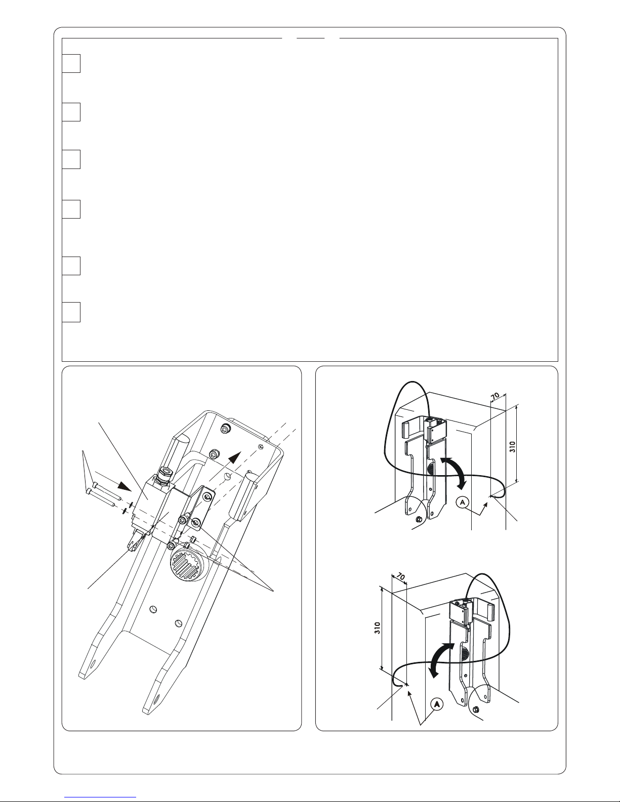
IMONTAGGIO DEL SENSORE : In caso di utilizzo del “kit sensore asta pivottante” rimuovere i particolari Ae Bdi Fig. 2. Fissare il micro
interruttore (rif. ) con le viti e le rondelle in dotazione (rif. ) alla staffa (rif. ). Assemblare la staffa alla tasca con le viti e le
rondelle in dotazione (rif. ). Praticare un foro di 10 mm. nella posizione A di Fig. 5, rispettando il senso di rotazione della sbarra,
per il passaggio del cavo precablato, utilizzando il passacavo fornito (rif. ). Collegare il contatto del micro interruttore in serie
al contatto di STOP della apparecchiatura.
SENSOR FIXING: If using the “sensor kit with pivoting rod”, remove parts A and Bin Fig. 2. Secure the microswitch (ref. ) with the
supplied screws and washers (ref. ) to the bracket (ref. ). Assemble the bracket to the pocket with the supplied screws and
washers (ref. ). Drill a 10 mm hole in position A of Fig. 5, to route the pre-wired cable, respecting the beam rotation direction, and
using the supplied cable gripper (ref. ). Connect the contact of the microswitch in series to the STOP Contact of the equipment.
GB
MONTAGE DU CAPTEUR : Si l’on utilise le “kit capteur lisse pivotante”, démonter les pièces Aet Bde la Fig. 2. Fixer le micro-inter-
rupteur (réf. ) avec les vis et les rondelles fournies (réf. ) à la patte (réf. ). Assembler la patte et la poche avec les vis et les
rondelles fournies (réf. ). Réaliser un trou de 10 mm dans la position A de la Fig. 5, en respectant le sens de rotation de la lisse,
pour le passage du câble pré-câblé, en utilisant le passe-câble fourni (réf. ). Connecter le contact du micro-interrupteur en
série au contact de STOP de l’appareillage.
F
MONTAGE DES SENSORS: Wenn der „Bausatz Drehstange” verwendet wird, die Teile A und Baus Abb. 2 entfernen. Den Mikroschalter
(Bez. ) mit den im Lieferumfang enthaltenen Schrauben und Scheiben (Bez. ) am Bügel (Bez. ) befestigen. Den Bügel mit
Hilfe der mitgelieferten Schrauben und Scheiben (Bez. ) mit dem Fach zusammenbauen. Unter Einhaltung der Drehrichtung des
Balkens eine Öffnung von 10 mm an der Position A aus Abb. 5 für den Durchgang des vorverdrahteten Kabels bohren und dabei
die mitgelieferte Kabelführung (Bez. ) verwenden. Den Kontakt des Mikroschalters in Reihenschaltung an den STOPP-Kontakt
des Geräts anschließen.
D
MONTAJE DEL SENSOR : En caso de utilización del «kit sensor barra pivotante» quite las piezas Ay Bde Fig. 2. Fije el microinterruptor
(ref. ) con los tornillos y las arandelas suministradas en dotación (ref. ) a la brida (ref. ). Ensamble la brida al bolsillo con los
tornillos y las arandelas suministradas en dotación (ref. ). Realice un taladrado de 10 mm. en la posición A de Fig. 5, respetando
el sentido de rotación de la barrera, para el paso del cable precableado, utilizando el pasacable suministrado (ref. ). Conecte
el contacto del microinterruptor en serie al contacto de STOP del equipo.
E
MONTAGE VAN DE SENSOR: Als het “bouwpakket sensor zwenkstang” wordt gebruikt, moeten de onderdelen Aen Bvan fig. 2
worden verwijderd. Bevestig de microschakelaar (ref. ) met de bijgeleverde schroeven en ringen (ref. ) aan de beugel (ref.
). Monteer de beugel aan de holte met de bijgeleverde schroeven en ringen (ref. ). Maak een gat van 10 mm in positie A
van fig. 5, volgens de draairichting van de slagboom, voor doorvoer van de voorbedrade kabel met behulp van de bijgele-
verde kabeldoorgang (ref. ). Schakel het contact van de microschakelaar in serie met het STOP-contact van de apparatuur.
NL

Other manuals for 620 STANDARD

6

This manual suits for next models

6

Other FAAC Other manuals

FAAC 620 SR Series User manual

FAAC

FAAC 620 SR Series User manual

FAAC 630 Series User manual

FAAC

FAAC 630 Series User manual

FAAC 615 User manual

FAAC

FAAC 615 User manual

FAAC 630 Series User manual

FAAC

FAAC 630 Series User manual

FAAC 620 STANDARD User manual

FAAC

FAAC 620 STANDARD User manual

FAAC 620 SR Series User manual

FAAC

FAAC 620 SR Series User manual

FAAC 620 SR Series User manual

FAAC

FAAC 620 SR Series User manual

Popular Other manuals by other brands

SealMaster SK300 owner's manual

SealMaster

SealMaster SK300 owner's manual

Nechville Warp Drive quick start guide

Nechville

Nechville Warp Drive quick start guide

YUNEEC E- GO manual

YUNEEC

YUNEEC E- GO manual

ATS Allison Transmission Pan kit installation manual

ATS

ATS Allison Transmission Pan kit installation manual

Siemens SIMATIC RF1000 Series operating instructions

Siemens

Siemens SIMATIC RF1000 Series operating instructions

Clarke CAR8MC user guide

Clarke

Clarke CAR8MC user guide

LevelOne WAB-7000 user manual

LevelOne

LevelOne WAB-7000 user manual

TESTO 320 basic instruction manual

TESTO

TESTO 320 basic instruction manual

Microlife FH 80 manual

Microlife

Microlife FH 80 manual

Parker Chelsea 540 Series owner's manual

Parker

Parker Chelsea 540 Series owner's manual

AKO AKO-575022 user manual

AKO

AKO AKO-575022 user manual

Apollo 16 Hardware manual

Apollo

Apollo 16 Hardware manual

Generic Ltl 8210A user manual

Generic

Generic Ltl 8210A user manual

Oceania Optimale Series Installation instruction

Oceania

Oceania Optimale Series Installation instruction

Soundstream PICASSO PCX2.180 owner's manual

Soundstream

Soundstream PICASSO PCX2.180 owner's manual

Ohlins VWS MI10 Mounting instruction

Ohlins

Ohlins VWS MI10 Mounting instruction

Ranch Hand HFF111BMT installation instructions

Ranch Hand

Ranch Hand HFF111BMT installation instructions

Duncan SH18 quick start guide

Duncan

Duncan SH18 quick start guide

manuals.online logo
manuals.online logoBrands
  • About & Mission
  • Contact us
  • Privacy Policy
  • Terms and Conditions

Copyright 2025 Manuals.Online. All Rights Reserved.