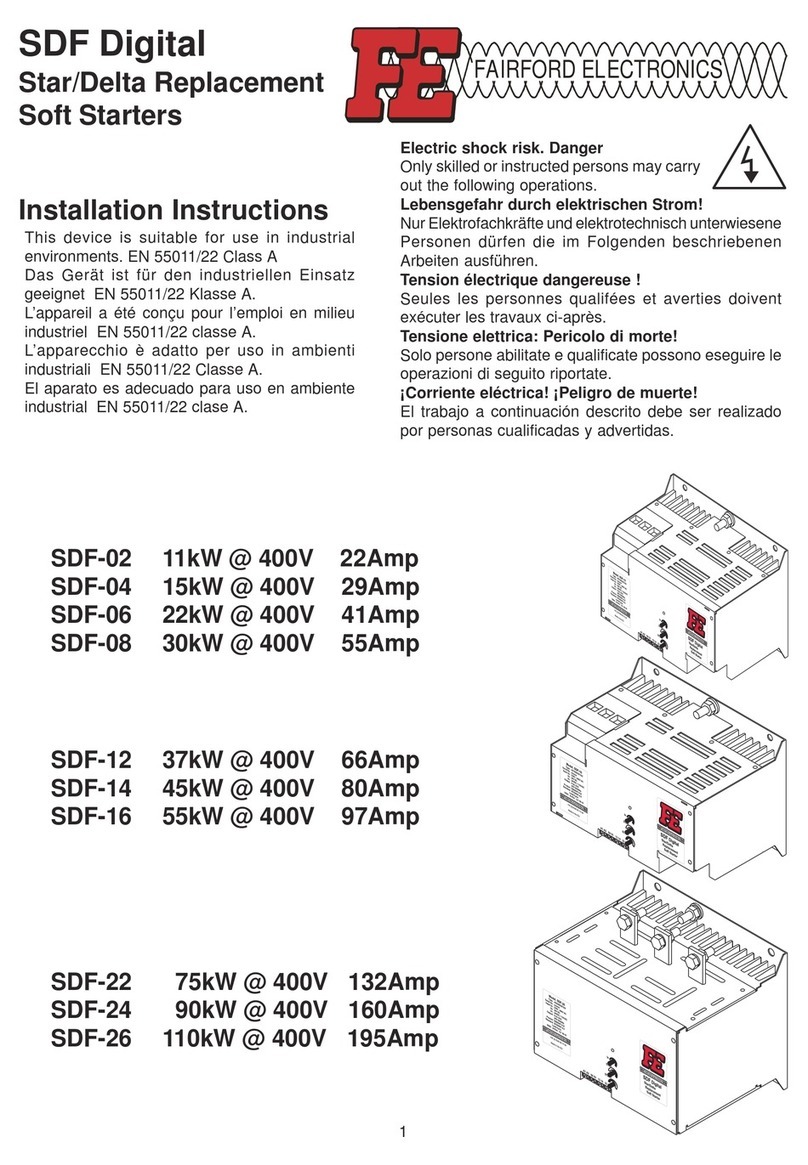
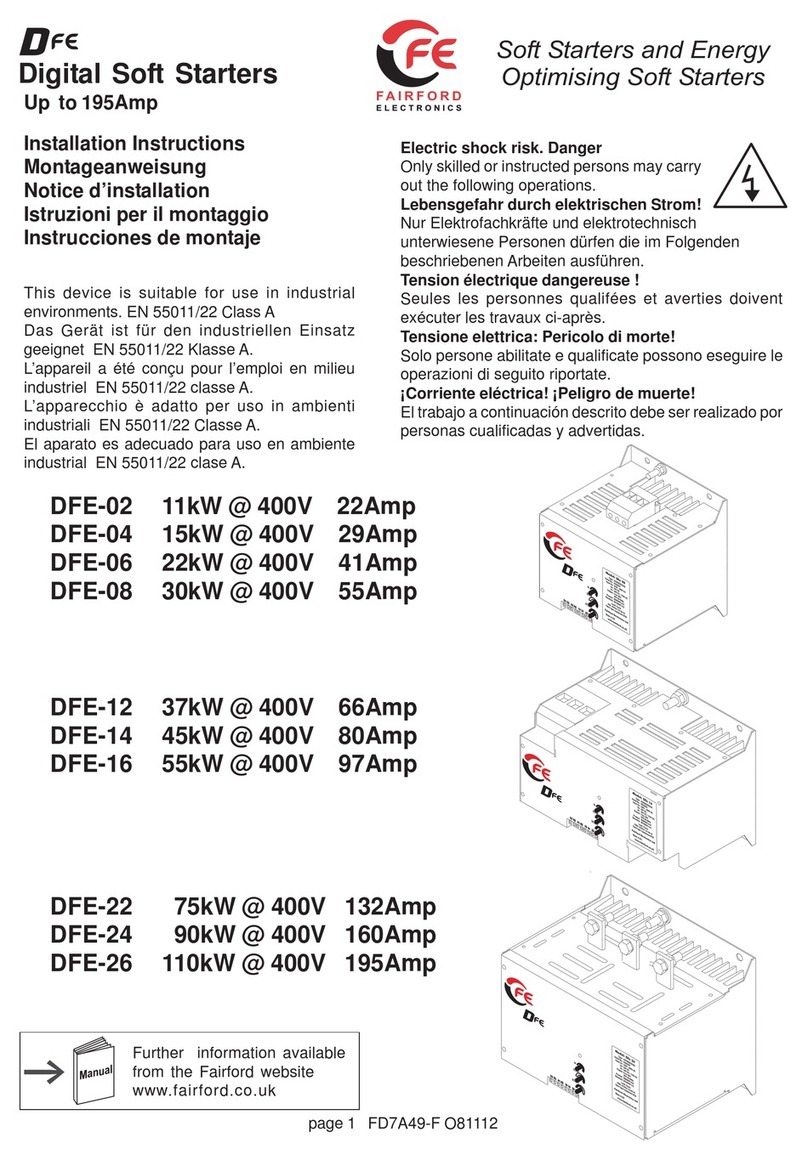
Fairford agility Series User manual

Innovation in soft starter technology
agilityTM
USER MANUAL
MAN-AGY-001. Version 04

1
agilityTM Series Soft Start User Manual
MAN-AGY-001. Version 04. 21/09/2018

2
agilityTM Series Soft Start User Manual
MAN-AGY-001. Version 04. 21/09/2018
agilityTM user manual
Fairford Electronics Ltd
Bristow House
Gillard Way, Ivybridge
PL21 9GG
UK
www.fairford.com
© 2018 by Fairford Electronics, all rights reserved
Copyright subsists in all Fairford Electronics deliverables including magnetic, optical and/or any
other soft copy of these deliverables. This document may not be reproduced, in full or in part,
without written permission. Enquiries about copyright of Fairford Electronics deliverables should
be made to Fairford Electronics Ltd. If, by permission of the copyright owner, any part of this
document is quoted, then a statement specifying the original document shall be added to the
quotation. Any such quotation shall be according to the original (text, figure or table) and may
not be shortened or modified.

3
agilityTM Series Soft Start User Manual
MAN-AGY-001. Version 04. 21/09/2018
Contents
Safety .................................................................................................................................. 7
Mechanical Installation .................................................................................................... 8
Mounting...................................................................................................................................... 8
Requirements for an Enclosure ................................................................................................. 8
Enclosure Ventilation.................................................................................................................. 8
Altitude Derate............................................................................................................................ 8
Dimensions .................................................................................................................................. 9
Horizontal Mounting................................................................................................................. 10
Mechanical Specification.......................................................................................................... 10
Electrical Installation ...................................................................................................... 11
Warnings .................................................................................................................................... 11
Electrical Supplies ..................................................................................................................... 11
General Specification................................................................................................................ 12
Short Circuit Protection............................................................................................................ 15
Electromagnetic Compatibility ................................................................................................ 16
Wire Sizes and Torques ............................................................................................................. 16
Motor Overload Protection ...................................................................................................... 17
Electrical Connections .............................................................................................................. 18
Main Circuit Wiring Diagram ................................................................................................... 18
Control Terminal Connection................................................................................................... 19
Control Terminal Functions ..................................................................................................... 19
Digital Input 2 (D2) Selectable Functions................................................................................ 19
Digital Output 21/22 Selectable Functions ............................................................................. 19
3-Wire Control Circuit Wiring Diagram ................................................................................... 20
2-Wire Control Wiring Diagram................................................................................................ 20
Configuration and Parameters...................................................................................... 21
Display and Controls ................................................................................................................. 21
Auto Setup Procedure (Auto App)............................................................................................ 22
Setup by Individual Parameter Settings (Advanced)............................................................. 22
Auto Application Setup Parameter Settings .......................................................................... 22
Operation Local Motor Start ...................................................................................................... 23
Auto Application Setup............................................................................................................. 23
Menu Structure................................................................................................................ 24
Function Descriptions..................................................................................................... 27

4
agilityTM Series Soft Start User Manual
MAN-AGY-001. Version 04. 21/09/2018
Trip and Fault Codes........................................................................................................ 36
Communication ............................................................................................................... 39
Modbus RTU Serial Communications ...................................................................................... 39
Modbus RTU Communications Interface ................................................................................ 39
Modbus RTU Connections......................................................................................................... 39
Modbus Communications Configuration
........................................................................... 40
Transmission Modes
................................................................................................................ 40
Message Structure For RTU Mode
...................................................................................... 40
Address
..................................................................................................................................... 40
Function Code
......................................................................................................................... 40
Data Field
.................................................................................................................................. 40
CRC .............................................................................................................................................. 41
Supported Functions
............................................................................................................. 41
Write Multiple Registers
....................................................................................................... 42
Memory Map.............................................................................................................................. 42
Message Timing ......................................................................................................................... 42
Modbus RTU Parameters................................................................................................ 43
Special Modbus Registers ......................................................................................................... 88
Modbus PNU Alphabetical Cross Reference ........................................................................... 94
Updating Firmware ......................................................................................................... 95
Update Procedure ..................................................................................................................... 95
Instruction for Updating........................................................................................................... 95
Applications...................................................................................................................... 97
Motor Suitability and Associated Considerations ................................................................. 97
Suitability ................................................................................................................................... 97
Induction Motor Characteristics.............................................................................................. 97
Rating.......................................................................................................................................... 97
Maximum Motor Cable Length ................................................................................................ 98
Power Factor Correction Capacitors ....................................................................................... 98
Lightly Loaded, Small Motors................................................................................................... 98
Motors Fitted with Integral Brakes ......................................................................................... 98
Older Motors.............................................................................................................................. 98
Wound-rotor or Slip-ring Motors ............................................................................................. 98
Enclosures .................................................................................................................................. 98
EU Compliance with the EMC Directive................................................................................... 99

5
agilityTM Series Soft Start User Manual
MAN-AGY-001. Version 04. 21/09/2018
Fuses ........................................................................................................................................... 99
Rules for Specific Applications................................................................................................. 99
High Inertia Loads ..................................................................................................................... 99
Frequent Starting ...................................................................................................................... 99
Soft-Stopping ............................................................................................................................. 99
Reversing Configuration........................................................................................................... 99
Replacement of Fluid Couplings ............................................................................................ 100
Two-speed Motor Applications .............................................................................................. 100
Overhauling Loads .................................................................................................................. 100
Application Table..................................................................................................................... 100
Concepts and principles of fixed-speed induction motor starting and control. .............. 102
Introduction............................................................................................................................. 102
The Induction Motor ............................................................................................................... 102
Starting Induction Motors...................................................................................................... 105
Electro-Mechanical Methods Of Starting.............................................................................. 105
The Semiconductor Motor Controller ................................................................................... 107
Running Induction Motors ..................................................................................................... 108
Reliability Considerations ...................................................................................................... 109
EMC.................................................................................................................................. 111
Electromagnetic Compatibility (EMC) ................................................................................... 111
Introduction............................................................................................................................. 111
Applicable Standard Within the EU
.................................................................................... 111
Mandatory Requirements Within the EU ............................................................................. 111
Guidance for Installation Personnel and System Designers .............................................. 111
EMC Basic Criteria ................................................................................................................... 112
Purchasing Implications of Meeting an EMC Standard
................................................. 112
Basic EMC Considerations ...................................................................................................... 112
Immunity.................................................................................................................................. 112
Emissions
................................................................................................................................. 112
Emissions - Harmonics
.......................................................................................................... 112
Emissions - Radio Frequency (RF)
........................................................................................ 113
Emissions - Conducted
.......................................................................................................... 113
Important SystemsInformation
........................................................................................ 113
Strategies for Attaining and Maintaining EMC Compliance
......................................... 114
Accessories ..................................................................................................................... 115

6
agilityTM Series Soft Start User Manual
MAN-AGY-001. Version 04. 21/09/2018
Power Supply (AGY-020).......................................................................................................... 115
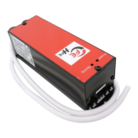
Connections ............................................................................................................................. 116
Control Terminal ..................................................................................................................... 116
Functions.................................................................................................................................. 116
3-Wire Control Using AGY-020 ................................................................................................ 117
2-Wire Control Using AGY-020 ................................................................................................ 117
Fan (AGY-030) ........................................................................................................................... 118
Remote Keypad (AGY-010) ...................................................................................................... 119
Network Connection............................................................................................................... 119
Keypad Connection and Operation
....................................................................... 120
Operation ................................................................................................................................. 120
Initial Power-Up....................................................................................................................... 120
Selecting Units To Monitor/Configure................................................................................... 121
Keypad Installation ....................................................................................................... 123
Mounting.................................................................................................................................. 123
Sizing Guide .................................................................................................................... 124
Key to Part Numbers............................................................................................................... 125
Notes............................................................................................................................... 125

7
agilityTM Series Soft Start User Manual
MAN-AGY-001. Version 04. 21/09/2018
Important information
Installers should read and understand the instructions in this guide prior to installing, operating
and maintaining the soft starter. The following symbols may appear in this guide or on the soft
starter to warn of potential hazards or to draw attention to certain information.
Dangerous Voltage
Indicates the presence of a hazardous voltage which could result in personal injury or death.
Warning/Caution
Indicates a potential hazard. Any instructions that follow this symbol should be obeyed to avoid
possible damage to the equipment, and personal injury or death.
Protective Earth (Ground)
Indicates a terminal which is intended for connection to an external conductor for protection
against electric shock in case of a fault.
Caution Statements
The examples and diagrams in this manual are included solely for illustrative purposes. The
information contained in this manual is subject to change at any time and without prior notice.
In no event will responsibility or liability be accepted for direct, indirect or consequential
damages resulting from the use or application of this equipment.
• agilityTM soft starters contain dangerous
voltages when connected to the mains
supply. Only qualified personnel that have
been completely trained and authorised,
should carry out installation, operation and
maintenance of this equipment.
• Installation of the soft starter must be made
in accordance with existing local and national
electrical codes and regulations and have a
minimum protection rating.
• It is the responsibility of the installer to
provide suitable grounding and branch circuit
protection in accordance with local electrical
safety codes.
• This soft starter contains no serviceable or
re-usable parts.
Safety

8
agilityTM Series Soft Start User Manual
MAN-AGY-001. Version 04. 21/09/2018
Mounting
Fix the unit to a flat, vertical surface using the mounting holes (or slots) on its base-plate. The
mechanical outline diagrams, shown on Page 8, give the dimensions and mounting hole
positions for each model. Ensure that:
•The orientation of the unit has the ‘TOP’ uppermost (unless horizontally mounted –
see page 9).
•The location allows adequate front access.
•The screen can be viewed.
Do not install other equipment that generates significant heat close to the soft starter.
Requirements for an Enclosure
For a typical industrial environment, an enclosure would provide the following:
•A single location for the unit and its protection/isolation switch-gear.
•The safe termination of cabling and/or bus-bars.
•Means to effect proper air flow through the enclosure.
Enclosure Ventilation
When fitting agility
TM
into a cabinet, ventilation must be provided. The heat dissipated can be
approximated with the formula: -
Starting
Watts (agility
TM
) = start current(A) x start time(s) x number of starts per hour/ 1800
Running
Watts(agility
TM
) = 0.4 x running amps
Use the following formula to determine the fan requirement. An allowance has been incorporated into
the formula so that the figure for Q is the air delivery in the fan supplier’s data.
Q = (4 x Wt/ (Tmax-Tamb))
Q = volume of air (cubic metres per hour-m3/h)
Wt = Heat produced by the unit and all other heat sources within the enclosure (Watts) Tmax =
Maximum permissible temperature within the enclosure (40°C for a fully rated agility™)
Tamb = Temperature of the air entering the enclosure (°C) [to work in CFM, substitute °F for °C. Q is now
in CFM]
Altitude Derate
Altitude above sea level 1000m (3281ft). Above 1000m de rate by 1% of agility™ Ie per 100m
(328ft) to a maximum altitude of 2000m (6562ft)
Ambient Temperature Derate
-20°C (-4°F) to 40°C (104°F). Above 40°C de-rate linearly by 2% of agility™ Ie per °C to a maximum
of 60°C (140°F).
MechanicalInstallation

9
agilityTM Series Soft Start User Manual
MAN-AGY-001. Version 04. 21/09/2018
Dimensions
AGY-101 to AGY-113
[ ] = inch
Weight 1.97kg (3.75lb)
Fitting
Air Flow
Mechanical Installation (continued)
25mm [0.98]
25mm [0.98]
75mm [2.95]
75mm [2.95]
25mm [0.98]

10
agilityTM Series Soft Start User Manual
MAN-AGY-001. Version 04. 21/09/2018
Horizontal Mounting
The agilityTM unit may be mounted horizontally if required. It will be necessary to apply a deration to the
unit power in this instance –see Horizontal Rating Table (Page 13)
Mechanical Specification
Mechanical Specifications
Model (AGY-)
101
103
105
107
109
111
113
Frame Size
1
Heat output (W)
9
12
14
16
20
25
30
Weight kg [lb]
1.97 [4.20]
Ambient Operating Temp.
-20°C [-4°F] to 40°C [104°F] ; above 40°C
derate linearly by 2% of agility
TM
Ie per °C to
a maximum of 60°C (140°F)
Transportation and Storage
Temperature
-20°C to 60°C [-4°F to 140°F] continuous
Humidity
max 85% non-condensing, not exceeding
50% @ 40°C [104°F]
Maximum Altitude
1,000m [3281ft] ; above 1000m derate by 1%
of agility
TM
I
e
per 100m (328ft) to a maximum
altitude of 2,000m (6562ft)
Environmental Rating
Main Circuit: IP00 (IP20 with optional finger
guards); Control Circuit: IP20; No corrosive
gases permitted
Mechanical Installation (continued)

11
agilityTM Series Soft Start User Manual
MAN-AGY-001. Version 04. 21/09/2018
Warnings
Isolation
Caution: agility
TM
uses semiconductor devices in the main circuit and is not designed to
provide isolation. For this reason isolation means must be installed in the supply circuit in
accordance with the appropriate wiring and safety regulations
Electrical Control Supply Requirements
All electrical connections are made to power input and output terminals, control terminals
and an earth stud.
Fuse Protection
The Mains Supply and the Control Supply each require protection. Although all units have
electronic overload protection for the Soft Starter, the installer should always fit fuses, for
motor protection, between the unit and the Mains Supply, not between the unit and the motor.
Semiconductor fuses can be supplied as an option for short-circuit protection of the
semiconductors. These fuses must be fitted externally to the agility
TM
chassis to comply with
certain standards. It is the responsibility of the installer and system designer/specifier to ensure
that the required standards or regulations are not affected by so doing.
Safety
agility
TM
soft starters contain hazardous voltages when connected to the electrical power
supply. Only qualified personnel who are trained and authorized should carry out
installation, operation and maintenance of this equipment. Refer to and carefully follow all
of the ‘Warnings’ section at the beginning of this user manual, as well as other warnings and notes
throughout the manual.
Electrical Supplies
The unit requires a 3-phase balanced Mains Supply to provide the power for the controlled motor,
and a 24Vdc for the internal control circuitry. The unit will not operate unless the control supply
voltage is within the specified limits.
ElectricalInstallation

12
agilityTM Series Soft Start User Manual
MAN-AGY-001. Version 04. 21/09/2018
General Specification
Product Standard
EN 60947-4-2: 2012
Rated operational voltages
Ue
200Vac to 600Vac (See Key to part numbers)
Rated operational current
Ie
See Rating Table
Rating index
See Rating Table
Rated frequency/frequencies
50 - 60Hz ± 5Hz
Rated duty
Uninterrupted.
Form designation
Form 1, Internally Bypassed
Method of operation
Symmetrically controlled starter
Method of control
Semi-automatic
Method of connecting
Thyristors connected between windings and supply
Number of poles
3 main poles, 2 main poles controlled by
semiconductor switching element
Rated insulation voltage
Ui
Main circuit
See Key to
part
numbers
Control supply circuit
24Vdc
Rated impulse withstand voltage
Uimp
Main circuit
6 kV
Control supply circuit
4 kV
IP code
Main circuit
IP00 (IP20
optional)
Supply and Control circuit
IP20
Overvoltage Category / Pollution
degree
III / 3
Rated conditional short-circuit current and
type of co-ordination with associated short
circuit protective device (SCPD)
Type 1 co-ordination
See Short Circuit Protection Tables for
rated conditional short-circuit current
and required current rating and
characteristics of the associated SCPD
Electrical Installation (continued)

13
agilityTM Series Soft Start User Manual
MAN-AGY-001. Version 04. 21/09/2018
General Specification (continued)
As
Control
Supply input
0, 24V
Standard
supply
Kind of current, rated
frequency
d.c.
Rated voltage Us
24Vd.c.
Maximum power consumption
12VA
Control
Programmable opto-isolated
inputs
D1, D2
circuit
Common input, marking
COM
Kind of current, rated
frequency
d.c.
Rated voltage Uc
24Vd.c.
Protect with
4A
With
Control
Supply input
L, N
UL listed
fuse
extra
Supply
Kind of current, rated
frequency
a.c., 50 - 60Hz ± 5Hz
module
Rated voltage Us
110V to 230V a.c.
Rated input current
1A
Control
Programmable opto-isolated
inputs
D1, D2
circuit
Common input
COM
Kind of current, rated
frequency
a.c., 50 - 60Hz ± 5Hz
Rated voltage Uc
110V to 230V a.c.
Auxiliary
Form A –Single gap make -contact (normally
open)
13, 14
circuit 1)
Form B –Single gap break-contact (normally
closed)
21, 22
Utilization category, voltage rating, current
rating
Resistive load,
250Vac, 2A.
Cosø =0.5, 250Vac,
2A.
Electronic
Trip Class
10 (factory default), 20 or 30
(selectable)
overload relay
Current setting
7A to Ie
with manual reset and
thermal
Rated frequency
50 to 60Hz ± 5Hz
memory
Time-current characteristics
See ‘Motor Overload ‘cold’ trip curves’
1)
Compliant with Annex S of IEC 60947-1:2007 at 24Vd.c.
Electrical Installation (continued)

14
agilityTM Series Soft Start User Manual
MAN-AGY-001. Version 04. 21/09/2018
Rating Table –Vertical Mounting
Ie
kW 1)
FLA
Hp 2)
Trip Class 10
Trip Class
20
Trip Class 30
A 3)
230V
400V
500V 4)
A 3)
200V
208V
220-240V
440-480V
550-600V 4)
Ie: AC-53a:
3.5-17: 90-5 5)
Ie: AC-53a:
4-19: 90-5 5)
Ie: AC-53a:
4-29: 90-5 5)
17
4
7.5
7.5
17
3
5
5
10
15
-
-
AGY-101
17
4
7.5
7.5
17
3
5
5
10
15
-
AGY-101
AGY-103
17
4
7.5
7.5
17
3
5
5
10
15
AGY-101
AGY-103
AGY-105
22
5.5
11
11
22
5
5
7.5
15
20
AGY-103
AGY-105
AGY-107
29
7.5
15
15
27
7.5
7.5
7.5
20
25
AGY-105
AGY-107
AGY-109
35
7.5
18.5
22
34
10
10
10
25
30
AGY-107
AGY-109
AGY-111
41
11
22
22
41
10
10
10
30
40
AGY-109
AGY-111
AGY-113
55
15
30
37
52
15
15
15
40
50
AGY-111
AGY-113
-
66
18.5
37
45
65
20
20
20
50
60
AGY-113
-
-
Rating Table –Horizontal Mounting
Ie
kW 1)
FLA
Hp 2)
Trip Class 10
Trip Class
20
Trip Class 30
A 3)
230V
400V
500V 4)
A 3)
200V
208V
220-240V
440-480V
550-600V 4)
Ie: AC-53a:
3.5-17: 90-5 5)
Ie: AC-53a:
4-19: 90-5 5)
Ie: AC-53a:
4-29: 90-5 5)
17
4
7.5
7.5
17
3
5
5
10
15
-
AGY-101
AGY-103
17
4
7.5
7.5
17
3
5
5
10
15
AGY-101
AGY-103
AGY-105
17
4
7.5
7.5
17
3
5
5
10
15
AGY-103
AGY-105
AGY-107
22
5.5
11
11
22
5
5
7.5
15
20
AGY-105
AGY-107
AGY-109
29
7.5
15
15
27
7.5
7.5
7.5
20
25
AGY-107
AGY-109
AGY-111
35
7.5
18.5
22
34
10
10
10
25
30
AGY-109
AGY-111
AGY-113
41
11
22
22
41
10
10
10
30
40
AGY-111
AGY-113
55
15
30
37
52
15
15
15
40
50
AGY-113
-
Minimum current ratings based on typical rated operation currents of motors for the
corresponding rated operational powers.
Current rating optimised for kW@400V & hp@440-480V - Ref IEC 60947-4-1:2009 Table G.1 where
applicable.
1) Rated operational powers in kW as per IEC 60072-1 (primary series) corresponding to IEC current
rating.
2) Rated operational powers in HP as per UL508 corresponding to FLA current rating.
3) The Ieand FLA rating applies for a maximum surrounding air temperature of 40oC. Above 40oC de-rate
linearly by 2% of Ie or FLA per oC to a maximum of 60oC.
4) kW and HP ratings applicable for AGY-101-6 to AGY-113-6 models only.
5) A duty cycle F-S of up to 90-40 (up to 40 starts per hour) is possible with optional fan fitted
Electrical Installation (continued)

15
agilityTM Series Soft Start User Manual
MAN-AGY-001. Version 04. 21/09/2018
Short Circuit Protection
Type designation (AGY-)
101-6
103-6
105-6
107-6
109-6
111-6
113-6
Rated operational current
Ie
A
17
22
29
35
41
55
66
Rated conditional short circuit
current
Iq
kA
5
5
5
5
5
5
10
Class J time-delay fuse #1
Maximum
rating Z1
A
30
40
50
60
70
100
125
UL Listed inverse-time delay circuit
breaker #1
Maximum
rating Z2
A
60
60
60
60
60
150
150
Semiconductor fuse (class aR) #2,
duty ≤5 starts per hour.
Type
Mersen 6,9 URD 30 _
Bussmann 170M30__
Bussmann 170M31__
Bussmann 170M32__
SIBA 20 61___
Fuse rating
A
100A
100A
160A
160A
160A
200A
200A
Semiconductor fuse(class aR), #2 duty
>5 starts per hour #3.
Type
Mersen 6,9 URD 30 _
Mersen 6,9 URD 31 _
Bussmann 170M30__
Bussmann 170M40__
Bussmann 170M31__
Bussmann 170M41__
Bussmann 170M32__
Bussmann 170M42__
SIBA 20 61___
SIBA 20 61___
Fuse rating
A
160A
160A
200A
200A
250A
250A
250A
# 1. Suitable For Use On A Circuit Capable Of Delivering Not More Than ___Iq___ rms Symmetrical Amperes,
600Volts Maximum, When Protected by Class J time delay Fuses with a Maximum Rating of ___Z1___ or
by a Circuit Breaker with a Maximum Rating of ___Z2___.
# 2. Correctly selected semiconductor fuses can provide additional protection against damage to the
agilityTM unit (This is sometimes referred to as type 2 co-ordination). These semiconductor fuses are
recommended to provide this increased protection.
# 3. Only when optional fan is fitted, see Rating table (Note 5).
Electrical Installation (continued)

16
agilityTM Series Soft Start User Manual
MAN-AGY-001. Version 04. 21/09/2018
Electromagnetic Compatibility
EMC Emission levels
EN 55011
Class A
EMC Immunity levels
IEC 61000-4-2
8kV/air discharge or 4kV/contact discharge
IEC 61000-4-3
10 V/m
IEC 61000-4-4
2kV/5kHz (main and power ports)
1kV/5kHz (signal ports)
IEC 61000-4-5
2kV line-to-ground
1kV line-to-line
IEC 61000-4-6
10V
NOTICE: This product has been designed for environment A. Use of this product in environment
B may cause unwanted electromagnetic disturbances, in which case the user may be required to
take adequate mitigation measures
Wire Sizes and Torques
Terminal
Wire Size
Torque
mm2
AWG
Nm
Ib-in
Main terminals Cu STR 75oC only
2.5 - 70
12- 2/0
9
80
Control terminals
0.5–1.5
20-16
0.8
7.0
M6 screw
Protective
Earth 1) Cu
only
≥ 10
≥ 8
8
70
1) Protective Earth wire size based on bonding conductor requirements of UL508 Table 6.4 and UL508A
Table 15.1.
Electrical Installation (continued)

17
agilityTM Series Soft Start User Manual
MAN-AGY-001. Version 04. 21/09/2018
Motor Overload Protection
agility
TM
provides full motor overload protection, configurable through the user interface.
Overload trip settings are determined by the Motor Current setting and the Trip Class setting. Trip
class choices are Class 10, Class 20, and Class 30. The agility
TM
soft starters are protected using
full I
2
T motor overload with memory. See Appendix 1 for sizing guide.
Please note: When the overload has tripped, there is a forced cooling time to allow the
overload to recover before the next start.
The ‘warm’ trip times are 50% of the ‘cold’ trip time
Electrical Installation (continued)

18
agilityTM Series Soft Start User Manual
MAN-AGY-001. Version 04. 21/09/2018
Electrical Connections
Main Circuit Wiring Diagram
Electrical Installation (continued)
3-Phase Electrical
Supply
Connections
(L1, L2, L3)
RJ45
connector
(Modbus RTU)
USB
Connector
Control
Terminals
AC Induction Motor
Connections
(T1, T2, T3)

19
agilityTM Series Soft Start User Manual
MAN-AGY-001. Version 04. 21/09/2018
Control Terminal Connection
Control Terminal Functions
#1 24V dc Specification: 24V 10VA, residual ripple < 100Mv, spikes/switching peaks < 240mv,
#2 The voltage applied to the digital inputs D1 and D2 must not exceed 24V dc
#3 230Vac, 1A, AC15. 30Vdc, 0.5A resistive
Digital Input 2 (D2) Selectable Functions
Different functions may be assigned to Digital Input 2 in the I/O menu. Available assignments are:
Reset
Hold Start Ramp
Enable
Fire Mode (In Fire Mode all trips are disabled)
Digital Output 21/22 Selectable Functions
The output may be mapped to Fault or Top-of-Ramp indication
Terminal
Description
Function
Selectable
Note
24Vdc
Control Supply +Us
No
#1
0V
Control Supply -Us
No
COM
Digital Inputs Common
No
D1
Digital Input 1
No
#2
D2
Digital Input 2
Yes
#2
13/14
Main Contactor Control (Run
Relay)
No
#3
21/22
Fault Relay
Yes
#3
24V
COM
0V
13
D1
14
D2
22
21
Electrical Installation (continued)
Other manuals for agility Series
1
This manual suits for next models
7
Table of contents
Other Fairford Controllers manuals

Fairford
Fairford synergy User manual

Fairford
Fairford iERS HFE-1 User manual

Fairford
Fairford Synergy SGY-401 User manual

Fairford
Fairford SDF-02 User manual

Fairford
Fairford Dfe series User manual

Fairford
Fairford Dfe series User manual

Fairford
Fairford Synergy SGY-101 User manual

Fairford
Fairford XFE Series Owner's manual

Fairford
Fairford HFE-2 User manual

Fairford
Fairford HFE-30 User guide