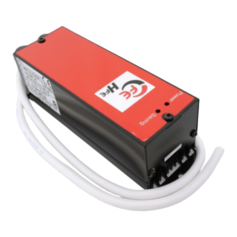
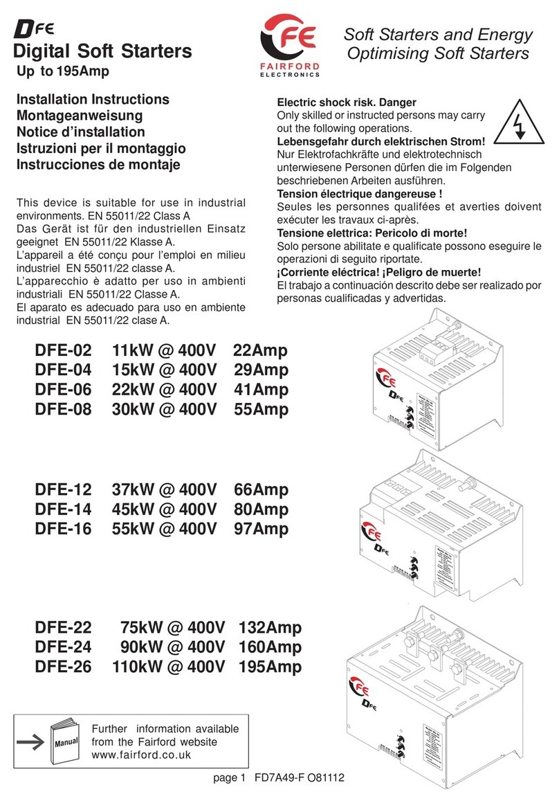
Fairford SDF-02 User manual

1
SDF Digital
Star/Delta Replacement
Soft Starters
FAIRFORD ELECTRONICS
SDF-02 11kW @ 400V 22Amp
SDF-04 15kW @ 400V 29Amp
SDF-06 22kW @ 400V 41Amp
SDF-08 30kW @ 400V 55Amp
SDF-12 37kW @ 400V 66Amp
SDF-14 45kW @ 400V 80Amp
SDF-16 55kW @ 400V 97Amp
SDF-22 75kW @ 400V 132Amp
SDF-24 90kW @ 400V 160Amp
SDF-26 110kW @ 400V 195Amp
Installation Instructions
This device is suitable for use in industrial
environments. EN 55011/22 Class A
Das Gerät ist für den industriellen Einsatz
geeignet EN 55011/22 Klasse A.
L’appareil a été conçu pour l’emploi en milieu
industriel EN 55011/22 classe A.
L’apparecchio è adatto per uso in ambienti
industriali EN 55011/22 Classe A.
El aparato es adecuado para uso en ambiente
industrial EN 55011/22 clase A.
Electric shock risk. Danger
Only skilled or instructed persons may carry
out the following operations.
Lebensgefahr durch elektrischen Strom!
NurElektrofachkräfteundelektrotechnischunterwiesene
Personen dürfen die im Folgenden beschriebenen
Arbeiten ausführen.
Tension électrique dangereuse !
Seules les personnes qualifées et averties doivent
exécuter les travaux ci-après.
Tensione elettrica: Pericolo di morte!
Solo persone abilitate e qualificate possono eseguire le
operazioni di seguito riportate.
¡Corriente eléctrica! ¡Peligro de muerte!
El trabajo a continuación descrito debe ser realizado
por personas cualificadas y advertidas.

2
SDF-12 to SDF-16 37kW to 55kW
140
125
135
60 90
Ø7
135
76
135 203
160
125
140
Ø7
SDF-02 to SDF-06 11kW to 30kW
Mountings suitable for M6.
1L1, 3L2, 5L3,
2T1, 4T2, 6T3
mm
2
AWG mm Nm mm
16 4 13 2.0 0.8 x 4
1L1, 3L2, 5L3,
2T1, 4T2, 6T3
mm
2
AWG mm Nm mm
35 1 17 3.0 1.2 x 6.5
Mountings suitable for M6.
160mm x 125mm centres
M6 8 Nm
M6 8 Nm
Dimensions – Abmessungen – Dimensioni – Dimensiones
Power cables/Leistungsleitungen/Conducteurs
de puissance/Cavi di potenza/Conductores de
potencia
Power cables/Leistungsleitungen/Conducteurs
de puissance/Cavi di potenza/Conductores de
potencia

3
SDF-22 to SDF-26 75kW to 110kW
76
160 203
160
48 48
165
170
190
145
Ø 8.5
1L1, 3L2, 5L3, 2T1, 4T2, 6T3
95mm 4/0 AWG 20mm x 5mm M8 - 12Nm
2
PE
M8 12 Nm
Mountings suitable for M6.
160mm x 145mm centres
Dimensions – Abmessungen – Dimensioni – Dimensiones
A1, A2 S0, S1
13, 14 23, 24
mm AWG mmNmmm
2
1 x 0.75 – 2.5 18 – 12 6 0.8 0.5 x 3.5
2 x 0.75 - 1 18 – 16 11 0.8 0.5 x 3.5
A1 A2 S0 S1 13 14 23 24
Control
supply
24VDC
+-
Start/stop
24VDC/110VAC
3 Amp NO
AC11 230VAC
Control cables –Steuerleitungen – Conducteurs de commande –
Cavi comandi - Conductores de mando
Power cables/Leistungsleitungen/Conducteurs
de puissance/Cavi di potenza/Conductores de
potencia

4
Standard connection – Standardanschluss – Raccordement standard –
Collegamento standard – Conexión estándar
13
K1.1
14
S2
S1
K1M
Z1
S0
SDF
S1
13
SDF
14
+ 24VDC
0 VDC
A1
SDF
A2
+24VDC
or 110VAC
0VDC or N
3 wire control 24 VDC/110VAC
Soft starter with mains contactor - Softstarter mit Netzschütz – Démarreur progressif avec contacteur réseau
– Softstarter con contattore di rete – Arrancador suave con contactor red
Where several conductors are to be connected, the difference between the wires/cables
used must not exceed one DIN Standard size level.
Bei Mehrleiteranschluss darf maximal ein DIN-Normgrößen-Sprung zwischen den
verwendetenLeiternliegen.
En cas de raccordement de plusieurs conducteurs, il faut 1 écartement normalisé max.
entre les conducteurs.
In caso di collegamento a più conduttori, è ammesso al massimo un salto di grandezze
DIN standard fra i conduttori utilizzati.
En caso de conexión de múltiples conductores puede haber como máximo un salto de
magnitud normalizada DIN entre los conductores utilizados.
M
3~
U1
V1 V2
W2
W1
U2
SDF
2T1
6T3
4T2
M
3~
U1
V1 V2
W2
W1
U2
SDF
2T1
6T3
4T2
Make the Delta
at the motor Make the Delta
at the SDF
F1
K1M
M
3~
2T1
6T3
4T2
M1
SDF
Z1
L1
L2
L3
PE
1L1
5L3
3L2
23 24
ready
/fault
13 14
run
A1
+A2
-S0 S1
PFC
start/stop
<100m
24VDC

5
+24VDC
or 110VAC
0VDC or N
SDF
S1
Z1
S0
01
S1
+ 24VDC
0 VDC
A1
SDF
A2
2 wire control element
24 Volt within cabinet, 110 Volt external
F1
Q1
M
3~
2T1
6T3
4T2
M1
SDF
Z1
L1
L2
L3
PE
I I I
1L1
5L3
3L2
23 24
ready
/fault
13 14
run
A1
+A2
-S0 S1
PFC
start/stop
<100m
24VDC
Halbleiterschütz – Semiconductor contactor – Contacteur à semi-conducteurs –
Contattore a semiconduttori – Contactor semiconductor
Q1 = Cable protection - Leitungsschutz - Protezione di linea -
Protección de cable - Protection de câbles
K1M = Main contactor - Netzschütz - Contattore di rete - Contactor red -
Contacteur réseau
Z1 = Overload relay - Überlastrelais - Relè termico - Relé de sobrecarga -
Relais thermique
F1 = Semiconductor fuse for type 2 coordination, in addition to Q1 -
Halbleitersicherung für Zuordnungsart 2, zusätzlich zu Q1 -
Per avere la protezione del semiconduttore in coordinamento di tipo 2, è
necessario un fusibile in aggiunta a Q1 -
Fusible semiconductor para tipo de coordinación 2, adicionalmente a Q1 -
Fusible pour semi-conducteurs pour coordination de type 2, additionnel à Q1
SDF = Soft Starter - Halbleiterschütz -Contactor semiconductor - Contattore a
semiconduttori - Contacteur à semi-conducteurs
S1-S2 = Start/Stop - Start/Stopp - Start/Stop - Arranque/Parada -
Démarrage/Arrêt
= EMERGENCY-STOP - NOT-AUS - ARRESTO D’EMERGENZA -
PARADA DE EMERGENCIA - ARRET D’URGENCE
SERVICING
WARNING NEVER CARRY OUT ANY WORK ON ELECTRICAL OR
MECHANICAL EQUIPMENT BEFORE ISOLATING ALL POWER
SUPPLIES.THE SDF DOES NOT PROVIDE ISOLATION.
LIVE OUTPUTS MAY BE PRESENT WITHOUT MOTOR ROTATION

6
U
L1, L2, L3
S0, S1
U
T1, T2, T3
Flash
green
A1, A2
1 flash
ready 2 flash
starting 3 flash
run 4 flash
stopping 1 flash
ready
~½ second
with circuit breaker with contactor
Flash Green
1 ready
2 starting
3 run
4 stopping
Flash Red (fault)
1 SCR / supply
2 thermal
3 Uc <24V
Settings - Einstellungen - Réglages - Regulazioni - Regulaciones
Start
Stop
Ie
70%
100%
12
0.5
12
0
Motor current:- 100% for standard rating
70% for smaller motors
Soft Stop time:- 0 = default
range 0 S to 12 S
Soft Start time:- ~5 = default
range 0.5 S to 12S
☺
LED green - LED grün – DEL vert –
LED verde - LED verde
1 Ready for operation – Betriebsbereit –
Prêt à fonctionner –Pronto al funzionamento –
En condiciones para funcionamiento
2 Starting – in Rampe – en rampe – in rampa –
en rampa
3 Top of ramp – Rampenende erreicht –
Fin de rampe atteinte –Fine rampa – Fin de rampa
4 Soft-Stop – Soft stop – Arrêt progressif – Soft-Stop –
Paro suave
#Fault LED red – Fehler LED rot – DEL erreur
rouge – LED errore rosso –LED error rojo
1 SCR or supply
2 Too hot
3 Control supply low volts

7
EMC EMISSION AND IMMUNITYLEVELS
ESD immunity EC 61000-4-2 4kV contact.
8kV air discharge
R F immunity EC 61000-4-6 140dBuV over 0.15-80MHz
R F immunity EC 61000-4-3 10V/m over 80 -1000MHz
Fast Transient immunity EC 61000-4-4 2kV/5kHz
Surge immunity EC 61000-4-5 2kV line to ground
1kV line to line
Conducted RF emissions EN 55011 Class A
Radiated RF emissions EN 55011 Class A
Rated Impulse withstand Voltage (Uimp) 2.5kV
Rated Insulation Voltage (Ui) 500V
Pollution Degree 2
Rated Short Circuit Current (Iq)* 10kA
Short Circuit Co-ordination* Type 2
Ambient Temperature 0°C to 40°C.
Above 40°C de-rate linearly by 2% of unit FLC per °C to a derate of 40% at 60°C
Transport and Storage -25°C to +60°C
Altitude 1000m. Above 1000m de-rate linearly by 1% of unit FLC per 100m to a
max. altitude of 2000m.
Humidity max. 85% non-condensing, not exceeding 50% at 40°C
IP Rating IP20 or IP00
DesignStandards
IEC 60947-4-2;
EN60947-4-2
“AC Semiconductor Motor
ControllersandStarters”
* When protected by
recommended
semiconductor fuse.
Attention!
Within the scope of the EU Directives, the SDF soft starters and their accessories may be
commissioned only provided it is established that the machine fulfils the protective
requirements of Machine Directive 89/392/EWG.
Achtung!
Im Geltungsbereich der EG-Richtlinien dürfen die Softstarter der Reihe DS4 und deren
ZubehörnurdanninBetriebgenommenwerden,wennfestgestelltwird,dassdieMaschine
die Schutzanforderungen der Maschinenrichtlinie 89/392/EWG erfüllt.
¡Atención!
En el campo de aplicación de la normativa CE, los arrancadores suaves de la serie SDF
y sus correspondientes accesorios sólo deberán ponerse en marcha cuando se asegure
quelamáquina cumple con las exigenciasdeseguridadde la normativa de máquinas89/
392/CE.
Attention !
Enapplicationdes directives européennes, lesdémarreursprogressifs de la gammeSDF
et leurs accessoires ne doivent être mis en service que s’il a été vérifié que la machine
répond bien aux exigences de la directive machines 89/392/EWG.
Attenzione!
Nel campo di validità delle direttive CEE i softstarter della serie SDF e i loro accessori
possono essere messi in esercizio solamente se è verificato che la macchina soddisfai
requisiti di sicurezza delle direttive macchine 89/392/CEE.

8
Copyright ©2005 Fairford Electronics Ltd.
Document No. FD7A49 IssueB 050407 M-7A49-FE
FAIRFORD ELECTRONICS LIMITED
Derby Road,
Kingsbridge,
Devon, TQ7 1JL, England.
Contact us on
Tel: (44) 01548 857494
Fax: (44) 01548 853118
E-mail: [email protected]
web: www.fairford.co.uk
Standard Rating
3 x FLC for 5 seconds
10 starts per Hr
Class 10A
3 x FLC for 12 seconds
10 starts per Hr
Model Name
400/460V
Range
Ie
(Arms) Motor kW
at 400V Ie
(Arms) Motor kW
at 400V
SDF-02 22A 11kW 15.5A 7.5kW
SDF-04 29A 15kW 22A 11kW
SDF-06 41A 22kW 29A 15kW
SDF-08 55A 30kW 41A 22kW
SDF-12 66A 37kW 55A 30kW
SDF-14 80A 45kW 66A 37kW
SDF-16 97A 55kW 80A 45kW
SDF-22 132A 75kW 97A 55kW
SDF-24 160A 90kW 132A 75kW
SDF-26 195A 110kW 160A 90kW
Operational Voltage (Ue) 230-460 VAC rms 3-Phase (-15% +10%)
Rated Frequency 50 - 60Hz +/- 2Hz
Form Designation Form 1
Index Rating Standard AC53a: 3-5: 99-10
Class 10A AC53a: 3-12: 99-10
Control Supply 24V DC supplied externally to terminals A1-A2.
Start/Soft Stop Control 24V DC/110V AC galvanically isolated terminals S0-S1
Auxiliary Circuits (relays) Run - 13/14, Ready - 23/24. 230VAC 3A, AC11.
Indication Multi function LED on front panel
Start Time 0.5 to 12 seconds.
Stop Times 0 to 12 seconds
Start Duty 3 x FLC for 5 seconds at standard rating
Starts / Hour 10 starts per hour or 5 starts + 5 soft stops per hour
Internallybypassed
Power Terminals
Input 1/L1, 3/L2 & 5/L3 output 2/T1, 4/T2 6/T3.
Up to 55kW (97Amp) IP20 Rated wire clamping terminals (unit is IP20)
75kW to 110kW (132Amp to 197Amp) External busbars (unit is IP00)
Earth Terminal External stud Up to 55kW/97Amp M6
75kW/132A to 110kW/197Amp M8
This manual suits for next models
10
Other Fairford Controllers manuals

Fairford
Fairford iERS HFE-1 User manual

Fairford
Fairford HFE-30 User guide

Fairford
Fairford XFE Series Owner's manual

Fairford
Fairford Synergy SGY-101 User manual

Fairford
Fairford agility Series User manual

Fairford
Fairford HFE-2 User manual

Fairford
Fairford Dfe series User manual

Fairford
Fairford synergy User manual

Fairford
Fairford agility Series User manual

Fairford
Fairford Synergy SGY-101 User manual