manuals.online logo
Brands
  1. Home
  2. •
  3. Brands
  4. •
  5. FarmTek
  6. •
  7. Lawn And Garden Equipment
  8. •
  9. FarmTek Growers supply 112415R5X08 User manual

FarmTek Growers supply 112415R5X08 User manual

1
Revision date: 08.26.15
©2015 FarmTek®
All Rights Reserved. Reproduction
is prohibited without permission.
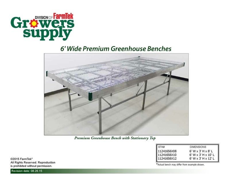
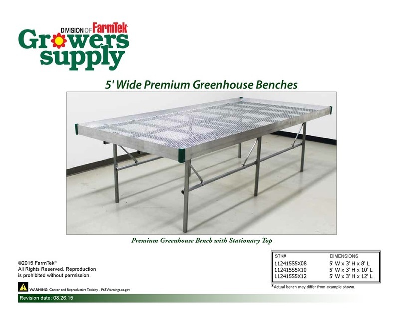
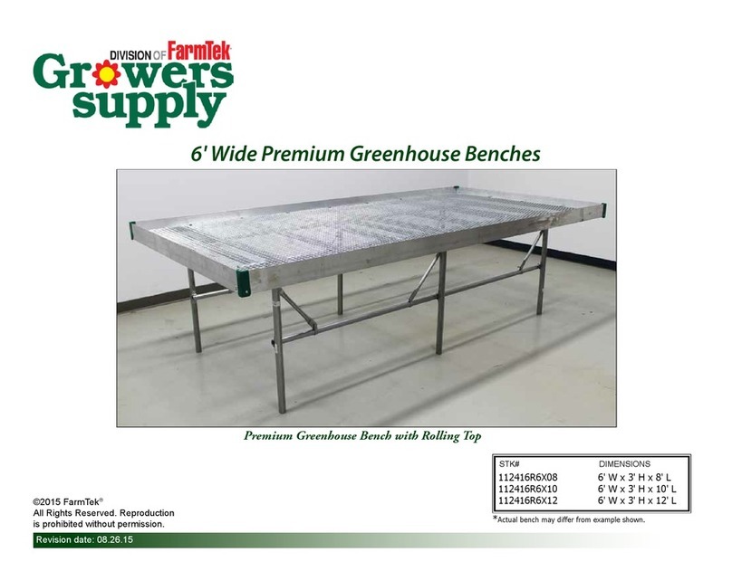
5' Wide Premium Greenhouse Benches
Premium Greenhouse Bench with Rolling Top
STK# DIMENSIONS
112415R5X08 5' W x 3' H x 8' L
112415R5X10 5' W x 3' H x 10' L
112415R5X12 5' W x 3' H x 12' L
*Actual bench may differ from example shown.
2Revision date: 08.26.15
READ THIS DOCUMENT BEFORE YOU BEGIN
Thank you for purchasing this premium greenhouse bench. When properly assembled and maintained, this product will provide years of reliable service. These
instructions include helpful hints and important information needed to safely assemble and properly maintain the bench. Please read these instructions before
you begin. If you have any questions during the assembly, contact Customer Service at 1.800.245.9881 for assistance.
ASSEMBLY PROCEDURE
Following the instructions as presented will help
ensure proper assembly. The steps outlining the
assembly process are as follows:
1. Verify that all parts are included in the shipment.
Notify customer service for questions or
concerns.
2. Read these instructions and all additional
documentation included with the shipment before
you begin.
3. Gather the tools and assistants.
4. For best results, assemble the components on a
flat, level surface in the order they are presented
in these instructions.
5. Read the care and maintenance information.
CARE AND MAINTENANCE
Proper care and maintenance is important.
Check the following items periodically to
properly maintain your bench.
• Check connections and all fasteners to
verify that they remain tight.
• Do not climb or stand on the frame at
anytime.
• Do not use bench without installing the
safety chains for the rolling bench top.
• Verify that all weight on the bench top is
evenly distributed.
• Promptly repair or replace all damaged
parts and frame members.
• If the bench is disassembled and moved,
inspect all parts and connections before
reassembling and use.
• For replacement parts, call 800.245.9881
for assistance.
Important Information
SAFETY PRECAUTIONS
• Wear eye protection.
• Wear gloves when handling metal pipes and top.
• Use a portable GFCI (Ground Fault Circuit
Interrupter) when working with power tools and
cords.
UNPACK AND IDENTIFY PARTS
The following steps will ensure that you have all the
necessary parts before you begin assembly.
1. Unpack the contents of the shipment and place
where you can easily inventory the parts. Refer
to the Bill of Materials/Spec Sheets.
2. Verify that all parts listed on the Bill of Materials/
Spec Sheets are present. If anything is missing
or you have questions, consult the Pictorial
Parts Guide and all diagrams for clarification, or
contact Customer Service.
NOTE: At this time, you do not need to open
the plastic bags containing smaller parts such
as fasteners or washers (if equipped).
REQUIRED TOOLS
The following list identifies the main tools needed to
assemble the bench. Additional tools may be needed.
• Tape measure and marker
• Variable speed drill (cordless with extra batteries
works best)
• Small hammer and gloves
• Level (1' to 2')
• Carpenter's square or similar tool to square frame
• Adjustable and needle-nosed pliers
• Ratchet and socket set
• 7/16" and 1/2" wrench
• Drill bit set to predrill 108553 screw holes
(optional)
WARNING: Bench top can tip! Do not
roll top when weight is all along one
side. Evenly distribute weight before
operation. Never stand on bench top.
QUICK START GUIDE
For an overview of each bench length with
connection details, consult the Quick Start
Guide near the back of this guide.
3
Revision date: 08.26.15
Important Information
PICTORIAL GUIDE
The following graphics and photos will help identify the different parts of your bench. (Some parts may not be shown.)
FA4482B
Tek Screw
108553 Wafer
Head Screw
FAG102B
1/4" x 3/4" Bolt
FALB10B
1/4" Nut
102921B
Neo-Bonded
Washer
QH1070 Pipe
Strap
112391
112815 Poly Corners
for bench top.
112399Lxxxxxx
End and Side Rails
(Length depends on bench.)
QH1400 Band Clamp ST01500D706G19 Strut
AR4112Z10
Chain Single Jack #12
(Rolling benches only.)
100442 (1)
Nut Setter
4
4Revision date: 08.26.15
1
Assembly Instructions
ASSEMBLE BENCH TOP SUPPORTS
Use the photos and information that follows to construct the bench top frame supports. The 12' bench has four (4) support assemblies. The 8' and
10' benches each have three (3) supports. Gather the parts required to complete one (1) support assembly:
• (2) S125P03175 square tube for legs
• (1) S125P045 square tube crossbar
• (4) 112391 four-bolt clamps
• (8) FAG102B (1/4" x 3/4" hex bolts)
• (8) FALB10B (1/4" nuts)
• (12) FA4482B Tek screws
1. Gather the parts. 2. Construct two bracket assemblies. Do not
tighten the bolts at this time.
3. Slide the assembly onto one S125P03175
square tube leg pipe.
4. Set assembly flush with the end of the
square tube.
5. Slide the S125045 crossbar square tube
into the bracket assembly.
IMPORTANT: Set tubes flush with the
ends of the bracket assembly.
5
Revision date: 08.26.15
1
Assembly Instructions
6. Tighten 1/4" bolts. 7. Check square tube position.
9. Check assembly for square. 10. Secure bracket in place using two (2)
more Tek screws.
8. Install one FA4482B Tek screw in center.
11. Flip assembly over and repeat Steps 8-10
to secure remaining tube to brackets.
12. Repeat steps to install remaining bracket. 13. Assemble remaining bench top supports. NOTE: Photo shows assembled support.
The 12' bench has four
support assemblies. The 8'
and 10' benches each have
three supports.
S125P045
6
6Revision date: 08.26.15
Assembly Instructions
2
1. Measure 15-3/4" from the bottom of each leg
and mark the location on the inside edge.
4. Start drilling the mounting hole using an
FA4482B Tek screw if desired, or continue with
Step 5.
2. Have an assistant hold the assembly and
center the pipe strap at the mark. Position the
strap on the inside of the leg pipe. See photo
in Step 4 for location.
5. Secure pipe strap to the leg tube. Do not
overtighten. Doing so will strip threads.
3. Mark one hole position on the leg pipe.
6. Repeat steps to attach all remaining pipe
straps to the inside surface of the frame legs.
ATTACH LOWER PIPE STRAPS
Use the photos and information that follows to attach the QH1070 straps. Attach two QH1070 straps to each bench top support assembly.
QH1070
7
Revision date: 08.26.15
Assembly Instructions
3ASSEMBLE SUPPORT FRAME FOR BENCH TOP
For best results, assemble the support frame on a flat, level surface. Gather the parts for the support frame:
• (6) ST01500D706G19 struts; eight (8) for the 12' bench.
• (6) QH1400 band clamps; eight (8) for the 12' bench.
• (2) 1.315" diameter round pipes. (See Quick Start diagrams for pipe length/ID.)
• FA4482B Tek screws and 102921B neo-bonded washers
1. Take the mid support assembly and insert the
round pipe into the pipe straps attached to the
inside of each vertical frame leg.
NOTE: The 12' frame has two mid supports.
2. At one end of the frame, slide two QH1400
band clamps onto each of the round pipes.
3. Slide the pipes into the end support assembly.
4. Tighten the mounting screws for each of the
pipe clamps. Do not overtighten! Screws
should be snug. Position pipes flush with the
outer edge of each QH1070 pipe strap.
5. Move to the opposite end and slide one band
clamp onto each round pipe. (Slide two clamps
onto each pipe for the 12' long frame.) Attach
the remaining end support to the pipes.
6. Locate and mark the middle of each horizontal
pipe. Align mid support assembly with marks.
For the 12' long frame evenly space the two
mid supports between the end supports.
End Support Mid Support
8
8Revision date: 08.26.15
Assembly Instructions
3ASSEMBLE SUPPORT FRAME FOR BENCH TOP—continued
7. Tighten the pipe strap mounting bolts of
the mid support. Tighten until snug. Do not
overtighten. Doing so will strip the threads.
10. Mark the mounting hole position on the inside
of the vertical frame leg.
8. Check that six (6) band clamps are in position
on the horizontal pipes–eight (8) for the 12'
long bench. See circled clamps above.
11. Start drilling the mounting hole using an
FA4482B Tek screw if desired, or skip to the
next step.
9. Take one strut and attach it to one band clamp.
12. Attach the strut to the tube using the Tek screw
and a 102921B neo-bonded washer.
9
Revision date: 08.26.15
13. Move to the lower strut connection and
reposition band clamp as needed.
16. Move to the mid support and check its position.
Attach the struts to secure that support in
place. Verify that legs are plumb.
17. Repeat for remaining mid support(s).
14. Using a level, verify that the support leg is
plumb/vertical. Adjust support assembly and
strut as needed and tighten band clamp bolt.
18. Move to the final end support assembly and
attach those struts. Verify that round pipe is
flush with the outside edge of pipe straps.
15. Repeat to attach the remaining strut for the
first end support assembly.
19. Return to each pipe strap and install an
FA4482B Tek screw through the strap and into
the pipe.
20. Continue with the next procedure.
Assembly Instructions
3ASSEMBLE SUPPORT FRAME FOR BENCH TOP—continued
10
10 Revision date: 08.26.15
Assembly Instructions
4INSTALL ROLLER PIPES
1. Move to one end support crossbar and
measure 10" in from the bracket at each end of
the crossbar. Mark the points.
3. Set the two roller pipes on the frame.
2. Install one FA4482B Tek screw at each point
marked on the crossbar.
4. Position each pipe between the crossbar
bracket and the Tek screw installed in the
crossbar.
NOTE: These Tek screws function as roller
pipe stops and help keep pipes aligned during
operation.
NOTE: Final adjustment of the roller pipes
takes place after bench top is installed.
Gather the roller pipe parts:
• (2) 1.315" diameter pipes (See Quick Start section for pipe lengths and identification.)
• FA4482B Tek screws
10"
Roller Pipe Stops
11
Revision date: 08.26.15
5ASSEMBLE BENCH TOP
For best results, assemble the bench top frame with an assistant on a flat, level surface. Gather the parts for the support frame:
• (2) 112399L060375 frame end rails–short
• (2) 112399Lxxxxxx frame side rails–long
See Quick Start section for part numbers.
• 125P060 support tubes
• (1) Expanded metal top
• FA4482B Tek screws
• 102921B Neo-bonded washers
1. Select the two end rails and two bench top
support tubes.
4. Position the end rails and marked side rails as
shown.
2. Carefully press one support tube into each of
the end rails and center the tube in the end
rail.
5. Take the remaining support tubes and place in
position as shown.
3. Move to the side rails and mark the on-center
locations of the support tubes for your bench.
Evenly space the remaining support tubes.
6. With assistance, carefully slide each end of
each tube into the side rail channels. Align
with the on-center marks.
Assembly Instructions
12
12 Revision date: 08.26.15
7. Move to the end rails and attach side rails as
shown. Position the channel edges of the side
rail on top of the upper and lower edges of the
end rail channel. See photo above.
10. Move to the side rail, brace one side, and
gently tap the side rail at each support tube to
seat the tubes to the side rails.
8. With assistance, gently tap the rails to seat
the ends at the corner. Verify that the rails are
aligned as shown. Repeat at each corner.
11. Check the support tubes for square and verify
that each is aligned with the on-center marks
on each side rail. Do not install Tek screws at
this time.
9. Using a carpenter's square, square all corners.
Slide the entire frame assembly as needed to
square the frame.
NOTE: Sample frame is shown above. Size
and number of support tubes may differ
from your frame. See diagrams for your
frame near the back of this guide.
5ASSEMBLE BENCH TOP—continued
Assembly Instructions
Side Rail–Long
End Rail–Short
Side Rail–Long
End Rail–Short
13
Revision date: 08.26.15
5
Assembly Instructions
12. With assistance, carefully lift the expanded
metal top and carry it to the assembled frame.
CAUTION: Metal is sharp! Wear gloves to
protect hands.
14. Measure diagonally and adjust frame as
needed until dimensions are similar. Expanded
metal top will sit tight to the tops of frame rails.
13. Lower the expanded metal top into the frame.
Gently tap the frame rails as needed to allow
the top to drop into position. Do not force the
top into place or pound on the expaned metal.
15. Measure to find the center of each end rail and
mark the location.
NOTE: Use a block of wood or small hammer
if needed to lightly tap the frame rails apart to
allow the top to drop into place.
16. Take an FA4482B Tek screw and 102921B
neo-bonded washer and secure expanded
metal top to the end rail. Fastener should be
snug. Do not strip threads.
FA4482B
Tek Screw
102921B
Neo-Bonded
Washer
ATTENTION: Actual bench may differ from what is shown.
Consult the Quick Start Guide for your bench details.
ASSEMBLE BENCH TOP—continued
14
14 Revision date: 08.26.15
17. Continue to install Tek screws and washers
along the side rail at each support tube.
NOTE: Install screws in a position that best
secures both the expanded metal top and the
support tube to the side rails.
Photo shows a Tek screw and washer installed
through the side rail and into the support tube.
FA4482B
Tek Screw
102921B
Neo-Bonded
Washer
5
Assembly Instructions
18. With assistance, carefully lift the assembled
bench top and set it in place on the support
frame. Frame is heavy!
19. Center top on support frame. Ends and sides
should be equal distance from the support
frame.
ASSEMBLE BENCH TOP—continued
20. Install 112815 poly corners using 108553
screws. Predrill holes through poly corners and
metal for best results using a 1/16" drill bit.
15
Revision date: 08.26.15
6ADJUST ROLLER PIPES AND TEST
Assembly Instructions
ATTENTION: Actual bench may differ from what is shown.
Consult the Quick Start Guide for your bench details.
1. Carefully slide the bench top to one side until
the edge aligns with the outside edge of the
support frame crossbar.
NOTE: Square the bench top on the support
as needed to align it with all crossbars.
NOTE: Above photo shows roller pipe
positions when properly adjusted and the
bench top is fully rolled to one side.
2. Verify that the roller closest to the bench
edge is tight to the roller stop installed in the
crossbar. See circle in photo above. Review
Procedure 4 for roller stop photos and position
if needed.
4. Roll bench top to the center and check roller
position. Except for minor adjustments, pipes
are typically centered between the crossbar
bracket and roller pipe stop at each end.
3. Check the remaining roller to verify that it is
tight against the crossarm bracket. See circled
area above.
5. Roll bench top to the opposite side and check
operation. Adjust rollers as needed. When
adjusted correctly, rollers are parallel to each
other.
Outside edge
of crossbar.
Align
Rollers
Dashed lines show roller
pipe stops and inside edges
of crossbar brackets.
Roller Pipes
16
16 Revision date: 08.26.15
4. Take one chain and slide the end over a lower
1/4" bolt of one support assembly.
NOTE: Carefully roll the bench top to the
opposite side to access the bracket.
1. Take the AR4112Z10 length of chain and
measure a 12" section.
5. Squeeze the link around the bolt, add a 1/4"
nut, and tighten to secure the chain.
NOTE: Position so chain hangs down as
shown in the next photo.
2. Using pliers, grip the link and carefully bend
to open it enough to separate the 12" section
from the bulk chain.
6. Verify that the link at the free end is open
enough to hook onto the expanded metal top.
3. Repeat this process to create six (6) 12"
pieces of chain. (The 12' long frame has eight
(8) chains in all.)
7INSTALL SAFETY CHAINS
Assembly Instructions
ATTENTION: Actual bench may differ from what is shown.
Consult the Quick Start Guide for your bench details.
17
Revision date: 08.26.15
10. With pliers, pinch the link to close it around the
expanded metal bench top.
7. Repeat Steps 4-6 to attach the remaining
safety chains—one to the top of each support
assembly.
11. Move to the remaining chains on the same
side and repeat the steps to secure the end of
each chain to the bench top.
8. Carefully roll the bench top to one side. Rollers
will stop against the Tek screws installed in
crossbar. Review Procedure 4 to adjust rollers
if needed.
12. Repeat steps to attach the remaining chains to
the bench top. Roll bench top to test operation.
NOTE: Adjust position of the chains as needed
to prevent them from getting caught on the Tek
screws in the crossbar brackets.
9. Hook the free end of a chain over the
expanded metal top from the underside.
Position chains as needed to prevent contact
with screws on the crossbar brackets.
7
Assembly Instructions
INSTALL SAFETY CHAINS—continued
18 Revision date: 08.26.15
PAGE RESERVED FOR CUSTOMER NOTES AND RECORDS
19
Revision date: 08.26.15
Quick Start Guide
5' x 8'
Premium Bench – Rolling Top
112415R5X08
5' x 10'
Premium Bench – Rolling Top
112415R5X10
5' x 12'
Premium Bench – Rolling Top
112415R5X12
WARNING: Bench top can tip! Do not roll top when weight is all
along one side. Evenly distribute weight before operation.
Never stand on bench top.
20 Revision date: 08.26.15
5' x 8' (112415R5X08) Premium Bench – Rolling Top
S125P045
S125P03175
S125P03175
112391
Bolt Clamp
AB
See next page for 5' x 8'
bench top parts.
ST01500D706G19
Strut
131P072
131P0845
QH1400
Band Clamp
QH1070
Pipe Strap
Roller
Pipes
Roller Pipe Stops
(FA4482B Tek Screws)
B
FA4482B
Tek Screw
QH1070
Pipe Strap
A
FAG102B
Bolt
FALB10B
Nut
112391
Bolt
Clamp

This manual suits for next models

2

Other FarmTek Lawn And Garden Equipment manuals

FarmTek PolyMax 108293 User manual

FarmTek

FarmTek PolyMax 108293 User manual

FarmTek 108681 User manual

FarmTek

FarmTek 108681 User manual

FarmTek Growers Supply HydroCycle 11291950 User manual

FarmTek

FarmTek Growers Supply HydroCycle 11291950 User manual

FarmTek 109912 User manual

FarmTek

FarmTek 109912 User manual

FarmTek Growers Supply GrowSpan Estate Elite 104711 User manual

FarmTek

FarmTek Growers Supply GrowSpan Estate Elite 104711 User manual

FarmTek PolyMax H1-10 User manual

FarmTek

FarmTek PolyMax H1-10 User manual

FarmTek 10712 User manual

FarmTek

FarmTek 10712 User manual

FarmTek HydroCycle 9" Pro Vertical Microgreen System... User manual

FarmTek

FarmTek HydroCycle 9" Pro Vertical Microgreen System... User manual

FarmTek Growers supply Aquaponics System II Instruction manual

FarmTek

FarmTek Growers supply Aquaponics System II Instruction manual

FarmTek Growers Supply 109722 User manual

FarmTek

FarmTek Growers Supply 109722 User manual

FarmTek 110217 User manual

FarmTek

FarmTek 110217 User manual

FarmTek HydroCycle 6 Pro User manual

FarmTek

FarmTek HydroCycle 6 Pro User manual

FarmTek PolyMax 108293S User manual

FarmTek

FarmTek PolyMax 108293S User manual

FarmTek 112415S5X08 User manual

FarmTek

FarmTek 112415S5X08 User manual

FarmTek Mini Brute 108262 User manual

FarmTek

FarmTek Mini Brute 108262 User manual

FarmTek Growers Supply GrowSpan Gothic Premium... User manual

FarmTek

FarmTek Growers Supply GrowSpan Gothic Premium... User manual

FarmTek 104299 User manual

FarmTek

FarmTek 104299 User manual

FarmTek Growers supply 112413S3X08T22 User manual

FarmTek

FarmTek Growers supply 112413S3X08T22 User manual

FarmTek TEK SUPPLY 102487 User manual

FarmTek

FarmTek TEK SUPPLY 102487 User manual

FarmTek 104940 User manual

FarmTek

FarmTek 104940 User manual

FarmTek 103865 User manual

FarmTek

FarmTek 103865 User manual

FarmTek 104479 User manual

FarmTek

FarmTek 104479 User manual

FarmTek 103446 User manual

FarmTek

FarmTek 103446 User manual

FarmTek 113502 User manual

FarmTek

FarmTek 113502 User manual

Popular Lawn And Garden Equipment manuals by other brands

Yanmar RT66 Operator's manual

Yanmar

Yanmar RT66 Operator's manual

Buhler Box Scraper FK351 Operator's & parts manual

Buhler

Buhler Box Scraper FK351 Operator's & parts manual

Fort Defiance LOG-MULE LMB-100 owner's manual

Fort Defiance

Fort Defiance LOG-MULE LMB-100 owner's manual

Miracle-Gro AeroGarden Bounty Quick setup guide

Miracle-Gro

Miracle-Gro AeroGarden Bounty Quick setup guide

Craftsman CMXGZBF7124336 instruction manual

Craftsman

Craftsman CMXGZBF7124336 instruction manual

Garden play GP221 manual

Garden play

Garden play GP221 manual

Green-Qube GQ2030L Assembly instructions

Green-Qube

Green-Qube GQ2030L Assembly instructions

Ryobi ONE + OGS-1801 user manual

Ryobi

Ryobi ONE + OGS-1801 user manual

Keter Duotech user manual

Keter

Keter Duotech user manual

Stinger UV-15 user manual

Stinger

Stinger UV-15 user manual

Yard Machines F-49E Operator's manual

Yard Machines

Yard Machines F-49E Operator's manual

Land Pride RTR1042 Specifications & Capacities

Land Pride

Land Pride RTR1042 Specifications & Capacities

Husqvarna AUTOMOWER 105 Operator's manual

Husqvarna

Husqvarna AUTOMOWER 105 Operator's manual

BCS Action 710 Instruction book

BCS

BCS Action 710 Instruction book

Ogden CA60 Instruction manual and parts list

Ogden

Ogden CA60 Instruction manual and parts list

POLA G 331878 manual

POLA G

POLA G 331878 manual

Dolmar BUM168RFX instruction manual

Dolmar

Dolmar BUM168RFX instruction manual

Bonnington Nature's market BBSOLAR manual

Bonnington

Bonnington Nature's market BBSOLAR manual

manuals.online logo
manuals.online logoBrands
  • About & Mission
  • Contact us
  • Privacy Policy
  • Terms and Conditions

Copyright 2025 Manuals.Online. All Rights Reserved.