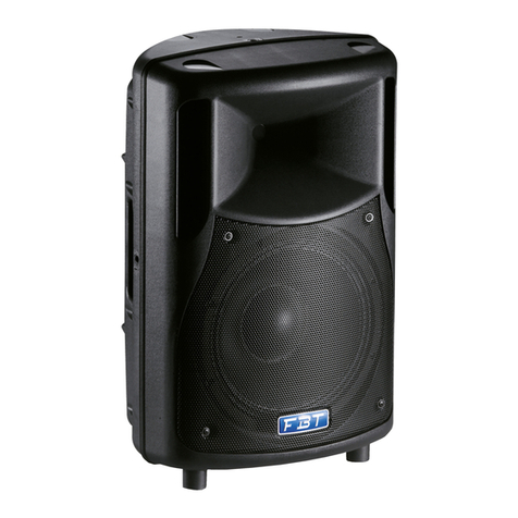
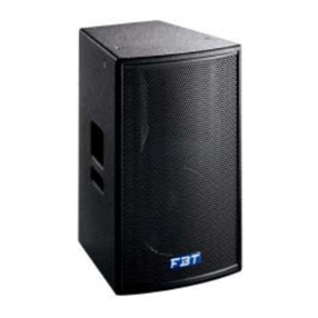
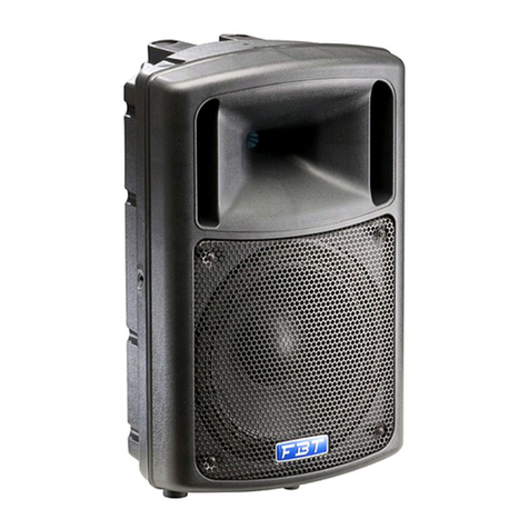
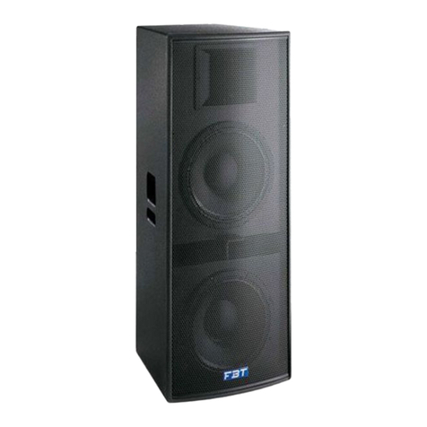
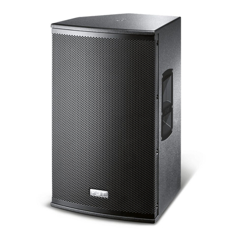
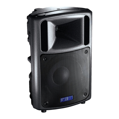
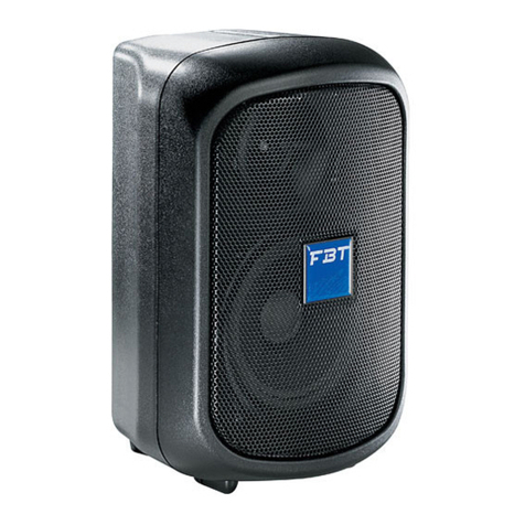
Fbt Maxx 5A User manual

FBTELETTRONICAS.p.A.-ZONAIND.LESQUARTABUE-62019RECANATI(MC)-ITALY
tel.071750591r.a.-fax0717505920-P.O.BOX104-e-mail:[email protected]t-www.fbt.it
19116#270603
Leinformazionicontenuteinquestomanualesonostatescrupolosamentecontrollate;tuttavianonsiassumenessunaresponsabilità
pereventualiinesattezze.LaFBTElettronicaS.p.A.siriservaildirittodimodificarelecaratteristichetecnicheedestetichedeiprodottiin
qualsiasimomentoesenzapreavviso.
Allinformationincludedinthisoperatingmanualhavebeenscrupulouslycontrolled;howeverFBTisnotresponsibleforeventual
mistakes.FBTElettronicaS.p.A.hastherighttoamendproductsandspecificationswithoutnotice.
Lesinformationscontenuesdanscemanuelontétésoigneusement;toutefoisleconstructeurn’estpasresponsabled’éventuelles
inexactitudes.LaFBTElettronicaS.p.A.s’octroieledroitdemodifierlesdonnéestechniquesetl’aspectesthétiquedesesproduitssans
avispréalable.
AlleinformationenindieserBedienungsanleitungwurdennachbestemWissen;Daherkönnensiealszuverlässigangesehenwerden.
FüreventuelleFehlerûbernimmtFBTaberkeineHaftung.FBTElettronicaS.p.A.BehältsichdasRechtaufÄnderungderProdukteund
Spezifikationenvor.
I
UK
F
D
Manualed’uso
Moded’emploi
Operatingmanual
Benutzer-Handbuch
400W-SOUNDREINFORCEMENTMONITOR
FBTMaxX5aFBTMaxX5a
12 15 15 01212 15 15 1012
HFPWRGND
LIFT IN LINK OUT GAIN HIGH MID LOW VOL LF
ADAP 12 15 15 01212 15 15 1012
HFPWRGND
LIFT IN LINK OUT GAIN HIGH MID LOW VOL LF
ADAP
Connessionedi2FBTMaxX5ainparallelo
Connexionde2FBTMaxX5areliésenparallèle
Connectionof2FBTMaxX5ainparallelmode
Anschluss2parallelgeschalteterFBTMaxX5a
12 15 15 01212 15 15 1012
HFPWRGND
LIFT IN LINK OUT GAIN HIGH MID LOW VOL LF
ADAP 12 15 15 01212 15 15 1012
HFPWR GND
LIFT IN LINK OUT GAIN HIGH MID LOW VOL LF
ADAP
PICKUP18X
MAINOUT
IN IN
L
RMIXER
Configurationdebase:lessorties
généralesG/Ddumixeurdansles
prisesd’entréeXLR-Jack(combo)
delaFBTMaxX5a
Basiskonfiguration:die
allgemeinenL/R
AusgängedesMischpults
mitdenEingangsbuchsen
XLR-Jack(combo)von
FBTMaxX5averbinden.
FBTMaxX5a FBTMaxX5a
EXEMPLESDECONNEXION
ANSCHLUSSBEISPIELE ESEMPIDICOLLEGAMENTO
CONNECTIONEXAMPLES
Configurazionebase:leuscite
generaliL/Rdelmixercollegate
nellepresediingressoXLR-Jack-
CombodelleFBTMaxX5a
Basicconfiguration:the
masterL/Routputsofthe
mixerareconnectedto
theXLR-Jack-Combo
socketoftheFBTMaxX5a
12 15 15 01212 15 15 1012
HFPWRGND
LIFT IN LINK OUT GAIN HIGH MID LOW VOL LF
ADAP
12 15 15 01212 15 15 1012
HFPWR GND
LIFT IN LINK OUT GAIN HIGH MID LOW VOL LF
ADAP 12 15 15 01212 15 15 1012
HFPWRGND
LIFT IN LINK OUT GAIN HIGH MID LOW VOL LF
ADAP
12 15 15 01212 15 15 1012
HFPWRGND
LIFT IN LINK OUT GAIN HIGH MID LOW VOL LF
ADAP 12 15 15 01212 15 15 1012
HFPWRGND
LIFT IN LINK OUT GAIN HIGH MID LOW VOL LF
ADAP 12 15 15 01212 15 15 1012
HFPWRGND
LIFT IN LINK OUT GAIN HIGH MID LOW VOL LF
ADAP
ConfigurationdeplusieursenceintesFBTMaxX5aenutilisantlaprisedesortieXLR
“OUT”enparallèle(link)avecl’entréeCombo“IN”.
KonfigurationmehrererFBTMaxX5aLautsprecherdurchparalleleSchaltungder
XLR“OUT”Ausgangsbuchse(link)mitdem“IN”Eingang.
MAINOUT
OUT
IN
OUT
IN
LR
MIXER
PICKUP18X
FBTMaxX5a
ConfigurazionedipiùdiffusoriFBTMaxX5autilizzandolapresadiuscitaXLROUTin
parallelo(link)conl’ingressoComboIN
ConfigurationofmultipleFBTMaxX5aconnectionthroughtheXLRoutsocketOUT
inparallel(link)withtheXLR-Jack-ComboINsocket
MIXER
ÄUBERER
VERSTÄRKER
AMPLIFICATEUR
EXTERNE
LINK LINK
OUTPUTS
INPUTS
Ch1
Ch1
Ch2
Ch2
FBTMaxX5
MIXEURAMPLIFIÉ
VERSTÄRKTES
MISCHPULT
FBTMaxX5
Configurationdedeuxenceintes
acoustiquespilotéesparunmixeur
amplifié
Konfigurationvonzweiüberein
verstärktesMischpultgesteuerten
Lautsprechern
Configurationdedeuxenceintes
acoustiquespilotéesparunmixeuretun
étagefinaldepuissance
Konfigurationvonzweiüberein
MischpultundeineLeistungsendstufe
gesteuertenLautsprechern
Configurazionedi2diffusoriacustici
pilotatidaunmixeramplificato
Configurationof2FBTMaxX5drivenbya
poweredmixer
Configurazionedi2diffusoriacustici
pilotatidaunmixereunfinaledi
potenza
Configurationof2FBTMaxX5drivenbya
poweramplifierconnectedtoamixer

PEREVITAREILRISCHIODISHOCKELETTRICO
NONAPRIREILCOPERCHIO
NONUSAREUTENSILIMECCANICIALL'INTERNO
CONTATTAREUNCENTRODIASSISTENZAQUALIFICATO
PEREVITAREILRISCHIODIINCENDIOODISHOCKELETTRICO
NONESPORREL'APPARECCHIATURAALLAPIOGGIA
OALL'UMIDITA'
!
ATTENZIONE
RISCHIODISHOCKELETTRICO
NONAPRIRE
°Primadialimentareildiffusoreassicuratevichelatensionedi
alimentazionenonsiasuperioreaquellariportatanelpannelloposteriore
°Nontoglietelaretemetallicadiprotezionedell’altoparlante:toccarlocon
oggettioconlestessemanipotrebbearrecaredanniirreparabili
°Evitateditenereilsistemaespostoperlungotempoall’azionediagenti
atmosfericiqualiumidità,fortivariazioniditemperatura,eccessodicalore,
ecc.
°Evitatel’accumulodipolveree,perquantopossibile,proteggetelo,peril
trasporto,conilsuoimballooriginale
°Incasodicattivofunzionamentodiqualsiasidispositivodelsistema,
affidatevialpiùvicinocentrodiassistenzaFBToadunaltrocentro
specializzato,evitandodiprovvederepersonalmente
INTRODUZIONE
INTRODUCTION
TOREDUCETHERISKOFELECTRICSHOCK
DONOTREMOVECOVER(ORBACK)
NOUSERSERVICEABLEPARTSINSIDE
REFERSERVICINGTOQUALIFIEDSERVICEPERSONNEL
TOREDUCETHERISKOFFIREORELECTRICSHOCK
DONOTEXPOSETHISEQUIPMENTTORAINORMOISTURE
!
WARNING
RISKOFELECTRICSHOCK
DONOTOPEN
°Beforepoweringthespeakersystemmakesurethatthemainspower
voltageisnothigherthanthatshownontherearpanel
°Donotremovethefrontmetalgrillewhichprotectstheloudspeaker;
avoidtouchingitwithanyserviceablepartstopreventanyirreparable
damage
°Avoidexposingthesystemtotheactionofatmosphericagentsforalong
time(dampness,excessiveheat,strongtemperaturevariations,etc.)
°Cleanthesystemonceinawhiletoavoidexcessivedust;whenpossible
protectthesysteminsideitsoriginalpackagingforanytransportpurpose
°Intheeventofmalfunctionofanypartofthesystem,contactthenearest
FBTservicecentreorotherspecialisedcentres,butnevertrytocarryout
repairsyourself
IUK
LanuovagenerazionedidiffusoriacusticiFBTMaxXèrealizzatain
polipropileneconstampaggioadiniezioneagascheconsentediottenere
unprodottoultraleggeromanelcontempoestremamenterobusto.Il
particolaredesignpermetteunamultifunzionalitàdiutilizzointuttiisistemi
diamplificazioneaudio-professionali:comemonitordapalco,per
l’installazioneapareteosoffitto.IlnuovosistemaA.D.A.P.(Advanced
DynamicActiveProtection)diprotezioneelettronicadeitrasduttori,
assicuralamassimagaranziadifunzionamentoinsituazionidiutilizzo
impossibiliadunnormalediffusoresonoro.
Ilfinaledipotenzapresenteall’internodellaFBTMaxX5aprogettatocon
tecnologiaPWM(PulseWidthModulation)permettediridurreilpesoin
rapporto1:3,raggiungendounaefficienzatrevoltesuperiorerispettoad
unatecnologiatradizionale;l’altoparlantecustomB&Cda380mmcon
magneteal“neodymium”ecestelloinalluminiodie-cast.
FBTMaxXèunconnubioperfettotrapotenza,meccanicaetecnologia
d’avanguardia.LaserieFBTMaxXcomprendeilmodelloamplificato
FBTMaxX5a(400Wperilwoofer,100Wperildriver-tromba)eilmodello
FBTMaxX5(400W,confiltroelettronicoattivoda24dB/oct)
ThenewgenerationofFBTMaxXspeakersfeaturesgasinjectionmoulded
cabinetstoachievecompactbutsturdyproducts.Thespecialdesignwith
flowinglinesandroundededgesenablesmultifunctionaluseinallaudio-
professionalamplificationsystems:asstagemonitor,forwallorceiling
mounting,andwithspecialadapterstoenablecabinetstacking.
ThenewA.D.A.P.(AdvancedDynamicActiveProtection)processorensures
totalprotectionofthetransducersandimprovementoftheacoustic
response.
OutputstagesforlowfrequencyunitwithPWM(PulseWidthModulation)
technologyenablesreductioninweightontheratioof1:3,toachievethree
timesgreaterefficiencythanconventionaltechnology;the15”ultra-light
customB&Clowfrequencydriverfeaturesneodymiummagnetanddie-cast
aluminiumframe.
FBTMaxXspeakersystemistherightsynthesisofpower,project
developmentandtremendoustechnology.
TheFBTMaxXseriesincludesmodelFBTMaxX5a(bi-amplified
version:400WfortheLF,100WfortheHF)andmodelFBTMaxX5(400W,with
electronicactivefilterof24dB/oct.).
Mod.BOX104(ORIZZONTALE)
1.
2.
3.
Selezionareconcural’areadoveinstallareidiffusori;assicurarsichelastrutturasia
adeguataasopportareilpesodelbox;fissarelabasedellastaffaalmuroutilizzando
appropriatevitisututtii6foridifissaggiodellastaffa.
Posizionareildiffusoretraiduebraccidellastaffaefissarlotramiteidueinsertifilettati
da10MA
Ruotareildiffusorenellaposizionedesideratautilizzandol’insertofilettatoda6MA
Mod.BOX105(VERTICALE)
1.
2.
3.
Selezionareconcural’areadoveinstallareidiffusori;assicurarsichela
strutturasiaadeguataasopportareilpesodelbox;fissarelabasedella
staffaalmuroutilizzandoappropriatevitisu
tuttii6foridifissaggiodellastaffa.
Posizionareildiffusoretrai
duebraccidellastaffaefissarlo
tramiteidueinsertifilettatida
10MA
Ruotareildiffusorenella
posizionedesiderata
utilizzandolacatena(cheavràanchela
funzionedisicurezza)
provvistadi2moschettonidi
aggancioe1golfare(A)da
inserirenell’appositopunto
diancoraggio.
ISTRUZIONIDIMONTAGGIODELLESTAFFEAMURO WALLBRACKETASSEMBLYINSTRUCTIONS
ATTENZIONE:
PERPREVENIREDANNIAPERSONEECOSEÈINDISPENSABILE
DOTAREILSISTEMADICATENADISICUREZZAQUANDOILBOX
VIENEFISSATOAMURO
CAUTION:
TOAVOIDDAMAGEORPHYSICALINJURYALWAYSENSURETHAT
THESYSTEMISEQUIPPEDWITHASAFETYCHAINWHENTHE
BOXISSECUREDTOTHEWALL
TOPVIEW
10MA 10MA
A
SIDEVIEW
A
Mod.BOX104(HORIZONTAL)
1.
2.
3.
Takecarewhenselectingtheplaceofspeakerinstallation;ensurethestructureis
adequatetowithstandtheweightofthebox;fixthebaseofthebrackettothewallusing
suitablescrewsinall6bracketfixingholes.
Positionthespeakerbetweenthetwobracketarmsandsecurebymeansofthetwo
10MAthreadedinserts
Rotatethespeakertotherequiredpositionusingthe6MAthreadedinsert
Takecarewhenselectingtheplaceofspeaker
installation;ensurethestructureisadequatetowithstand
theweightofthebox;fixthebaseofthebracketto
thewallusingsuitablescrewsinall6bracket
fixingholes.
Positionthespeakerbetweenthetwobracket
armsandsecurebymeansofthetwo10MA
threadedinserts
Rotatethespeakertotherequiredposition
usingthechain(whichalsoactsasasafety
device)equippedwith2snaphooksand1eyebolt
(A)tobeinsertedintherelativeanchorpoint.
Mod.BOX105(VERTICAL)
1.
2.
3.
DIAGRAMME
DIAGRAMS
ORIZZONTALE
HORIZONTAL
(Hz)
180 170 160 150 140
130
120
110
100
90
80
70
60
50
40
30
20
10
0
350
330
320
310
300
290
280
270
260
250
240
230
220210 200 190
340
-27
-33
-21
-15
-9
-3
3
180 170 160 150 140
130
120
110
100
90
80
70
60
50
40
30
20
10
0
350
330
320
310
300
290
280
270
260
250
240
230
220210 200 190
340
-27
-33
-21
-15
-9
-3
3
4ohm
VERTICALE
VERTICAL
(Hz)
180170 160 150140
130120
110
100
90
80
70
60
50
40
30
20
10
0
350
330
320
310
300
290
280
270
260
250
240
230
220210 200 190
340
-27
-33
-21
-15
-9
-3
3
180170 160 150140
130120
110
100
90
80
70
60
50
40
30
20
10
0
350
330
320
310
300
290
280
270
260
250
240
230
220210 200 190
340
-27
-33
-21
-15
-9
-3
3
250
500
1000
2000
4000
8000
12500
16000
Qfactor,Dindex Q(f)DI(f)
1
10
100
100 1000 10000 100000
FREQUENCYRESPONSE
INPUTIMPEDANCE
8ohm
180 170 160 150 140
130
120
110
100
90
80
70
60
50
40
30
20
10
0350
330
320
310
300
290
280
270
260
250
240
230
220210 200 190
340
-27
-33
-21
-15
-9
-3
3
180 170 160 150 140
130
120
110
100
90
80
70
60
50
40
30
20
10
0
350
330
320
310
300
290
280
270
260
250
240
230
220210 200 190
340
-27
-33
-21
-15
-9
-3
3
250
500
1000
2000
4000
8000
12500
16000
ORIZZONTALE
HORIZONTAL
(Hz)
VERTICALE
VERTICAL
(Hz)
180 170 160 150 140
130120
110
100
90
80
70
60
50
40
30
20
10
0350
330
320
310
300
290
280
270
260
250
240
230
220210 200 190
340
-27
-33
-21
-15
-9
-3
3
180 170 160 150 140
130120
110
100
90
80
70
60
50
40
30
20
10
0
350
330
320
310
300
290
280
270
260
250
240
230
220210 200 190
340
-27
-33
-21
-15
-9
-3
3
FREQUENCYRESPONSE
INPUTIMPEDANCE
Qfactor,Dindex Q(f)DI(f)
1
10
100
100 1000 10000 100000

Mod.BOX104(HORIZONTAL)
1.
2.
3.
DenInstallationsortderLautsprechersorgfältigwählen;sicherstellen,dassdie
StrukturfürdasGewichtderLautsprecherboxengeeignetist;passendeSchrauben
inalle6BohrungendesBügelseinsetzenunddieBasisdesHaltebügelsander
Wandbefestigen.
DenLautsprecherzwischenden
beidenArmendesHaltebügels
anbringenundmitdenbeiden
10MA-Gewindebuchsen
befestigen.
DenLautsprechermitHilfe
der6MA-Gewindebuchsein
diegewünschtePosition
drehen.
Mod.BOX104(HORIZONTAL)
1.
2.
3.
Sélectionnerattentivementl'endroitoùlesenceintesserontinstallées;s'assurer
quelastructuresoitenmesuredesupporterlepoidsducaisson;fixeraumurla
basedelabrideàl'aidedevisadéquatessurles6trousdefixationdelabride.
Placerl'enceinteentrelesdeuxbrasde
labrideetlafixerentrelesdeuxpièces
intercalairesfiletéesde10MA
Tournerl'enceintedansla
positionvoulueenutilisantla
pièceintercalairefiletéede6MA
Mod.BOX105(VERTICAL)
1.
2.
3.
Sélectionnerattentivementl'endroitoù
lesenceintesserontinstallées;s'assurer
quelastructuresoitenmesuredesupporter
lepoidsducaisson;fixeraumurlabasede
labrideàl'aidedevisadéquatessurles6trousde
fixationdelabride.
Placerl'enceinteentrelesdeuxbrasdelabrideet
lafixerentrelesdeuxpiècesintercalairesfiletéesde
10MA
Tournerl'enceintedanslapositionvoulueen
utilisantlachaîne(quiauraaussiunefonctionde
sécurité)muniededeuxmousquetonsd'accrochage
etd'unechevilleàoeillet(A)àintroduiredanslepoint
defixationspécial.
Mod.BOX105(VERTIKAL)
1.
2.
3.
DenInstallationsortderLautsprecher
sorgfältigwählen;sicherstellen,dassdie
StrukturfürdasGewichtder
Lautsprecherboxengeeignetist;passende
Schraubeninalle6Bohrungendes
BügelseinsetzenunddieBasis
desHaltebügelsanderWand
befestigen.
DenLautsprecherzwischenden
beidenArmendesHaltebügels
anbringenundmitdenbeiden
10MA-Gewindebuchsen
befestigen.
DenLautsprechermitHilfeder
Kette(dieauchSicherheitsfunktion
hat),dieüber2Karabinerhakenund
1Ringschraube(A)zumEinsetzen
indenBefestigungspunktverfügt,in
diegewünschtePositiondrehen.
POURÉVITERLERISQUEDECHOCÉLECTRIQUE
NEPASOUVRIRLECOUVERCLE
NEPASUTILISERD’OUTILSMÉCANIQUESÀL’INTÉRIEUR
CONTACTERUNCENTRED’ASSISTANCEQUALIFIÉ
POURÉVITERLERISQUED’INCENDIEOUDECHOCÉLECTRIQUE
NEPASEXPOSERL’APPAREILLAGEÀLAPLUIEOUÀL’HUMIDIT
RISQUEDECHOCÉLECTRIQUE
NEPASOUVRIR
°Vérifiezquelatensiond’alimentationnesoitpassupérieureàlavaleur
indiquéederrièrel’appareil
°Evitezdetoucherlescônesdeshauts-parleursdesavecl’unoul’autre
objectouaveclesmains,cardesdommagesirréparablespourraientse
produire
°Evitezdelaisserexposertroplongtempslesbafflesàl’actiondesagents
atmosphériques(humidité,fortesvariationsdetempérature,excèsde
chaleur,etc...)
°Evitezl’accumulationdepoussièreetpourletransportprotégez-les,si
possible,avecleuremballaged’origine
°Encasdemauvaisfonctionnementd’undesdispositifsdusystème,
adressez-vousaucentred’assistanceFBTleplusprocheouàuncentre
spécialiséetévitezd’intervenirpersonnellement
INTRODUCTION
EINLEITUNG
STROMSCHLAGGEFAHRNICHTDENDECKELÖFFNEN
WENDENSIESICHANEINENQUALIFIZIERTENKUNDENDIENST
UMRISIKENVONSTROMSCHLAGUNDBRANDAUSZUSCHLIESSEN
SETZENSIEDASGERÄTKEINEMREGENODERFEUCHTIGKEITAUS
STROMSCHLAGGEFAHR
NICHTÖFFNEN
°VordemSpeisenderLautsprecherboxsicherstellen,dasihre
BetriebsspannungmitderNetzspannungübereinstimmt
°VermeidenSie,dieKegelderLautsprechermitirgndeinemGegenstand
odermitdenHändenzuberühren:eskönntennichtreparierbareSchäden
entstehen
°VermeidenSie,dieakustischenBoxenfürlängereZeitden
Witterungseinflüssenauszusetzen(Feuchtigkeit,starke
Temperaturschwankungen,ÜbermaßanHitzeusw.)
°VermeidenSieebensostarkeStaubansammlungenundbenutzenSie,
soweitwiemöglich,dieOriginalverpackungfürdenTransport
°ImFalleeinesfehlerhaftenAblaufseinerdervorhandenen
EinrichtungendesSystems,wendensiebitteandennächstliegenden
KundendienstderFBToderaneinFachgeschäft;vermeidenSie
Eigenreparaturen
FD
Lanouvellegénérationd'enceintesacoustiquesMaxXaétéréaliséeen
polypropylènemoulésousinjectiondegaz:cettetechniquepermet
d'obtenirunproduitultra-légeretenmêmetempsextrêmementrobuste.
Ledesignparticulierpermetdemultiplesutilisationsavectousles
systèmesd'amplificationaudioprofessionnels:moniteursdescène,
installationcontreuneparoiouauplafond.LenouveausystèmeADAP
(AdvancedDynamicActiveProtection,c'est-à-diredeprotection
électroniquedestransducteurs)garantitunfonctionnementparfaitdans
touteslessituationsd'utilisation,mêmelesplusdifficilespourune
enceinteacoustiquenormale.L'étagefinaldepuissance,montédans
l'enceinteFBTMaxX5a,adoptelatechnologiePWM(PulseWidth
Modulation):ellepermetderéduirededeuxtierslepoidstouten
atteignantuneefficacitétroisfoissupérieureàcelledelatechnologie
traditionnelle;lehaut-parleurcustomestun15”B&Cavecaimantau
"neodymium"etsaladierenaluminiummoulésouspression.FBTMaxX
représentelemariageparfaitentrepuissance,mécaniqueettechnologie
d'avant-garde.LasérieFBTMaxXcomprendlemodèleamplifiéFBTMaxX
5a(400Wpourlewoofer,100Wpourledriver-pavillon)etlemodèle
FBTMaxX5(filtrepassif400W).
DieneueGenerationvonLautsprecherboxenFBTMaxXistaus
gasgespritztemPolypropylenundsomitsuperleicht,gleichzeitigaber
auchäußerstrobust.DurchdasexklusiveDesignwerdenflexible
AnwendungsmöglichkeiteninsämtlichenprofessionellenAudio-
Verstärkungssystemen,zumBeispielinBühnenmischpulten,fürWand-
bzw.Deckeninstallationgeboten.DasneueelektronischeADAP
(AdvancedDynamicActiveProtection)SchutzsystemderTransmitter
sorgtfürhöchsteBetriebssicherheitselbstbeidenAnwendungen,in
denennormaleBoxenpassenmüssen.DiemitPWMTechnologie(Pulse
WidthModulation)entwickelteLeistungsendstufeindenFBTMaxX5a
LautsprecherngestatteteineGewichtsreduzierungimVerhältnis1:3,
wobeiaußerdemeinedreifacheLeistungsfähigkeitgegenüberherkö
mmlichenVerfahrenstechnikenerzieltwird;beimCustomLautsprecher
handeltessichumeinen15"B&Cmit"Neodymium"MagnetundKorb
ausSpritzgussaluminium.FBTMaxXistdieperfekteKombinationvon
Leistung,MechanikundfortschrittlicherTechnologie.DieSerie
FBTMaxXbeinhaltetdasverstärkteModellFBTMaxX5a(400Wfür
Tieftöner,100WfürHochtonhorn)unddasModellFBTMaxX5(400W
Passivfilter).
10MA 10MA
SIDEVIEW
A
A
INSTRUCTIONSPOURLEMONTAGEMURALDESBRIDES MONTAGEANLEITUNGDERWANDBÜGEL
ATTENTION:
POURÉVITERDECAUSERDESDOMMAGESA’DESPERSONNESET
DESOBJETS,ILESTINDISPENSABLED’ÉQUIPERLESYSTÈME
D’UNECHAÎNEDESÉCURITÉLORSQUELECAISSONESTFIXÉAU
MUR
ACHTUNG:
ZURVERMEIDUNGVONPERSONEN-UNDSACHSCHÄDENMUSS
DASSSYSTEMBEIEINERWANDBEFESTIGUNGDER
LAUTSPRECHERBOXUNBEDINGTMITEINERSICHERHEITSKETTE
AUSGESTATTETWERDEN
TOPVIEW
DIAGRAMMI DIAGRAMS
180 170 160 150140
130120
110
100
90
80
70
60
50
40
30
20
10
0350
330
320
310
300
290
280
270
260
250
240
230
220210200 190
340
-27
-33
-21
-15
-9
-3
3
4000
180 170 160 150140
130120
110
100
90
80
70
60
50
40
30
20
10
0
350
330
320
310
300
290
280
270
260
250
240
230
220210 200 190
340
-27
-33
-21
-15
-9
-3
3
250
180 170 160 150140
130120
110
100
90
80
70
60
50
40
30
20
10
0350
330
320
310
300
290
280
270
260
250
240
230
220210 200 190
340
-27
-33
-21
-15
-9
-3
3
8000
180 170 160 150140
130
120
110
100
90
80
70
60
50
40
30
20
10
0
350
330
320
310
300
290
280
270
260
250
240
230
220210 200 190
340
-27
-33
-21
-15
-9
-3
3
500
180 170 160 150 140
130120
110
100
90
80
70
60
50
40
30
20
10
0350
330
320
310
300
290
280
270
260
250
240
230
220210200 190
340
-27
-33
-21
-15
-9
-3
3
12500
180 170 160 150 140
130120
110
100
90
80
70
60
50
40
30
20
10
0
350
330
320
310
300
290
280
270
260
250
240
230
220210200 190
340
-27
-33
-21
-15
-9
-3
3
1000
180 170 160 150 140
130120
110
100
90
80
70
60
50
40
30
20
10
0350
330
320
310
300
290
280
270
260
250
240
230
220210200 190
340
-27
-33
-21
-15
-9
-3
3
16000
180 170 160 150140
130120
110
100
90
80
70
60
50
40
30
20
10
0
350
330
320
310
300
290
280
270
260
250
240
230
220210 200 190
340
-27
-33
-21
-15
-9
-3
3
2000
ORIZZONTALE
HORIZONTAL
(Hz)
250
180 170 160 150140
130
120
110
100
90
80
70
60
50
40
30
20
10
0
350
330
320
310
300
290
280
270
260
250
240
230
220210 200 190
340
-27
-33
-21
-15
-9
-3
3
2000
180 170 160 150140
130120
110
100
90
80
70
60
50
40
30
20
10
0350
330
320
310
300
290
280
270
260
250
240
230
220210 200 190
340
-27
-33
-21
-15
-9
-3
3
1000
180 170 160 150 140
130120
110
100
90
80
70
60
50
40
30
20
10
0350
330
320
310
300
290
280
270
260
250
240
230
220210200 190
340
-27
-33
-21
-15
-9
-3
3
4000
180170 160 150140
130120
110
100
90
80
70
60
50
40
30
20
10
0350
330
320
310
300
290
280
270
260
250
240
230
220210 200 190
340
-27
-33
-21
-15
-9
-3
3
8000
180170 160 150140
130120
110
100
90
80
70
60
50
40
30
20
10
0350
330
320
310
300
290
280
270
260
250
240
230
220210 200 190
340
-27
-33
-21
-15
-9
-3
3
12500
180 170 160 150140
130120
110
100
90
80
70
60
50
40
30
20
10
0350
330
320
310
300
290
280
270
260
250
240
230
220210 200 190
340
-27
-33
-21
-15
-9
-3
3
VERTICALE
VERTICAL
(Hz)
180 170 160 150140
130120
110
100
90
80
70
60
50
40
30
20
10
0
350
330
320
310
300
290
280
270
260
250
240
230
220210 200 190
340
-27
-33
-21
-15
-9
-3
3
500
16000
180 170 160 150 140
130120
110
100
90
80
70
60
50
40
30
20
10
0350
330
320
310
300
290
280
270
260
250
240
230
220210200 190
340
-27
-33
-21
-15
-9
-3
3
FREQUENCYRESPONSE
-10
-30
-50
-70
db Freq.
gradi
vertical-6dbbeamwidth -18--6 -6-6
10
30
50
70 horizontal-6dbbeamwidth -18--6 -6-6
-10
-30
-50
-70
gradi
10
30
50
70
db Freq.
Qfactor,Dindex
Q(f)
DI(f)
1
10
100
100 1000 10000 100000

IUK
CONNESSIONI/CONNECTIONS
SPECIFICHETECNICHE/TECHNICALSPECIFICATIONS
CONTROLLI CONTROLS
LatosaldatureLatocontatti
1.Massa
2.Fase+
3.Fase-
Schermo(Shield)
Caldo(Hot)
Freddo(Cold)
1+ PositivePositivo/
1- NegativeNegativo/
PresaSpeakon
Jackstereo/bilanciato/balanced
#IN-link-OUT
#GAIN
#HIGH/MID/LOW
#VOL
#GNDLIFT
.
A.D.A.P
PWR:
:Presediingressoeduscitabilanciateelettronicamente.La
presa“IN”XRL+Jack-Combo-consenteilcollegamentoadunsegnale
preamplificatocomequelloinuscitadaunmixer;l’uscita“OUT”XLRè
connessainparallelo(link)conl’ingresso“IN”permettendoilcollegamentodi
piùdiffusoriconlostessosegnale.
:Regolalapreamplificazionedel
segnaleprovenientedall’ingresso“IN”
ottimizzandolaalcorrettofunzionamento
delcircuitodicanale.Perunaequilibrata
regolazionedelGain,posizionarela
manopoladelVolumeacirca3/4dellasua
corsainsensoorario,eregolareilGain.
:Controlliditonoche
permettonodimodificarelatimbricadel
suono.Icontrolliditonosonoposti
elettronicamentedopoilcontrollodel
Gainelaloroesaltazionepuòprovocare
lasaturazionedelcanale:inquestocaso
occorreagiresulcontrollodelGain.Conla
manopolainposizionecentrale(0)non
avvienealcunaalterazionetimbrica.
:Potenziometrodivolumeche
regolaillivellogeneraledelsegnale.
Normalmentelemiglioriprestazionisi
ottengonoconlamanopolaposizionataa
circa3/4dellasuacorsaeconilGain
regolatoinmododaottenereillivello
desiderato.:Interruttoreperla
separazioneelettricatrailcircuitodi
massaeilcircuitoditerra.Conilpulsante
premuto(on)lamassadeisegnaliin
ingressovieneelettricamentescollegata
dalcircuitoditerra(identificatonellochassis);nelcasosimanifestiunronziosul
diffusorequestaposizioneprovvedeadapriregli“anellidimassa”,spesso
causaditalidisturbi.Conilpulsanterilasciatolamassadeisegnaliiningresso
vieneelettricamentecollegataalcircuitoditerradell’apparecchio(identificato
nellochassis).
:Processoreperlaprotezionedeitrasduttoridalle eccessivetensioni;
quandoilsegnaleaudioraggiungelasogliadipericolopericomponentiil
sistemaintervieneautomaticamenteattenuandolatensionedelsegnale
riportandoloaldisottodeilimiti:itempidireazionedelsistemasono
rapidissimi.NeldiffusoreFBTMaxXsonopresentiduecircuitidicontrollo
separati,perlealteebassefrequenze;laloroentratainfunzioneviene
segnalatadall’accensionedeileds“HF”e“LF”.
Ledchesegnalal’accensionedelsistema.
UTILIZZAREILGROUNDLIFTSOLOPERSEGNALI
BILANCIATI
SONOSCONSIGLIATICOLLEGAMENTI
SBILANCIATIONDEEVITAREFASTIDIOSIINCONVENIENTI(ronzii,
rumori,ecc.)
#INlinkOUT:
OFF-
BALANCECONNECTIONSARENOTRECOMMENDEDTOAVOID
DEFECTIVEPERFORMANCE(buzzing,noise,etc.).
#GAIN:
#HIGH/MID/LOW:
#VOL:
#GNDLIFT:
#A.D.A.P.:
#PWR:
Inputandoutputsockets,electronicallybalanced.The
“IN”XLR+Jackcombosocketallowsconnectionofapre-amplifiedsignalsuch
asamixerlineout;the“OUT”socketisconnectedinparallel(link)withtheinput
“IN”allowingmultipleconnectionofmoresystemswiththesamesignal.
regulatespre-amplificationofthesignalcomingfromtheinput“IN”,
ensuringperfectoperationofthechannel
circuits.Forawell-balancedgain
adjustment,settheVolumetoapprox¾
clockwise,thenadjustthegain
accordingly. 3-bandequalisationto
modifythesoundtone.Thesecontrolsare
electronicallypost-gainandifboostedcan
clipthechannel:inthiscaseadjustthegain
controlanticlockwise.Whenthe
potentiometersaresetto“0”thetone
remainsunchanged.
volumepotentiometertocontrol
thechannelsignallevel.Normallyoptimal
channelcircuitperformanceisachieved
withtheknobpositionedatapprox.¾
clockwiseandthegaincontrolsettothe
desiredlevel. 2-positionselectorfor
separatingthesignalsourcegroundand
theamplifiergroundcircuits.ON:the
signalgroundiselectricallydisconnected
fromtheamplifiergroundcircuit(the
chassis).Ifhumisheardinthe
loudspeakers,theONpositionbreaksthe
groundloop,oftenthecauseofthis
interference.OFF:thegroundoftheinput
signalsiselectricallyconnectedtothe
amplifiergroundcircuit(thechassis).USEGROUNDLIFTONLYWITH
BALANCEDSIGNALS.
processorcircuitwhichprotectsthetransducersfromexcessive
tensions;whentheaudiosignalreachesthedangerousthresholdforthe
transducers,theA.D.A.P.systemautomaticallyintervenesbyreducingthe
amountofsignalwithinacceptablelimits:thetimereactionofthesystemsare
veryfast.FBTMaxXspeakersystemfeaturestwoseparateprotectionsystems,
bothforthelowfrequencyandthehighfrequencydrivers;theactivationof
theseprotectionsisrecognisablethroughthe“HF”and“LF”ledslightingupin
thecontrolpanel.
ledsignaltoindicatetheswitchingonofthesystem.
Configurazione
Type
22
400+100
4/8
400
50Hz-20kHz40Hz-20kHz
800
9898
124/127125
1x3801x380
1x25.4+tromba
1x1”+horn
482x757x399482x757x399
21,5
25
2xspeakoncombo/XLR-M
Impedenzanominale
Nominalimpedance
Amplificatoreraccomandato
Recommendedamp.
Amplificatoreinterno
Built-inamplifier
Wrms
Wrms
@-5dB
(IEC268-5)Wrms
@1W/1mdB
dB
mm
mm
(LxAxP)mm
(WxHxD)mm
kg.
vie/way
ohm
Rispostainfrequenza
Frequencyresponse
Shortterm
Shortterm
Sensibilità
Sensitivity
MassimoSPL
MaximumSPL
Unitàbassefrequenze
Unitàaltefrequenze
Lowfrequencywoofer
Highfrequencydriver
Dimensioni
Dimensions
Peso
Weight
Connettoridiingresso
Inputconnectors
1x25.4+tromba
1x1”+horn
Speakon
1+
2+
2- 1-
XLR-F(mic)
1=SHIELD
2=HOT
3=COLD
LINE
JACK
12
3
NEUTRIKXLR/JACK-COMBO
TIP=Positive(+orhot)
SLEEVE=Shieldorground
RING=Negative(-orcold)
TIP
RING RING
SLEEVE SLEEVETIP 12 21
33
XLR
MADEINITALY CODE18596 FBTMaxX54ohm
NOMINALIMPEDANCE
RECOMMENDEDAMPLIFIER
SHORTTERM(IEC268-5)
FREQUENCYRESPONSE(@-6dB)
SENSITIVITY(@1W/1m)
MAXIMUMSPL
DISPERSION(HxV)
4ohm
400Wrms
800Wrms
50Hz-20kHz
98dB
124-127dB
90°x60°
LINK
VERSIONENONAMPLIFICATA NONAMPLIFIEDVERSION
PreseSpeakoncollegateinparallelo;utilizzareunapresaperla
connessionedelboxall’uscitadiunamplificatoredipotenza;l’altra
percollegareunsecondobox.
Speakonconnectorsconnectedinparallelmode.Oneconnectorcan
beusedtoconnecttheboxtotheoutputofapoweramplifier;the
othertoconnecttoasecondbox
BRANCHEMENTS/ANSCHLÜSSE
CARACTÉRISTIQUESTECHNIQUES/TECHNISCHEDATEN
CONTRÔLES STEUERUNGEN
FD
#IN-link-OUT
TOUTRACCORDEMENTDESEQUILIBRÉESTDECONSEILLÉ
AFIND’ÉVITERDESINCONVÉNIENTSGÊNANTS
(bourdonnements,bruits,etc.).
#GAIN
#HIGH/MID/LOW
#VOL
#GNDLIFT
A.D.A.P
PWR:
:Prisesd’entréèetdesortie,équilibréesélectroniquement.La
prise“IN”(XLR+Jack-Combo)permetderelierunsignalpréamplifié,comme
celuivenantd’unmixeur;lasortie“OUT”(XLR)estreliéeenparallèle(link)à
l’entrée“IN”pourpermettrelaconnexiondeplusieursenceintesaveclemême
signal.
:Règlelapréamplificationdu
signalvenantvenantdel’entrée“IN”tout
enl’optimisantpourlefonctionnement
correctducircuitducanal.Pourréglerde
façonéquilibréeleGain,tournerlebouton
duVolumedanslesensdesaiguilles
d’unemontre,pourlepositionneraux3/4
environdesacourse,puisréglerleGain.
:Contrôlesdes
tonalitéspermettantdemodifierletimbre
duson.Lescontrôlesdelatonalitése
situent,auplanélectronique,aprèsle
contrôleduGainetunniveautropélevé
peutprovoquerlasaturationducanal:
danscecas,ilfaudraagirsurlecontrôle
duGain.Aucunealtérationdutimbrenese
produitsileboutonsetrouveenposition
centrale(0).
:Potentiomètreduvolumeréglant
leniveaugénéraldusignal.Normalement,
onobtientlesmeilleuresperformances
lorsqueleboutonestpositionnéaux3/4
environdesacourseetleGainestréglé
defaçonàobtenirleniveaudésiré
:Interrupteurpourla
séparationélectriquedescircuitsde
masseetdeterre.Sionappuiesurle
bouton(on)lamassedessignauxd’entrée
estdéconnectéeélectriquementducircuitdeterre(indiquédanslechâssis);
danslecasdebourdonnementdel’enceinte,cettepositionouvreles“anneaux
demasse”,quisontsouventlacausedecesparasites.Lorsqueleboutonest
relâché,lamassedessignauxd’entréeestreliéeélectriquementaucircuitde
terredel’appareil(indiquédanslechâssis).UTILISERLEGROUNDLIFT
UNIQUEMENTPOURLESSIGNAUXÉQUILIBRÉS.
:Processeurservantàlaprotectiondestransducteurscontreles
tensionsexcessives;lorsquelesignalaudioatteintleseuildedangerpourles
composantsdusystème,ilsedéclencheautomatiquementetréduitlatension
dusignalpourleramenerendessousdeslimites:lestempsderéactiondu
systèmesonttrèsrapides.L’enceinteFBTMaxXestéquipéededeuxcircuits
decontrôleséparés,pourleshautesetbassesfréquences;lesled“HF”et“LF”
s’allumentlorsqu’ilsentrentenfonction.
Laledsignalequelesystèmeestsoustension.
#IN-link-OUT
ZURVERMEIDUNGLÄSTIGERSTÖRFAKTOREN(
Brummen,Geräusche,usw.)WIRDVONASYMMETRISCHEN
ANSCHLÜSSENABGERATEN.
#GAIN
#HIGH/MID/LOW
#VOL
#GNDLIFT
ADAP
PWR
:ElektronischbalancierteEin-undAusgangsbuchsen.Durch
dieBuchse“IN”XLR+Jack“combo”kanndieVerbindungzumsignaleines
VorverstärkersoderzumausdemMixerstammendenAusgangssignal
hergestelltwerden;durchdenparallel(link)mitdem"IN"Einganggeschalteten
"OUT"XLRAusganglassensichmehrereLautsprecherandasgleicheSignal
anschließen.
:SteuertdieVorverstärkungdes
vom"IN"EingangkommendenSignals
undstimmtsieoptimalaufdieFunktion
desKanalkreisesab.Zurausgeglichenen
Gain-EinstellungsolltenSieden
Lautstärkeregleraufca.3/4Positionim
Uhrzeigersinndrehenundanschließend
dieVorverstärkungregeln.
:Tonsteuerungenzur
EinstellungdesKlangbilds.Die
TonsteuerungensindderGain-
Einstellungelektronischnachgeschaltet,
sodasseinÜbersteuernzurSättigungdes
Kanalsführenkann:VerwendenSiein
diesemFalldieGain-Steuerung.Bei
DrehgriffinmittlererPosition(0)wirddas
Klangbildnichtbeeinflusst.
:PotentiometerzurRegelungdes
allgemeinenLautstärke-Signalpegels.
NormalerweiseerhaltenSiediebeste
WiedergabebeiLautstärkeregleraufca.
3/4Positionundmiteineraufdie
gewünschteLautstärkeabgestimmten
Gain-Einstellung.
:Schalterzurelektrischen
TrennungvonMasse-undErdkreis.Bei
gedrückterTaste(on)wirddieMasseder
Eingangssignaleelektrischvondem(imChassisgekennzeichneten)Erdkreis
getrennt;solltederLautsprecherbrummen,öffnensichinderPosition"on"die
"Massekreise"alshäufigsteUrsachedieserStörung.BeiausgerasteterTaste
wirddieMassederEingangssignaleelektrischmitdem(imChassis
gekennzeichneten)Erdkreisverbunden.VERWENDENSIEGROUNDLIFT
NURIMFALLBALANCIERTERSIGNALE.
:SchutzprozessorderTransmittervorÜberspannungen;wenndas
AudiosignaldieGefahrenschwellefürdieKomponentenerreicht,greiftdas
SystemautomatischdurchAbschwächenderSignalspannungunterdie
Grenzwerteein:DieAnsprechzeitdesSystemsistäußerstkurz.Im
LautsprecherFBTMaxXsindzweiseparateSteuerkreiseintegriert,u.z.fürdie
hohenundniedrigenFrequenzen;dieEinschaltungwirddurchAufleuchtender
Led"HF"und"LF"gemeldet.
:LedzurAnzeigederSystemeinschaltung.
Configuration
Konfiguration
22
400+100
4/8
400
50Hz-20kHz40Hz-20kHz
800
9898
124/127125
1x380
25,4+trichter 25,4+trichter
25,4+pavillon 25,4+pavillon
1x380
482x757x399482x757x399
21,5
25
2xspeakoncombo/XLR-M
Impédancenominale
Nominalimpedanz
Amplificateurrecommandé
Empfohleneverstarkerleitung
Amplificateurinterne
IntegriertenVerstärker
Wrms
Wrms
@-5dB
(IEC268-5)Wrms
@1W/1mdB
dB
mm
mm
(LxAxP)mm
(BxHxT)mm
kg.
voies/weg
ohm
Réponseenfréquence
Frequenzgang
Courtterme
Spitzenbelastbarkeit
Sensibilité
Empfindlichkeit
MaximumSPL
Maximalershalldruck
Unitéhautefrequence
Wooferbassesfréquence
Hohefrequenzeinheit
Bass-Woofer
Dimensions
Abmessungen
Poids
Gewicht
Connecteurs
Eingange
PrisesSpeakonconnectéesenparallèle.Uneprisepeutêtreutilisèe
pourlaconnexiondelacaisseàlasortied’unamplificateurde
puissance;l’autrepourconnecterunsecondboîtier.
SteckerSpeakoninParallelschaltung.EinerderSteckerkannfürden
AnschlussderboxamAusgangeinesVerstärkersbenutztwerden;
derandere,umeinezweiteBoxanzuschließen.
VERSIONSNONAMPLIFIÉE PASSIVBOXEN
LF
HF 2-1-2-1-
MADEINITALY CODE18596 FBTMaxX54ohm
NOMINALIMPEDANCE
RECOMMENDEDAMPLIFIER
SHORTTERM(IEC268-5)
FREQUENCYRESPONSE(@-6dB)
SENSITIVITY(@1W/1m)
MAXIMUMSPL
DISPERSION(HxV)
4ohm
400Wrms
800Wrms
50Hz-20kHz
98dB
124-127dB
90°x60°
LINK
LF
HF 2-1-2-1-
LatosaldatureLatocontatti
1.Massa
2.Fase+
3.Fase-
Schermo(Shield)
Caldo(Hot)
Freddo(Cold)
1+ PositivePositivo/
1- NegativeNegativo/
PresaSpeakon
Jackstereo/bilanciato/ balanced
Speakon
1+
2+
2- 1-
XLR-F(mic)
1=SHIELD
2=HOT
3=COLD
LINE
JACK
12
3
NEUTRIKXLR/JACK-COMBO
TIP=Positive(+orhot)
SLEEVE=Shieldorground
RING=Negative(-orcold)
TIP
RING RING
SLEEVE SLEEVETIP 12 21
33
XLR
This manual suits for next models
1
Other Fbt Speakers manuals
Popular Speakers manuals by other brands
Toa
Toa PE-63B installation manual

Verify Audio Incorporated
Verify Audio Incorporated Parsifal Ovation owner's manual
Power Dynamics
Power Dynamics 100.065 instruction manual

RetroSound
RetroSound RetroMod R-352 owner's guide
Syn-Apps
Syn-Apps 011104 Installation quick reference
Revox
Revox Re:sound G center 03 user manual
