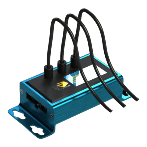
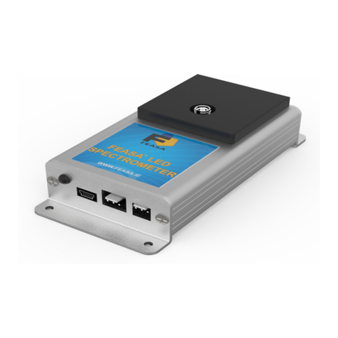
Feasa 10-IR User manual

FEASA LED ANALYSER
INFRA RED VERSION
User Manual for Infrared Models
Feasa Enterprises Ltd,
Holland Road,
National Te hnology Park,
Castletroy,
Limeri k,
Ireland.
www.feasa.ie
Email: [email protected]
Rev. 2.5 Infra Red Version
Date: Nov, 2021
1

FEASA LED ANALYSER
INFRA RED VERSION
About this Manual
Feasa operates a policy of continuous development. Feasa reserves the right to make changes
and improvements to any of the products described in this document without prior notice.
Feasa reserves the right to revise this document or withdraw it at any time without prior
notice.
This manual is written for Feasa Infrared LED nalysers. These nalysers have been designed
to test Infra-Red LED's only.
The 20-IR model will test up to 20 LED's, the 10-IR will test up to 10 LED's and the 3-IR will
test up to 3 LED's all with a Peak Wavelength range of 700nm - 950nm.
The 20-IRP model will test up to 20 LED's, the 10-IRP will test up to 10 LED's and the 3-IRP
will test up to 3 LED's with a Peak Wavelength range of 700nm - 900nm.
© Copyright 2005-2020 by Feasa Enterprises Ltd. All rights reserved. No parts of this
manual may be reprodu ed or retransmitted in any form or means, ele troni or
me hani al, in luding photo opying, re ording, or any other storage and retrieval
system without prior permission in writing from Feasa Enterprises Ltd. Every effort
has been made to ensure that the information in this manual is a urate. Feasa
Enterprises Limited is not responsible for printing or leri al errors.
2

FEASA LED ANALYSER
INFRA RED VERSION
Table of Contents
Important Safety Information...............................................................................................................5
Introduction..........................................................................................................................................6
Intensity................................................................................................................................................7
Setting Tolerance Limits for Peak Wavelength and Intensity...............................................................
Physical Layout....................................................................................................................................9
USB Port Control.................................................................................................................................9
Serial Port Control..............................................................................................................................10
Capture Commands............................................................................................................................11
Auto CAPTURE - Store LED Peak Wavelength and Intensity Data.............................................12
Manual CAPTURE# - Store LED Peak Wavelength and Intensity Data......................................13
Auto CAPTUREPWM - Capture PWM LED Peak Wavelength and Intensity.............................14
Manual CAPTURE#PWM@@ - Store LED Peak Wavelength and Intensity Data PWM LED's 15
Get Data Commands...........................................................................................................................16
Under Range Condition.................................................................................................................16
Over Range Condition...................................................................................................................16
getIR## - Return the Peak Wavelength and Intensity values.........................................................17
getWavelength## - Get the Peak Wavelength................................................................................1
getINTENSITY## - Get the Intensity............................................................................................19
getWI## - Get the Peak Wavelength & Intensity...........................................................................20
getSIGNALLEVEL## - Get the Relative Intensity in a percentage of the Range........................21
getIntGain - Get the Intensity Gain Factor....................................................................................22
getfactor - Get the exposure Factor................................................................................................23
getWAVELENGTHOFFSET@@ - Get the Peak Wavelength Offset...........................................24
getBAUD - Get the Baud Rate......................................................................................................25
getHW - Get the Hardware Version...............................................................................................26
getSTATUS - Get a summary of the Led Analyser details............................................................27
getSERIAL Get the Serial Number of the Analyser......................................................................2
getVERSION - Get the Firmware Version.....................................................................................29
General Set Commands ......................................................................................................................30
SetIntGain - Set the Intensity GainFactor......................................................................................31
SetFactor## - Set the Exposure Factor..........................................................................................32
set WAVELENGTHOFFSET@@±## - Set the wavelength Offset..............................................33
Daisy Chain Mode..............................................................................................................................35
Daisy Chain Communication.............................................................................................................37
help - Command Summary Listing................................................................................................50
Step-by-Step approach to Testing a LED...........................................................................................51
Effect of PWM on Intensity Testing...................................................................................................52
3

FEASA LED ANALYSER
INFRA RED VERSION
Step-by-Step approach to Testing a PWM LED.................................................................................53
Intensity Response..............................................................................................................................54
Command Summary...........................................................................................................................55
Specifications.....................................................................................................................................56
Warranty.............................................................................................................................................57
4

FEASA LED ANALYSER
INFRA RED VERSION
Important Safety Information
When using the Feasa -IR (Glass Fiber version) Eye protection must
be worn at all times when handling the Led nalyser or the Fibers.
Care should be taken when handling the bare ends of the Fibers
because they are composed of glass and may scratch unprotected
areas.
Infrared protection should be worn when working with Infrared
LED's and sources. Infrared light is invisible to the naked eye and
may cause damage to the eye or skin if exposed to high levels of
radiation.
Back to Index
5

FEASA LED ANALYSER
INFRA RED VERSION
Introdu tion
The Infrared Series of Feasa LED nalysers have been designed to test Infrared LED's only. The
nalyser is supplied in 3, 10, 20 channel versions with Plastic Fibers 700-900nm Peak
Wavelength range and Glass Fibers 700-950nm Peak Wavelength range.
Infrared LED's are invisible to the naked eye when lighted and these nalysers can be used to
test the Peak Wavelength and Relative Power (Intensity) of these LED's.
The Feasa 20-IR nalyser has 20* Glass Fiber-Optic Light Guides which are mounted
individually over the LEDs to be tested.
The Feasa 20-IRP nalyser has 20* Plastic Optical Fiber Light Guides which are mounted
individually over the LEDs to be tested.
Emitted Light from the LEDs is guided through these Fiber-Optic Light Guides to the nalyser
where the Peak Wavelength and Intensity are tested. The test results can then read out of
the nalyser through the Serial or USB Interfaces.
The USB Interface is 2.0 compatible and the Serial Interface is RS-232C compatible.
Peak Wavelength and Intensity values are output as SCII strings through the USB and Serial
Interfaces.
* There are 10 channel and 3 channel versions available.
Back to Index
6

FEASA LED ANALYSER
INFRA RED VERSION
Intensity
Intensity is a measure of the amount of light being emitted by the LED.
The nalyser tests the Intensity of each LED and outputs this value to the Test System. The
value is output as a number in the range 0-99999. The nalyser is calibrated to a fixed
standard and all measurements are relative. The Intensity output reading is NOT part of the
International System of Units and is not an absolute or traceable unit of colour measurement.
It is part of the Wavelength and Relative intensity (WI) system of describing colour.
The Infra Red nalyser is set to measure Intensity on a Linear scale.
Factors that influence Intensity Measurement:-
The position of the Fiber in relation to the LED.
Offset from the Optical Centre of the LED.
The Gap between the end of the Fiber Light Guide and LED to be measured.
The condition of the Fiber end. It must be kept clean with a 90º Cleave.
Is the LED Static or Flashing ?
External Influences – Other LEDs in close proximity, mbient Lighting.
There are 6 capture ranges each with an intensity output range of 0 to 99,999. Feasa
recommends that the UUT readings should be in the 50K to 90K range for the best
stability.
Figure . Relative Intensity Response
Back to Index
7
0 100 200 300 400 500 600 700 800 900
0
10000
20000
30000
40000
50000
60000
70000
80000
90000
Linear Intensity
Relative Intensity

FEASA LED ANALYSER
INFRA RED VERSION
Setting Toleran e Limits for Peak Wavelength and Intensity
The test procedure requires the user to set the Pass/Fail limits for Peak Wavelength and
Intensity for each LED which then become the standard against which LEDs to be tested are
compared.
The Pass/Fail limits for Peak Wavelength are chosen, in conjunction with manufacturer’s
specifications, from measurements taken from a sample number of typical LEDs.
Sample Peak Wavelength Pass/Fail Limits
LED Minimum Maximum
830 820 840
880 870 890
900 891 910
930 910 950
Figure 2.
The Pass/Fail limits for intensity are chosen from the average intensity values from a number
of sample LEDs.
Sample Intensity Pass/Fail Limits on a single apture range. Eg C2
Intensity Value Upper Limit Lower Limit Comments
1250 1500 1000 Dim LED
25000 28000 22000 verage LED
60000 64000 56000 Bright LED
Figure 3.
Back to Index
8

FEASA LED ANALYSER
INFRA RED VERSION
Physi al Layout
Figure 4a (Front Panel).
Figure 4b (Rear Panel).
This shows the layout of the Connectors viewed from the edge of the board.
Figure 4a shows the physical layout of the Feasa x-IR / IRP nalyser Front Panels.
Figure 4b shows the physical layout of the Feasa x-IR / IRP nalyser Rear Panels.
These units are enclosed in a Red luminium Case. The Serial port is a 3 pin connector with
the cables supplied and the USB connector is the mini usb again the cable is supplied with the
unit.
Please refer to the Fixturing Guidelines Manual for onne tor pin out details.
USB Port Control
Connect the LED nalyser to the PC using the supplied USB cable.
Power is supplied through the USB Cable so there is no need to plug in the Power cable.
The installed Software Driver will configure the USB Port automatically.
The USB Port is configured as a Virtual Com Port and will be designated a name such as COM5,
COM6, etc.
Back to Index
9
1
2
3
D_IN
1
2
3
D_OUT
GND
5V
POWER SUPPLY

FEASA LED ANALYSER
INFRA RED VERSION
Serial Port Control
For serial communications the LED nalyser must be connected from the 3-pin Serial
Connector to the PC or Controller using the supplied serial cable (L -SER-02).
5VDC @ 200m must be supplied to the 2-pin Power Connector using the Power Cable
provided (L -PWR-01). See figure 7. Prolonged Voltages > 7V can damage the Analyser.
The Green LED should turn on to indicate the nalyser is ready for use.
The default serial communications settings are 57,600 Baud, 8 Data bits, 1 Stop bit and
No Parity.
The baud rate can be changed to any of the following:- 9600, 19200, 38400, 57600, 115200.
See the setbaud command for more details.
Serial Connector (RS232C)
Pin Signal Pin on 9-Pin
D-type
1 Tx from LED nalyser 2
2 Rx from LED nalyser 3
3 GND 5
Power Connector
Pin No Signal
1 Power (5V DC)
2 GND
Figure 5.
Back to Index
10

FEASA LED ANALYSER
INFRA RED VERSION
Capture Commands
The Capture commands are used to capture the Peak Wavelength and Intensity of the LED's to
be tested and store the results in the memory of the nalyser.
These results can be read out later using the GET DATA commands.
Commands are transmitted and received using SCII characters and are ase-insensitive.
ll commands must be terminated with a <CR> or <LF> character.
There are two Programs on the supplied CD that can be used to send commands to the
nalyser:- Feasa LED Analyser Terminal and the Feasa LED Analyser Test Programs.
The Feasa LED Analyser Terminal is a command line program that can be used to send
commands and receive results from the nalyser. This allows the user to view the command
codes and responses from the nalyser.
The Feasa LED Analyser Test Program allows the User to test all the LED's together. Pass
and Fail limits can be set and results can be printed and logged.
lternately, the User may generate a customised Program that sends commands and receives
data through the virtual USB Com Port.
Back to Index
11

FEASA LED ANALYSER
INFRA RED VERSION
Capture Mode
Auto CAPTURE - Store LED Peak Wavelength and Intensity Data
Transmit Receive
Capture
OK
OK
Description
This command instructs the LED nalyser to capture and store the Peak Wavelength and
Intensity of all the LED's positioned under the fibers. The nalyser automatically determines
the correct settings to capture the LED data. In the case of a 20 channel unit the data for all
20 LED's is captured simultaneously and stored in internal memory of the LED nalyser. The
data is stored until the power is removed or another apture command is issued. When
completed the nalyser will transmit the character OK on the receive line to the transmitting
device (i.e. the PC).
This command uses a wide Intensity range to be able to test dim and bright LED's
simultaneously. However, if the LED's to be tested are of similar Intensity then better results
may be obtained by using the Capture# command described on the next page.
Example:
The PC transmits apture to the LED nalyser and the LED nalyser sends OK to the PC to
acknowledge that the command is completed.
apture
OK
Back to Index
12

FEASA LED ANALYSER
INFRA RED VERSION
Capture Mode
Manual CAPTURE# - Store LED Peak Wavelength and Intensity Data
Transmit Receive
CAPTURE#
C#
OK
OK
W ere:
# represents the ranges 1, 2, 3, 4, 5.
The LED brightness level for each range is as follows:-
Range 1 = Low
Range 2 = Medium
Range 3 = High
Range 4 = Super
Range 5 = Ultra
Description
This command uses a pre-selected exposure time designated Range1, Range2 etc. For low
light or dim LED's use Range 1 and for brighter LED's use higher ranges. The higher ranges
lead to faster test times because the exposure time is shorter.
This command instructs the LED nalyser to read and store the Peak Wavelength and Intensity
of all the LED's positioned under the fibers using a fixed range.
The range setting must be specified. The data is stored until the power is removed or another
apture command is issued. When completed the nalyser will transmit the character OK on
the receive line to the transmitting device (i.e. the PC).
Example:
The PC transmits apture to the LED nalyser and the LED nalyser sends OK to the PC to
acknowledge that the command is completed.
apture2
OK
There are 5 manual apture ranges ea h with an intensity output range of 0 to
99,999. Feasa re ommends that the UUT readings should be in the 55K to 85K range
for the best stability.
Back to Index
13

FEASA LED ANALYSER
INFRA RED VERSION
Capture Mode
Auto CAPTUREPWM - Capture PWM LED Peak Wavelength and
Intensity
Transmit Receive
CAPTUREPWM
CPWM
OK
OK
Description
Pulse-Width-Modulated(PWM) LED's are switched on and off rapidly to save power and to
control Intensity. The nalyser automatically determines the correct settings required to
execute the test.
This command uses the auto-ranging feature and a pre-set averaging factor to capture the
LED data. This command is useful if it is required to test very dim and very bright PWM LED's
together.
The command instructs the LED nalyser to read and store the Peak Wavelength and Intensity
of all the LED's positioned under the fibers. The data is stored until the power is removed or
another apture command is issued. When completed the nalyser will transmit the
character OK on the receive line to the transmitting device (i.e. the PC).
Example:
The PC transmits apturepwm to the LED nalyser. The nalyser sends OK to the PC to
acknowledge that the command is completed.
apturepwm
OK
Back to Index
14

FEASA LED ANALYSER
INFRA RED VERSION
Capture Mode
Manual CAPTURE#PWM@@ - Store LED Peak Wavelength and Intensity
Data PWM LED's
Transmit Receive
CAPTURE#PWM@@
C#PWM@@
OK
OK
W ere:
# represents the exposure Range 1 – 5.
@@ represents an averaging factor in the range 1 - 15.
Description
This command allows the User to specify the exposure range and an averaging factor when
testing PWM LED's. Select the exposure range (1-5) to matc t e Intensity of t e LED's. The
nalyser tests these LED's by taking a number of readings and averaging the results. larger
factor will lead to more stable results. The averaging factor is a number in the range 1-15.
This command instructs the LED nalyser to read and store the Peak Wavelength and Intensity
of all the LED's positioned under the fibers. The data is stored until the power is removed or
another apture command is issued. When completed the nalyser will transmit the
character OK on the receive line to the transmitting device (i.e. the PC).
apture1pwm05
OK
There are 5 manual apture ranges ea h with an intensity output range of 0 to
99,999. Feasa re ommends that the UUT readings should be in the 55K to 85K range
for the best stability.
Back to Index
15

FEASA LED ANALYSER
INFRA RED VERSION
Get Data Commands
The get data commands are used to read out the Peak Wavelength and Intensity data stored
by the capture commands.
The data from the last capture command remains in memory until a new capture command is
issued or the power is removed from the nalyser.
Commands are transmitted and received using SCII characters and are NOT ase-sensitive.
ll commands must be terminated with a <CR> and <LF> characters.
When the nalyser sends a response each line is terminated with a <CR> and <LF>
characters.
Under Range Condition
n under range condition will occur when insufficient light from the LED reaches the sensor for
the range selected. This will be indicated by 0000 00000 for Peak Wavelength and
Intensity.
If this condition occurs select the next lower range and test again.
Over Range Condition
n over range condition will occur when too much light from the LED reaches the sensor for
the range selected by the switch. This will be indicated by 0000 99999 for Peak Wavelength
and Intensity.
If this condition occurs select the next higher range and test again.
Back to Index
16

FEASA LED ANALYSER
INFRA RED VERSION
Get Data Mode
getIR## - Return the Peak Wavelength and Intensity values
Transmit Receive
Getir##
getirall
wwww iiiii
W ere:
## represents the Fiber Number and is a number in the range 01 – 20.
www represents the Peak Wavelength value
iiiii represents the Intensity value
Description
This command is used to return the Peak Wavelength and Intensity values for the LED under
the Fiber number ##.
This command should be preceded by a apture command to ensure valid LED data is stored
in the memory of the LED nalyser. The data for each LED can only be read out one-at-the-
time, in any order. Note: it is important for the PC to use 01, 02, 03, etc to indicate Fibers 1,
2 and 3, etc.
Example:
The PC transmits getir01 to the LED nalyser to instruct it to send the stored Peak
Wavelength and Intensity data for the LED positioned under Fiber No 1. The LED nalyser will
return a string wwww iiiii to the PC.
getir01
0850 68123
Back to Index
17

FEASA LED ANALYSER
INFRA RED VERSION
Get Data Mode
getWavelength## - Get the Peak Wavelength
Transmit Receive
Getwavelength##
getwavelengthall
XXX
W ere:
## represents the Fiber Number and is a number in the range 1 – 20.
xxx represents the peak wavelength of the LED in nanometers.
Description
This command is used to get the value of the Peak Wavelength for the LED under the Fiber
number ##.
This command should be preceded by the apture C command to ensure valid LED data is
stored in the memory of the LED nalyser. The C1-C5 commands are available but are not as
accurate. The data for each LED can only be read out one-at-the-time, in any order.
Example:
The PC transmits getwavelength01 to the LED nalyser to instruct it to send the stored
peak wavelength for the LED positioned under Fiber No 1. The LED nalyser will return a
string xxx to the PC.
getwavelength01
513
Back to Index
18

FEASA LED ANALYSER
INFRA RED VERSION
Get Data Mode
getINTENSITY## - Get the Intensity
Transmit Receive
Getintensity##
getintensityall
IIIII
W ere:
## represents the Fiber Number and is a number in the range 01 – 20.
IIIII represents the Intensity value.
Description
This command is used to get the Intensity value for the LED under the Fiber number ##.
This command should be preceded by a apture command to ensure valid LED data is stored
in the memory of the LED nalyser. The data for each LED can only be read out one-at-the-
time, in any order. Note: it is important for the PC to use 01, 02, 03, etc to indicate Fibers 1,
2 and 3, etc.
Example:
The PC transmits getintensity01 to the LED nalyser to instruct it to send the stored XY
Chromaticity data for the LED positioned under Fiber No 1. The LED nalyser will return a
string IIIII to the PC.
getintensity01
06734
Back to Index
19

FEASA LED ANALYSER
INFRA RED VERSION
Get Data Mode
getWI## - Get the Peak Wavelength & Intensity
Transmit Receive
Getwi##
getwiall
XXX YYYYY
W ere:
## represents the Fiber Number and is a number in the range 1 – 20.
xxx represents the peak wavelength of the LED in nanometers.
YYYYY represents the intensity of the LED.
Description
This command is used to get the value of the Peak Wavelength for the LED under the Fiber
number ##.
This command should be preceded by the apture C command to ensure valid LED data is
stored in the memory of the LED nalyser. The C1-C5 commands are available but are not as
accurate. The data for each LED can only be read out one-at-the-time, in any order.
Example:
The PC transmits getwi01 to the LED nalyser to instruct it to send the stored peak
wavelength & Intensity for the LED positioned under Fiber No 1. The LED nalyser will return
a string xxx yyyyy to the PC.
getwi01
513 12345
Back to Index
20
This manual suits for next models
3
Table of contents
Other Feasa Measuring Instrument manuals
Popular Measuring Instrument manuals by other brands
Varian
Varian CP-4900 Micro-GC Firmware update manual
Hohner Automaticos
Hohner Automaticos VI96 Operation manual

ViroGates
ViroGates suPARnostic GENSPEED R2 manual

Heyuan Intelligence
Heyuan Intelligence DZ81-MSU7C user manual
Hanna Instruments
Hanna Instruments DiST HI 98302 quick start guide

Agilent Technologies
Agilent Technologies E8361C Service note
