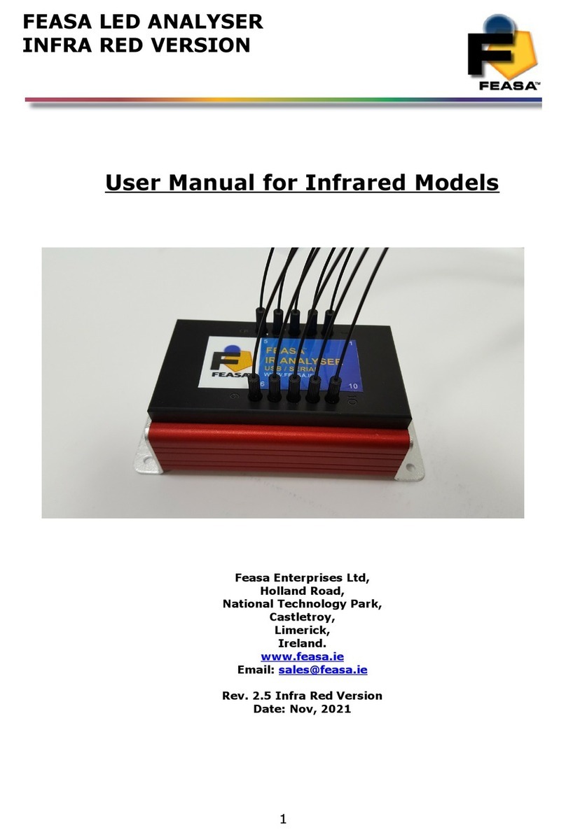
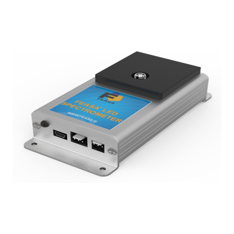
Feasa Low Light LED Analyser User manual

FEASA LED ANALYSER LOW LIGHT
FUNCTIONAL VERSION
User Manual for Low Li ht LED Analyser
Feasa Enterprises Ltd,
Holland Road,
National Technolo y Park,
Castletroy,
Limerick,
Ireland.
www.feasa.ie
Email: [email protected]
Rev. 3.0
Date: October 2021
1

FEASA LED ANALYSER LOW LIGHT
FUNCTIONAL VERSION
About this Manual
Feasa operates a policy of continuous development. Feasa reserves the right to make changes
and improvements to any of the products described in this document without prior notice.
Feasa reserves the right to revise this document or withdraw it at any time without prior
notice.
This manual is written for models Feasa Low Light Led Analysers. The model numbers are
Feasa 3-A 5-A 6-A and 10-A.
The Feasa 10-A model is a 10 channel unit which will test up to 10 LEDs while the Feasa 3-A is
a 3 channel unit testing up to 3 LEDs.
The interface on these units is USB or Serial.
© Copyri ht 2005-2021 by Feasa Enterprises Ltd. All ri hts reserved. No parts of this
manual may be reproduced or retransmitted in any form or means, electronic or
mechanical, includin photocopyin , recordin , or any other stora e and retrieval
system without prior permission in writin from Feasa Enterprises Ltd. Every effort
has been made to ensure that the information in this manual is accurate. Feasa
Enterprises Limited is not responsible for printin or clerical errors.
2

FEASA LED ANALYSER LOW LIGHT
FUNCTIONAL VERSION
Table of Contents
Introduction..........................................................................................................................................5
IMPORTANT INFORMATION for Programmers...............................................................................6
Colour and Saturation...........................................................................................................................7
Intensit ................................................................................................................................................9
White LED's.......................................................................................................................................10
Setting Tolerance Limits for Color and Intensit ...............................................................................11
Ph sical La out..................................................................................................................................12
USB Port Control...............................................................................................................................12
Serial Port Control..............................................................................................................................13
Capture Commands........................................................................................................................15
AUTO CAPTURE - Store LED Data .......................................................................................16
MANUAL CAPTURE - Store LED Data for a specific range.................................................17
Get Data Commands...........................................................................................................................18
Under Range Condition.................................................................................................................18
Over Range Condition...................................................................................................................18
getRGBI## - Get RGB and Intensit for a LED.......................................................................19
getHSI## - Get Hue, Saturation and Intensit ..........................................................................20
getx ## - Return the x Chromaticit values...........................................................................21
getuv## - Return the u'v' Chromaticit values..........................................................................22
getwavelength## - Get the Dominant Wavelength...................................................................23
getWI## - Get the Dominant Wavelength & Intensit ..............................................................24
getcct## - Get the Correlated Colour Temperature...................................................................25
getintensit ## - Get the Intensit ..............................................................................................26
getABSINT@@ Get the Absolute Intensit Value of the Led under test.................................27
getfactor - Get the exposure Factor...........................................................................................28
getABSINT@@ Get the Absolute Intensit Value of the Led under test.................................29
getaverage - Get the number of Captures to Average...............................................................30
getBAUD - Get the Baud Rate..................................................................................................31
getHW - Get the Hardware Version..........................................................................................32
getSTATUS - Get a summar of the Led Anal ser details........................................................33
getSERIAL Get the Serial Number of the Anal ser.................................................................34
getVERSION - Get the Firmware Version................................................................................35
EOT - End of Transmission Character......................................................................................36
S et Data Mode ....................................................................................................................................37
General Set Commands.................................................................................................................37
set/putFACTOR## - Set the Exposure Factor...........................................................................38
setaverage - Set the number of Captures to Average.................................................................39
setBAUD - Change the baud rate..............................................................................................40
User Calibration Mode.......................................................................................................................41
Introduction:..............................................................................................................................41
UserCal Manual Procedure:......................................................................................................42
set/putINTGAIN - Set the Intensit GainFactor.......................................................................43
getINTGAIN## - Get the Intensit Gain Factor.......................................................................44
3

FEASA LED ANALYSER LOW LIGHT
FUNCTIONAL VERSION
set/putXOFFSET##0.xxx - Set the x Chromaticit Offset.......................................................45
set/putYOFFSET##0.xxx - Set the x Chromaticit Offset.......................................................46
getXOFFSET## - Return the x Chromaticit offset.................................................................47
getYOFFSET## - Return the Chromaticit offset.................................................................48
set/putWAVELENGTHOFFSET@@±## - Set the wavelength Offset....................................49
getWAVELENGTHOFFSET@@ - Get the Dominant Wavelength Offset..............................50
set/putABSINTMULT@@ - Set the x Chromaticit Offset.....................................................51
getABSINTMULT@@ Get the Absolute Intensit Correction Factor of the Led under test...52
setCALIBRATION## - Select the Calibration Set to use.........................................................53
SetCalibrationDateddmm - Set the user Cal Date.............................................................54
getcalibrationdate Get the Calibration Date set b the user......................................................55
HELP - Command Summar Listing........................................................................................56
Dais Chain Mode..............................................................................................................................57
Dais Chain USB Wiring Method:...........................................................................................57
Dais Chain Communication.............................................................................................................59
Dais Chain Baudrate:..............................................................................................................59
Dais Chain Identification:.......................................................................................................59
BusFree - Deactivate an active Anal sers...............................................................................60
BusGet#### - Activate a LED Anal ser...................................................................................61
BusC - Initiate Capture for all LED Anal ser's.........................................................................62
BusC# - Initiate Capture for all LED Anal ser's.......................................................................63
BusCE#### - Poll each LED Anal ser to verif a capture is complete....................................64
Ports Description and Wiring....................................................................................................65
Dais Chain Pinout...................................................................................................................66
Step-b -Step method for Dais Chaining.................................................................................67
Example....................................................................................................................................69
Step-b -Step approach to Testing a LED...........................................................................................71
Command Summar ...........................................................................................................................72
Back to Index......................................................................................................................................73
Specifications.....................................................................................................................................74
Warranty.............................................................................................................................................75
4

FEASA LED ANALYSER LOW LIGHT
FUNCTIONAL VERSION
Introduction
The Feasa Low Light Analyser is an instrument that tests the Color and Intensity of Light
Emitting Diodes (LEDs) in a Test Process. It has been specifically designed to test Leds in low
light situations such as backlit Switches and Panels. The Analyser has up to 10* flexible
Fiber-Optic Light Guides which are mounted individually over the LEDs to be tested.
Emitted Light from the LEDs is guided through these Fiber-Optic Light Guides to the Analyser
where the raw data is stored. The raw data can then be read out of the Analyser through the
Serial or USB Interfaces.
The USB Interface is 2.0 compatible.
The Serial Interface is a 3-Pin Connector with a 3 pin to 9 pin dtype cable (supplied)
compatible with the RS-232C ports on machines.
All colors are derived from the three primary colors Red Green and Blue (RGB). The RGB
values are used to identify different color LEDs.
The raw data from the Led under test is stored on the Led Analyser and output in different
formats as required through the Serial and ICT interfaces.
* Other options include 3 5 & 6
Back to Index
5

FEASA LED ANALYSER LOW LIGHT
FUNCTIONAL VERSION
IMPORTANT INFORMATION for Programmers
set / put Commands
The Set / Put commands are used to adjust various settings in the LED Analyser such as
Intensity Exposure and offsets.
The Set commands are written to the on-board Flash.
These settings remain programmed in the Analyser even when the power is removed.
The Led Analyser has a capacity limit of approximately 100 000 writes to the flash.
Use the Set command only to store relevant information on the Led Analyser. Please refrain
from using Set commands in your high volume production programs as this constant writing to
the Flash will eventually corrupt the Led Analyser. Use the Put command instead.
The Put commands are written to the on-board RAM.
These settings will NOT remain programmed in the Analyser after the power is removed.
Use the Put command as often as you need in your program. This will prolong the life of the
Led Analyser particularly in high volume testing environment.
Commands are transmitted and received using ASCII characters and are case-insensitive.
All commands must be terminated with a <CR> or <LF> character.
Back to Index
6

FEASA LED ANALYSER LOW LIGHT
FUNCTIONAL VERSION
Colour and Saturation
Figure 1: Hue (Color) Wheel
RED = 0º
GREEN = 120º
BLUE = 240º
Colours can represented by a 360° degree circular Colour wheel. The three Primary RGB values
can also be represented as a single value called Hue. Hue is a measured location on a Colour
wheel and is expressed in degrees. For example Red will have a Hue value near 0° Green
will have a Hue value near 120° and Blue will have a value near 240°.
A pure Colour will be represented on the Colour wheel as a point near the outer edge. White
will be represented by a point near the center of the wheel. The degree of whiteness in a LED
will affect its position on the wheel – the greater the amount of white the closer it will be to the
center.
The Feasa Led Analyser output of aturation is NOT part of the International System of Units.
and is not an absolute or traceable unit of colour measurement. It is part of the Hue Saturation
and Relative intensity (HSI) system of describing colour. The degree of whiteness emitted by
the LED is represented by the term aturation. A Saturation value of 0% represents pure
White. A Saturation value of 95 - 100% represents a pure Colour such as Red Blue Green
etc. It is a relative output much the same as the Relative Intensity output and is used to
compare similarly coloured LEDs under test. The Saturation values are calculated within the
Feasa Led Analyser for each channel of the LED Analyser relative to the LED under test.
There is a consistency in the Saturation readings between all Feasa Led Analysers for LEDs of
a similar colour in a similarly constructed fixture.
Usually the user must determine the Hue and Saturation values by testing a number of LED's
and recording the results.
Back to Index
7

FEASA LED ANALYSER LOW LIGHT
FUNCTIONAL VERSION
The RGB and Hue values in Figure 2 show how different Colour LEDs can be identified.
LED R G B HUE SATURATION
Red 253 1 1 0 100%
Green 24 208 23 120 89%
Blue 2 13 240 238 99%
Yellow 76 171 8 95 96%
Orange 224 28 2 7 99%
White 71 72 112 See Page 10 37%
Figure 2.
The RGB or Hue values are used to identify different Colour LEDs.
Every LED tested by the LED Analyser will have a set of RGB values generated for analysis.
These values are converted automatically to Hue and Saturation (whiteness) and can be read
out through the Serial or USB ports.
Back to Index
8

FEASA LED ANALYSER LOW LIGHT
FUNCTIONAL VERSION
Intensity
Intensity is a measure of the amount of light being emitted by the LED. The Analyser tests the
Intensity of each LED and outputs this value to the Test System. The value is output as a
number in the range 0-99 999. The Analyser is calibrated to a fixed standard and all
measurements are relative.
The Low Light Analyser measures Intensity of the LED on a Linear scale.
Factors that influence Intensity Measurement:
The position of the Fiber in relation to the LED.
Offset from the Optical Centre of the LED.
The Gap between the end of the Fiber Light Guide and LED to be measured.
The condition of the Fiber end. It must be kept clean with a 90º Cleave.
Is the LED Static or Flashing ?
External Influences – Other LEDs in close proximity Ambient Lighting.
Is an Optical Head being used.
Figure 3. Relative Intensity for the LED Analyser in LINEAR mode
Back to Index
9
0 10000 20000 30000 40000 50000 60000 70000 80000
0
10000
20000
30000
40000
50000
60000
70000
80000
Relative Intensity LINEAR mode for Standard Led Analyser

FEASA LED ANALYSER LOW LIGHT
FUNCTIONAL VERSION
White LED's
White LED's must be treated differently to coloured LED's when being tested. White is not a
colour – it is a mix of all other colours. The three Primary colours Red Green and Blue will be
mixed in approximately equal proportions to display a White colour. The Saturation values
must be used when testing White LED's. The Saturation is a value between 0% and 100%. A
value of 0% indicates a pure white and a value of 100% indicates a pure Colour.
In reality the Saturation value of white LED's vary significantly with values of 30% being
typical. Remember the Saturation value is an indication of how white the LED is.
The correct values must be determined experimentally with the particular LED's to be tested.
Most LED manufacturers will specify their White LED's using Chromaticity co-ordinates xy. This
is a two-dimensional Chart with x on the horizontal axis and y on the vertical axis. The range
of x and y lies between 0 and 1.
y
x
Figure 4. CIE 1931 Chromaticity Co-Ordinates
White LED's will have approximate co-ordinates of 0.33 0.33. This may vary depending on the
manufacturer of the LED where some LED's will have a Blue tint (cool white) and the other
LED's will have a Red tint (Warm White).
Back to Index
10

FEASA LED ANALYSER LOW LIGHT
FUNCTIONAL VERSION
Settin Tolerance Limits for Color and Intensity
The test procedure requires the user to set the Pass/Fail limits for Colour and Intensity for
each LED which then becomes the standard against which LEDs to be tested are compared.
The Pass/Fail limits for Colour are chosen in conjunction with manufacturer’s specifications
from measurements taken from a sample number of typical LEDs.
Because Hue is expressed as a single number it is more convenient to set the limits for the
colour in terms of their Hue value.
Sample Hue Pass/Fail Limits
LED Minimum Maximum
Red 0 2
Green 110 130
Blue 220 250
Amber 2 10
Yellow 60 80
Orange 10 20
Figure 5a.
The Saturation value must be taken into account when testing White LED's. The Saturation is
a value between 0% and 100%. A pure white will have a value close to 0% while a pure
colour will have a value close to 100%.
The Pass/Fail limits for intensity are chosen from the average intensity values from a number
of sample LEDs.
Sample Intensity Pass/Fail Limits
Intensity Value Upper Limit Lower Limit Comments
125 150 100 Dim LED
25000 28000 22000 Average LED
60000 64000 56000 Bright LED
Figure 5b.
Note:- the Relative Intensity Value will depend on the Range selected.
Note:- Feasa recommends selecting a Capture Range to achieve Relative Intensity Reading of
55K to 85K for the best results.
Back to Index
11

FEASA LED ANALYSER LOW LIGHT
FUNCTIONAL VERSION
Physical Layout
Figure 6a (Front Panel).
Figure 6b (Rear Panel).
This shows the layout of the Connectors viewed from the edge of the board.
Fi ure 6a shows the physical layout of the Feasa Low Light Analyser Front Panels.
Fi ure 6b shows the physical layout of the Feasa Low Light Analyser Rear Panels.
Please refer to the fixturin Guidelines Manual for connector pin out details.
USB Port Control
Connect the LED Analyser to the PC using the supplied USB cable.
Power is supplied through the USB Cable so there is no need to plug in the Power cable.
The installed Software Driver will configure the USB Port automatically.
The USB Port is configured as a Virtual Com Port and will be designated a name such as COM5
COM6 etc.
Back to Index
12
1
2
3
D_IN
1
2
3
D_OUT
GND5V
POWER SUPPLY

FEASA LED ANALYSER LOW LIGHT
FUNCTIONAL VERSION
Serial Port Control
For serial communications the LED Analyser must be connected from the 3-pin Serial
Connector to the PC or Controller using the supplied serial cable.
5V DC @ 200mA must be supplied to the 2-pin Power Connector using the Power Cable
provided. (LA-PWR-01). See figure 7. Prolonged Voltages > 7V can damage the
Analyser.
The Green LED should turn on to indicate the Analyser is ready for use.
The default serial communications settings are 57,600 Baud, 8 Data bits, 1 Stop bit and
No Parity.
The baud rate can be changed to any of the following:- 9600 19200 38400 57600 115200.
These can be selected using the setbaud command.
erial Connector (R 232C)
Pin ignal Pin on 9-
Pin D-type
1 Tx from LED Analyser 2
2 Rx from LED Analyser 3
3 GND 5
Power Connector
Pin No ignal
1 Power (5V DC)
2 GND
Figure 7.
Back to Index
13

FEASA LED ANALYSER LOW LIGHT
FUNCTIONAL VERSION
Capture Commands
The Capture commands are used to capture the parameters (color intensity xy uv
wavelength cct) of the LED's to be tested and store the results in the memory of the Analyser.
These results can be read out later using the GET DATA commands.
Commands are transmitted and received using ASCII characters and are NOT case-sensitive.
All commands must be terminated with a <CR> or <LF> character. All responses from the
Led Analyser are also terminated with <CR> <LF>
The Terminal Pro ram supplied on the CD is used to send/receive commands to/from the
Analyser. This program is also available as a drop down function of the USER and Test
Software programs.
The Feasa LED Analyser User Program is a graphical tool that can be used to send
commands and receive results from the Analyser. It allows one LED to be tested at a time.
This Program also allows a Terminal Window to be opened so that the User can type the
commands directly and send them to the Analyser. The responses from the Analyser can be
observed in the Window.
The Feasa LED Analyser Test Program allows the User to test all the LED's together. Pass
and Fail limits can be set and results can be printed and logged.
Alternately the User may generate a customised Program that sends commands and receives
data through the virtual USB Com Port.
Back to Index
14

FEASA LED ANALYSER LOW LIGHT
FUNCTIONAL VERSION
Capture Mode
AUTO CAPTURE - Store LED Data
Transmit Receive
Capture
c
OK
OK
Description
This Auto Range Capture instructs the LED Analyser to capture and store the data of all the
LED's positioned under the fibers. The Analyser automatically determines the correct settings
to capture the LED data based on the Intensity. In the case of a 10 channel unit the data for
all 10 LED's are captured simultaneously and stored in internal memory of the LED Analyser.
The data is stored until the power is removed or another capture command is issued. When
completed the Analyser will transmit the character OK on the receive line to the transmitting
device (i.e. the PC).
This command uses a wide Intensity range to be able to test dim and bright LED's
simultaneously. However if the LED's to be tested are of similar Intensity then better results
will be obtained by using the Capture command described on the next page.
Example:
The PC transmits capture to the LED Analyser and the LED Analyser sends OK to the PC to
acknowledge that the command is completed.
Capture
or
c
OK
Back to Index
15

FEASA LED ANALYSER LOW LIGHT
FUNCTIONAL VERSION
Capture Mode
MANUAL CAPTURE - Store LED Data for a specific ran e
Transmit Receive
Capture#
c#
OK
OK
Where:
# represents the ranges 1 2 3 4 5.
The LED brightness level for each range is as follows:-
Range 1 = Low
Range 2 = Medium
Range 3 = High
Range 4 = Super
Range 5 = Ultra
Description
This command uses a pre-selected exposure time designated Range1 Range2 etc. For low
light or dim LED's use Range 1 and for brighter LED's use higher ranges. The higher ranges
lead to faster test times because the exposure time is shorter.
This command instructs the LED Analyser to read and store the Color and Intensity of all the
LED's positioned under the fibers using a fixed range.
The range setting must be specified. The data is stored until the power is removed or another
capture command is issued. When completed the Analyser will transmit the character OK on
the receive line to the transmitting device (i.e. the PC).
Example:
The PC transmits capture to the LED Analyser and the LED Analyser sends OK to the PC to
acknowledge that the command is completed.
Capture2
or
c2
OK
There are 5 manual capture ran es each with an intensity output ran e of 0 to
99,999. Feasa recommends that the UUT readin s should be in the 55K to 85K ran e
for the best stability.
Back to Index
16

FEASA LED ANALYSER LOW LIGHT
FUNCTIONAL VERSION
Capture Mode
Get Data Commands
The get data commands are used to read out the Color Saturation and Intensity data stored
by the capture commands.
The data from the last capture command remains in memory until a new capture command is
issued or the power is removed from the Analyser.
Commands are transmitted and received using ASCII characters and are NOT case-sensitive.
All commands must be terminated with a <CR> or <LF> character.
Under Ran e Condition
An under range condition will occur when insufficient light from the LED reaches the sensor for
the range selected. This will be indicated by 999.99 999 00000 for HSI, 000 000 000
00000 for RGBI and 0.0000 0.0000 for xy and uv.
If this condition occurs select the next lower range and test again.
Over Ran e Condition
An over range condition will occur when too much light from the LED reaches the sensor for
the range selected by the switch. This will be indicated by 999.99 999 99999 for HSI,
255 255 255 99999 for RGBI and 0.0000 0.0000 for xy and uv.
If this condition occurs select the next hi her range and test again.
Back to Index
17

FEASA LED ANALYSER LOW LIGHT
FUNCTIONAL VERSION
Get Data Mode
getRGBI## - Get RGB and Intensity for a L D
Transmit Receive
etr bi##
etrb iall
Rrr bbb iiiii
Where:
## represents the Fiber Number and is a number in the range 01 – 10.
rrr , and bbb are the red, reen and blue components of the LED color.
These values are normalized and are in the range 0 – 255.
iiiii represents the intensity value of the LED under Fiber xx. This 5-digit number is in the
range 0000 – 99999. 0000 represents no Intensity or under range(i.e. the LED is off) and
99999 will represent over range or the LED is too bright.
Description
This command instructs the LED Analyser to return RGB and Intensity data for fiber ## (01-
10) in format rrr bbb iiiii where rrr and bbb are the red green and blue
components of the color. The iiiii value indicates the intensity value.
This command should be preceded by a capture command to ensure valid LED data is stored
in the memory of the LED Analyser. The data for each LED can only be read out one-at-the-
time in any order. Note: it is important for the PC to use 01 02 03 etc to indicate Fibers
1 2 and 3 etc.
Alternatively use the getrgbiall command to read back the LED data for all 10 leds in
one command.
Example:
The PC transmits etr bi05 to the LED Analyser to instruct it to send the stored Color and
Intensity data for the LED positioned under Fiber No 5. The LED Analyser will return a string
rrr bbb iiiii to the PC.
etr bi05
006 230 018 06383
Back to Index
18

FEASA LED ANALYSER LOW LIGHT
FUNCTIONAL VERSION
Get Data Mode
getHSI## - Get Hue, Saturation and Intensity
Transmit Receive
ethsi##
ethsiall
Hhh.hh sss iiiii
Where:
## represents the Fiber Number and is a number in the range 01 – 10.
all represents the 10 Fibers in a Feasa 10A or 3 Fibers in a 3A.
hhh.hh represents the Hue (color) and is a number in the range 0.00 – 360.00.
sss represents the Saturation (whiteness) and is a number in the range 0–100.
iiiii represents the intensity value of the LED under fiber ##. This 5-digit number is in the
range 0000 – 99999. 0000 represents no Intensity or under range(i.e. the LED is off) and
99999 will represent over range or the LED is too bright.
Description
This command instructs the LED Analyser to return Hue Saturation and Intensity data for
fiber ## (01-10) in format hhh.hh sss iiiii where hhh.hh represents the Hue(Color) sss
represents the Saturation(whiteness) of the LED under Fiber ##. The iiiii value indicates the
intensity value.
This command should be preceded by a capture command to ensure valid LED data is stored
in the memory of the LED Analyser. The data for each LED can only be read out one-at-the-
time in any order. Note: it is important for the PC to use 01 02 03 etc to indicate Fibers 1
2 and 3 etc.
Alternatively use the gethsiall command to read back the LED data for all 10 leds in
one command.
Example:
The PC transmits ethsi05 to the LED Analyser to instruct it to send the stored Color and
Intensity data for the LED positioned under Fiber No 5. The LED Analyser will return a string
hhh.hh sss iiiii to the PC.
ethsi05
123.47 098 06383
Back to Index
19

FEASA LED ANALYSER LOW LIGHT
FUNCTIONAL VERSION
Get Data Mode
getxy## - Return the xy Chromaticity values
Transmit Receive
etxy##
etxyall
0.xxxx 0.yyyy
Where:
## represents the Fiber Number and is a number in the range 01 – 10.
all represents the 10 Fibers in a Feasa 10A or 3 Fibers in a 3A.
0.xxxx represents the x Chromaticity value
0.yyyy represents the y Chromaticity value
Description
This command is used to return the xy Chromaticity value for the LED under the Fiber number
##. This command is used for testing White LED's.
This command should be preceded by a capture command to ensure valid LED data is stored
in the memory of the LED Analyser. The data for each LED can only be read out one-at-the-
time in any order. Note: it is important for the PC to use 01 02 03 etc to indicate Fibers 1
2 and 3 etc.
Alternatively use the getxyall command to read back the LED data for all 10 leds in
one command.
Example:
The PC transmits etxy01 to the LED Analyser to instruct it to send the stored xy Chromaticity
data for the LED positioned under Fiber No 1. The LED Analyser will return a string 0.xxxx
0.yyyy to the PC.
etxy01
0.6461 0.3436
Back to Index
20
Table of contents
Other Feasa Measuring Instrument manuals
