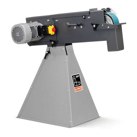
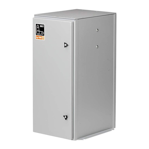
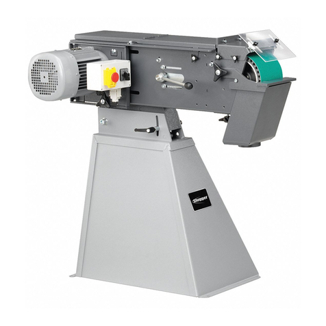
Fein Grit GX75 Series User manual

3 94 10 009 000 • 07.06 • Abbildungen unverbindlich. Technische Änderungen vorbehalten. © C. E.FEIN GmbH • Printed in Germany.
98/37/EU, 89/336/EU, 73/23/EU.
Jørn Toft
Manager
Steen Mølsted
Quality Manager
FEIN Service
Kundendienst
C. E. FEIN GmbH
Feinstraße 3
D-72820 Sonnenbühl
Telefon 0 71 28/3 88 163
Telefax 0 71 28/3 88 169
Firmensitz
C. E. FEIN GmbH
Hans-Fein-Straße 81
D-73529 Schwäbisch Gmünd/Bargau
www.fein.com
Vertrieb
C. E. FEIN GmbH
Leuschnerstraße 43
D-70176 Stuttgart
Telefon 07 11/66 65-0
Telefax 07 11/66 65-249
GRIT GX 75
GX75 - Titel Seite 1 Freitag, 15. Juni 2007 10:01 10

2
Deutsch ____________ Gebrauchsanleitung________________
English _____________ Instruction manual ________________
Français ____________ Notice d'utilisation ________________
Italiano _____________ Libretto delle Istruzioni per l’uso_______
Nederlands __________ Gebruiksaan ijzing ________________
Español_____________ Instrucciones de uso _______________
Português ___________ Instrução de serviço _______________
EÏÏËÓÈο ____________ √‰ËÁ›Â˜ ¯ÂÈÚÈÛÌÔ‡ _________________
Dansk ______________ Brugsanvisning ___________________
Norsk ______________ Bruksanvisning ___________________
Svenska ____________ Bruksanvisning___________________
Suomi ______________ Käyttöohje ______________________
Magyar _____________ Használati útmutató _______________
âesky______________ Návod k pouÏití___________________
Slovensky ___________ Návod na pouÏívanie _______________
Polski______________ Instruk ja obs∏ugi _________________
На русском языке ___ Руководство по эксплуатации __
_____________
____________________
6
12
18
24
30
36
42
48
54
60
66
72
78
84
90
96
102
107
GX75 - Inhalt Seite 2 Freitag, 15. Juni 2007 9:55 09

3
12x
1
24x
1
2
3
12x
GX75.book Seite 3 Freitag, 15. Juni 2007 9:43 09

4
4
6
7
11
14
15
19 20 21
23
10
22
89
3
24
5
12
13
16
17
18
25
3
4
GX 75 2H..
GX 75
1
GX75.book Seite 4 Freitag, 15. Juni 2007 9:43 09

5
max 2 mm
max 2 mm
1012
7
56
78
910
13
1
GX75.book Seite 5 Freitag, 15. Juni 2007 9:43 09

6
GX 75
DE
Ver endete Symbole, Abkürzungen
und Begriffe.
Die in dieser Gebrauchsanleitung und ggf. auf
der Maschine erwendeten Symbole dienen
dazu, Ihre Aufmerksamkeit auf mögliche Gefähr-
dungen bei der Arbeit mit dieser Maschine zu
lenken.
Zu Ihrer Sicherheit.
Verwenden Sie diese Maschine nicht,
be or Sie diese Gebrauchsanleitung gründ-
lich gelesen und ollständig erstanden haben,
einschließlich der Abbildungen, Spezifikationen
und Sicherheitsregeln.
Beachten Sie ebenso die einschlägigen nationa-
len Bestimmungen für elektrische Sicherheit und
Arbeitsschutz (in Deutschland: BGV A2,
BGR 500).
Die Nichtbeachtung der Sicherheitshinweise
kann zum elektrischen Schlag, Brand und/oder
einer ernsten Verletzung führen.
Diese Gebrauchsanleitung zum späteren
Gebrauch aufbewahren und bei einer Weiter-
gabe oder Veräußerung der Maschine überrei-
chen.
Achten Sie auf den sicheren Stand und aage-
rechte Aufstellung des Untergestells. Befestigen
Sie das Untergestell am Boden. Kippt das Unter-
gestell während der Arbeit kann dies schwere
Verletzungen erursachen.
Ver enden Sie zur Montage der Maschine auf dem
Untergestell passendes Befestigungsmaterial.
Eine fehlerhafte Montage kann dazu führen, dass
sich die Maschine während des Arbeits organges
om Untergestell löst und schwere Unfälle er-
ursacht.
Benutzen Sie, Schutzbrille, Schutzhand-
schuhe und einen Gehörschutz. Benutzen Sie,
falls erforderlich Staubmaske und Arbeits-
schürze, die geeignet sind, Sie vor Schleifp-
artikel und Werkstückteilchen zu schützen.
Die Schutzbrille muss sich eignen, die bei
unterschiedlichen Arbeiten weggeschleu-
derten Partikel abzuwehren. Die Staub- oder die
Atemschutzmaske muss fähig sein, die bei der
Arbeit entstehenden Partikel zu filtern. Eine
dauerhaft hohe Lärmbelastung kann zu Gehör-
erlust führen.
Tragen Sie beim Arbeiten keine lose Kleidung,
Schmuck oder offene, lange Haare. Lose Gegen-
stände können trotz Schutz orrichtungen on
sich bewegenden Teilen erfasst werden und zu
Verletzungen führen.
Ver enden Sie keine verschlissenen, eingerisse-
nen oder stark zugesetzten Schleifbänder. Hand-
haben Sie Schleifbänder sorgsam und be ahren
Sie diese nach den An eisungen des Herstellers
auf. Schleifbänder nicht knicken! Beschädigte
Schleifbänder können zerreißen, weggeschleu-
dert werden und jemanden erletzen.
Ver enden Sie keine Schleifbänder oder sonstiges
Zubehör, das nicht speziell vom Hersteller ent i-
ckelt oder freigegeben urde. Sicherer Betrieb ist
nicht alleine dadurch gegeben, dass ein Schleif-
band oder Zubehör auf Ihre Maschine passt.
Symbol Begriff, Bedeutung
➤Aktion
Berühren erboten
Allgemeines Gebotszeichen
Dokumentation lesen
Augenschutz benutzen
Gehörschutz benutzen
Staubschutz benutzen
Handschutz benutzen
Warnung or Gefahr
Europäisches Konformitätszeichen
GX75.book Seite 6 Freitag, 15. Juni 2007 9:43 09

GX 75
7
DE
Ver enden Sie immer die an der Maschine befind-
lichen Schutzvorrichtungen. Die Schutzvorrichtun-
gen müssen sicher an der Maschine montiert sein,
so dass ein Höchstmaß an Sicherheit erreicht
ird. Die Schutz orrichtungen sollen den Bedie-
ner or umherfliegenden Schleifpartikeln und
unbeabsichtigter Berührung mit dem Schleif-
band schützen.
Achtung Brand- und Explosionsgefahr! Beim
Schleifen von Metallen (z. B. Aluminium oder Mag-
nesium) entsteht Staub, der brennbar oder explo-
siv sein kann. Betreiben Sie die Maschine nicht in
der Nähe brennbarer Materialien. Funken können
diese Materialien entzünden.
Achtung Brandgefahr! Beim Schleifen von Metal-
len entstehen glühende Metall- und Schleifbandp-
artikel, die im Spänekasten gesammelt erden.
Der Inhalt des Spänekasten muss or dem Ent-
leeren ausreichend abgekühlt sein und darf nur
über geeignete Behälter entsorgt werden.
Achten Sie darauf, dass keine Personen durch Fun-
kenflug gefährdet erden. Entfernen Sie brenn-
bare Materialien aus der Nähe. Beim Schleifen
on Metallen entsteht Funkenflug.
Das Werkstück muss immer sicher auf der
Schleifauflage und dem Anschlag aufliegen. Zu
kleine oder dünne Werkstücke dürfen nicht bear-
beitet erden. Es besteht Verletzungsgefahr
durch das weggeschleuderte Werkstück.
Berühren Sie niemals das laufende Schleif-
band. Es besteht Verletzungsgefahr.
Drücken Sie in Gefahrensituationen sofort den Not-
Ausschalter. Die Maschine läuft bis zu 50 Sekun-
den nach.
Reinigen Sie regelmäßig die Lüftungsöffnungen
der Maschine. Das Motorgebläse zieht Staub in
das Gehäuse. Dies kann bei übermäßiger
Ansammlung on Metallstaub elektrische
Gefährdungen erursachen.
Der Stecker der Maschine darf nur von einem Elek-
trofachmann montiert erden. Der Schutzleiter
in der Netzsteckdose muss mit der Schutzer-
dung des Stromnetzes erbunden sein.
Bei Wartung und Instandsetzung den Netzstecker
ziehen! Wird die Maschine unbeabsichtigt einge-
schaltet, kann dies zu schweren Verletzungen
führen.
Lassen Sie die elektrische Sicherheit der Maschine
den gesetzlichen Bestimmungen entsprechend
regelmäßig überprüfen. Bei nicht geprüften
Maschinen besteht die Gefahr eines elektrischen
Schlags!
Prüfen Sie vor der ersten Inbetriebnahme die
Drehrichtung des Motors. Bei falscher Drehrich-
tung kann das Werkstück weggeschleudert wer-
den und Unfälle erursachen. Die Drehrichtung
darf nur on einem Elektrofachmann umgestellt
werden.
Stehen Sie oder andere Personen beim Einschalten
der Maschine niemals direkt neben dem Schleif-
band. Das Schleifband kann reißen und schwere
Verletzungen erursachen.
Auf einen Blick.
1 Spannhebel, Untergestell
2 Schraube
3 Untergestell
4 Schutzabdeckung, oben
5 Spannhebel, Bandspannung
6 Sterndrehschraube, Schutzabdeckung
7 Anschlag
8 Flügelschrauben, Funkenschutz
9 Funkenschutz
10 Schleifauflage
11 Spänekasten
12 Sterndrehschraube für Schleifauflage
13 Einstellschraube, Planschleifauflage
14 Sterndrehschraube, Bandlaufjustierung
15 NOT-Aus-Taste
16 Lüftungsschlitze
17 Ein-/Ausschalter
18 Drehzahlumschaltung (nur 2H-Modelle)
19 Kontaktscheibe
20 Planschleifauflage
21 Antriebsscheibe
22 Schraube für Seitendeckel
23 Seitendeckel
24 Stutzen für Staubabsaugung
25 Hin eisschild
GX75.book Seite 7 Freitag, 15. Juni 2007 9:43 09
8
GX 75
DE
Bestimmung der Maschine.
Die Maschine ist bestimmt für das stationäre
Schleifen on Metallwerkstoffen und zum
Schleifen mit dem Radienschleifmodul GRIT
GXR oder der Rundschleif orrichtung GRIT
GXC unter Verwendung om Hersteller zuge-
lassener Schleifbänder.
Montagean eisungen.
Montieren Sie das Untergestell wie darge-
stellt.
Legen Sie die Maschine mit der Oberseite
nach unten auf den Boden und montieren
Sie das Untergestell gemäß Abbildung und
DVD.
Befestigen Sie das Untergestell mit geeig-
neten Dübel-/Schraub erbindungen am
Boden. Die Befestigung muss den bei der Arbeit
auftretenden Kräften genügen.
Wegen der Unfallgefahr muss diese Arbeit
on Personen ausgeführt werden, die kör-
perlich in der Lage sind, das hohe Maschinenge-
wicht zu heben.
Elektroanschluss.
Der bauseitige Elektroanschluss muss on
einem Elektrofachmann orgenommen
werden.
Netzspannung beachten: Die Netzspannung und
Frequenz der Spannungsquelle muss mit den
Angaben auf dem Typenschild der Maschine
übereinstimmen.
Überprüfen Sie or der ersten Inbetriebnahme
die Drehrichtung des Motors. Die Drehrichtung
darf nur on einem Elektrofachmann umgestellt
werden.
Einstellungen.
Ziehen Sie vor allen Arbeiten an der
Maschine den Stecker aus der Steckdose.
Neigung einstellen (Bild 10)
➤Lösen Sie die beiden Spannhebel (1). Stellen
Sie die Maschine auf die erforderliche
Arbeitshöhe ein.
➤Ziehen Sie die beiden Spannhebel (5) wie-
der fest.
Schleifauflage (10) einstellen (Bild 5).
➤Lösen Sie die Sterndrehschraube (12) und
stellen Sie das Spaltmaß on max. 2 mm ein.
➤Ziehen Sie die Sterndrehschraube wieder
fest.
Planschleifauflage (20) einstellen.
Beim Planschleifen muss die Planschleifauf-
lage (20) parallel zum Schleifband ausgerichtet
sein und es auf der ganzen Fläche berühren.
➤Lösen Sie die Schraube (22) und klappen Sie
den Seitendeckel (23) herunter.
➤Lösen Sie die Schrauben (13) und richten
Sie die Planschleifauflage (20) aus. Ziehen
Sie die Schrauben (13) wieder fest.
➤Schließen Sie den Seitendeckel (23) und zie-
hen Sie die Schraube (22) wieder fest.
Überprüfen Sie das Spaltmaß am
Anschlag (7). (Bild 6)
Bandlauf justieren.
Schalten Sie die Maschine nur
kurz ein und überprüfen Sie
den Bandlauf.
Justieren Sie den Bandlauf mit
der Sterndrehschraube (14)
mittig, wenn sich das Schleifband nach rechts
oder links bewegt.
Falls sich der Bandlauf nicht mittig einstellen
lässt:
➤Reinigen Sie das Antriebsscheibe (21) und
das Kontaktscheibe (19) mit Druckluft.
➤Überprüfen Sie das Antriebsscheibe und das
Kontaktscheibe auf Verschleiß, Verformung
und Abnutzung. Lassen Sie beschädigte Teile
sofort ersetzen!
Schleifband echseln.
Ziehen Sie vor allen Arbeiten an der
Maschine den Stecker aus der Steckdose.
➤Lösen Sie die Schraube (22) und klappen Sie
den Seitendeckel (23) herunter. (Bild 4)
➤Lösen Sie die Sterndrehschraube (12) und
entfernen Sie den Spänekasten (11).
GX75.book Seite 8 Freitag, 15. Juni 2007 9:43 09

GX 75
9
DE
Schwenken Sie den Hebel (5)
nach unten um die Spann or-
richtung zu entlasten.
➤Entfernen Sie das alte Schleif-
band.
Beachten Sie or dem Auflegen des neuen
Schleifbandes die Laufrichtungsangabe auf der
Schleifbandrückseite! Sie muss mit der Dreh-
richtung des Antriebsrades übereinstimmen.
➤Legen Sie das Schleifband gleichzeitig auf das
Antriebsscheibe (21) und das Kontakt-
scheibe (19).
Schwenken Sie den Hebel (5)
nach oben um das Schleifband
zu spannen.
➤Schließen Sie den Seitende-
ckel (23) und ziehen Sie die
Schraube (22) wieder fest.
➤Montieren Sie den Spänekasten (11) und
prüfen Sie das Spaltmaß der Schleifauflage.
➤Schalten Sie die Maschine ein und justieren
Sie den Bandlauf.
Betriebsan eisungen
Einschalten:
➤NOT-Aus-Taste (15) entriegeln und auf-
klappen. Taste „I“ (17) drücken.
Ausschalten:
➤NOT-Aus-Taste (15) aufklappen. Taste
„0“ (17) drücken.
Die Maschine läuft nach dem Ausschalten
ca. 50 sek. nach.
NOT-Aus-Taste:
➤Drücken Sie in Gefahrensituationen die rote
NOT-Aus-Taste um die Maschine auszu-
schalten.
Drehzahl umschalten (Modelle 2H).
➤Schalterposition 1: Niedrige Drehzahl
➤Schalterposition 2: Hohe Drehzahl
Die Drehzahl darf nur bei stillstehender
Maschine mit dem Schalter (18) umge-
schaltet werden.
Überlastsicherung.
Bei einer anhaltend hohen Belastung über einen
längeren Zeitraum wird die Maschine abgeschal-
tet. Nach einer Abkühlzeit on ca. 15 Minuten ist
die Maschine wieder einsatzbereit.
Kontaktschleifen (Bilder 7+8).
➤Vergewissern Sie sich, dass die Sterndreh-
schraube (12) festgezogen ist.
➤Stellen Sie sicher, dass die obere Schutzab-
deckung (4) mit der Sterndrehschraube (6)
gesichert und der Seitendeckel (23)
geschlossen ist.
➤Prüfen Sie das Spaltmaß der Schleifauflage.
➤Prüfen Sie die Position der Planschleifauf-
lage (20). Die Schrauben (13) müssen sich in
der unteren Position befinden.
Prüfen Sie ob die Flügelschrauben (8) des
Augenschutzes (9) richtig festgezogen sind.
➤Schalten Sie die Maschine ein und prüfen Sie
den Bandlauf.
➤Legen Sie das Werkstück fest auf die
Schleifauflage auf.
➤Das Werkstück mit beiden Händen führen
oder in einer Vorrichtung fixieren.
Planschleifen (Bild 9).
➤Lösen Sie die Sterndrehschrauben (6) und
entfernen Sie die obere Schutzabde-
ckung (4).
➤Stellen Sie sicher, dass das Spaltmaß richtig
eingestellt ist. (Bild 6)
➤Schalten Sie die Maschine ein und prüfen Sie
den Bandlauf.
➤Das Werkstück mit beiden Händen führen
und nach dem Arbeits organg nach oben
wegnehmen.
Absaugvorichtung
➤Die Maschine kann über den Stutzen (24) an
eine Absaug orrichtung angeschlossen wer-
den.
GX75.book Seite 9 Freitag, 15. Juni 2007 9:43 09

10
GX 75
DE
Instandhaltung und Kundendienst.
Eine Instandsetzung darf nur durch eine
Fachkraft nach den gültigen Vorschriften
durchgeführt werden.
Zur Instandsetzung empfehlen wir den FEIN-
Kundendienst, die FEIN-Vertragswerkstätte und
die FEIN-Vertretungen.
Führen Sie die folgenden Wartungsarbeiten
regelmäßig durch:
Blasen Sie die Kühlluftöffnungen (16) am
Motorgehäuse und die gekennzeichneten
Stellen mit Druckluft aus (siehe Hinweis-
schild (25)).
Ölen Sie die Maschine täglich an den
gekennzeichneten Stellen mit Maschinenöl
(siehe Hinweisschild (25)).
➤Überprüfen Sie das Antriebsscheibe und das
Kontaktscheibe beim jedem Schleifband-
wechsel auf Verschleiß und Beschädigungen.
Lassen Sie beschädigte Teile ersetzen.
Ge ährleistung und Garantie.
Die Gewährleistung auf das Erzeugnis gilt gemäß
den gesetzlichen Regelungen im Lande des
In erkehrbringens.
Darüber hinaus leistet FEIN Garantie entspre-
chend der FEIN-Hersteller-Garantieerklärung.
Details diesbezüglich erfahren Sie bei Ihrem
Fachhändler, der FEIN-Vertretung in Ihrem Land
oder beim FEIN-Kundendienst.
Konformitätserklärung.
Die Firma GRIT erklärt in alleiniger Verantwor-
tung, dass dieses Produkt den auf der letzten
Seite dieser Gebrauchsanleitung angegebenen
einschlägigen Bestimmungen entspricht.
Um eltschutz, Entsorgung.
Stationärmaschinen sollen gemäß nationalem
Recht einer umweltgerechten Wieder erwer-
tung zugeführt werden.
Technische Daten.
Typ GX 75 GX 75 GX 75 AUS GX 75 AUS GX 75 2V GX 75 2V
Bestellnummer 7 902 01 00 40 3 7 902 01 00 40 3 7 901 01 06 44 3 7 901 01 06 44 3 7 902 01 00 23 3 7 902 01 00 23 3
Leerlaufdreh-
zahl [min]2 880 3 450 2 880 3 450 2 880 3 450
Leistungsauf-
nahme [W]3 000 3 000 3 000 3 000 3 000 3 000
Spannung [V]3x400 3x440 3x400 3x440 3x230 3x220
Frequenz [Hz]50 60 50 60 50 60
Schleifbandge-
schwindigkeit
[m/s]30 36 30 36 30 36
Gewicht ent-
sprechend
EPTA-
Procedure
01/2003 [kg]65 65 65 65 65 65
Schutzklasse I/ I/ I/ I/ I/ I/
Schleifband-
länge [mm]2 000 2 000 2 000 2 000 2 000 2 000
Schleifband-
breite [mm]75 75 75 75 75 75
GX75.book Seite 10 Freitag, 15. Juni 2007 9:43 09

GX 75
11
DE
Anschlussschaltbilder.
Typ GX 75, Anlage 111
Typ GX 75 2V, Anlage 112
Typ GX 75 2H, Anlage 113
Typ GX 75 2H2V, Anlage 114
Geräusch-Emissions erte.
Typ GX 75 2H GX 75 2H GX 75 2HAUS GX 75 2HAUS GX 75 2H2V GX 75 2H2V
Bestellnummer 7 902 02 00 40 3 7 902 02 00 40 3 7 901 02 06 44 3 7 901 02 06 44 3 7 902 02 00 23 3 7 902 02 00 23 3
Leerlaufdreh-
zahl [min]1 440/2 880 1 725/3 450 1 440/2 880 1 725/3 450 1 440/2 880 1 725/3 450
Leistungsauf-
nahme [W]1 500/2 000 1 500/2 000 1 500/2 000 1 500/2 000 1 500/2 000 1 500/2 000
Spannung [V]3x400 3x440 3x230 3x440 3x230 3x220
Frequenz [Hz]50 60 50 60 50 60
Schleifbandge-
schwindigkeit
[m/s]15/30 18/34 15/30 18/34 15/30 18/34
Gewicht ent-
sprechend
EPTA-
Procedure
01/2003 [kg]67 67 67 67 67 67
Schutzklasse I/ I/ I/ I/ I/ I/
Schleifband-
länge [mm]2 000 2 000 2 000 2 000 2 000 2 000
Schleifband-
breite [mm]75 75 75 75 75 75
Gemessener A-bewerteter Schallleistungspegel
LwA (re 1 pW), in Dezibel: 86
Unsicherheit KwA, in Dezibel: 3
Gemessener A-bewerteter Emissions-Schall-
druckpegel am Arbeitsplatz LpA (re 20 µPa),
in Dezibel: 78
Unsicherheit KpA, in Dezibel: 3
ANMERKUNG: Die Summe aus gemessenem
Emissionswert und zugehöriger Unsicherheit
stellt die obere Grenze der Werte dar, die bei
Messungen auftreten können.
Gehörschutz benutzen!
Messwerte ermittelt nach zutreffender Produkt-
norm (siehe die letzte Seite dieser Gebrauchsan-
leitung).
GX75.book Seite 11 Freitag, 15. Juni 2007 9:43 09

12
GX 75
EN
Symbols, abbreviations and terms
used.
The symbols used in this Instruction Manual and
where necessary on the machine, ser e to draw
your attention to possible hazards when work-
ing with this machine.
For your safety.
Do not use this machine before you ha e
thoroughly read and completely under-
stood this Instruction Manual, including the fig-
ures, specifications and safety regulations.
Please also obser e the rele ant national indus-
trial safety regulations (e. g. in Germany:
BGV A2, BGR 500).
Non-obser ance of the safety instructions can
lead to an electric shock, fire and/or se ere inju-
ries.
This Instruction Manual should be kept for later
use and enclosed with the machine, should it be
passed on or sold.
Make sure that the undercarriage stands securely
and has a level setup position. Fasten the under-
carriage to the ground. If the undercarriage tips
o er during operation, serious injuries can
result.
Use appropriate fastening material hen mount-
ing the machine to the undercarriage. When
mounted incorrectly, the machine can come
loose from the undercarriage and cause serious
accidents.
Use safety glasses, protective gloves and
hearing protection. As appropriate, ear a
dust mask and shop apron capable of pro-
tecting you against grinding and ork piece
particles. The safety glasses must be capa-
ble of protecting against flying particles
generated by the arious different opera-
tions. The dust mask or respirator must be capa-
ble of filtering particles generated by your
operation. Prolonged exposure to high intensity
noise may cause loss of hearing.
While orking, do not ear loose clothing, je el-
lery, open or long hair. Loose objects can be
caught in mo ing parts despite protecti e
de ices, and lead to injuries.
Do not use orn, torn or heavily clogged grinding
belts. Handle grinding belts ith care and store
them in accordance ith the instructions of the
manufacturer. Do not bend or crease grinding
belts! Damaged grinding belts can tear apart and
be thrown from the machine resulting in possi-
ble personal injury.
Do not use grinding belts or other accessories
hich are not specifically designed and recom-
mended by the po er tool manufacturer. Safe
operation is not ensured merely because a
grinding belt or accessory fits your machine.
Al ays use the protective devices of the machine.
The protective devices must be securely mounted
to the machine and positioned for maximum
safety. The protecti e de ices help to protect
the operator from flying grinding particles and
unintentional contact with the grinding belt.
Caution! Danger of fire and explosion! When grind-
ing metals (e. g. aluminium or magnesium), dust
develops that can be combustible or explosive. Do
not operate the machine in the vicinity of combus-
tible materials. Sparks can ignite such materials.
Symbol Term, meaning
➤Action
Touching prohibited
General mandatory sign
Read documentation
Use eye-protection
Wear ear protection
Use dust mask
Use protecti e glo es
Danger warning
European conformity symbol
GX75.book Seite 12 Freitag, 15. Juni 2007 9:43 09

GX 75
13
EN
Caution! Danger of fire! When grinding metals, red
hot metal and grinding belt particles develop and
are collected in the dust collector. Before empty-
ing, the contents of the dust collector must ha e
cooled sufficiently and may be disposed only in
suitable containers.
Pay attention that persons are not harmed by
sparking. Remo e combustible materials in the
direct area. Sparks de elop when grinding met-
als.
The orkpiece must al ays lie securely on the
grinding rest and the stop. Workpieces that are
too small or too thin may not be orked. Danger
of injury from workpieces being thrown from
the machine.
Never touch the running grinding belt. Dan-
ger of injury.
Press the emergency-off s itch immediately in
danger situations. The machine runs on for up to
50 seconds.
Clean the ventilation slots of the machine regu-
larly. The motor fan dra s dust into the housing.
Excessi e accumulation of metal dust can cause
electrical dangers.
The mains plug of the machine may be mounted
only by a qualified electrician. The protecti e
conductor in the mains socket outlet must be
connected with the protecti e earthing of the
mains supply.
Pull out the mains plug for maintenance and
repair! Switching the machine on unintentionally
can lead to serious injuries.
Have the electrical safety of the machine checked
regularly in accordance ith statutory regula-
tions. For machines that ha e not been checked,
there may be danger of electrical shock!
Check the rotation direction of the motor before
starting the operation of the machine for the first
time. If the rotation direction of the motor is
incorrect, the workpiece can be thrown from
the machine and cause an accident. The rotation
direction may be changed only by a qualified
electrician.
Make sure that you or other persons are not
standing directly next to the grinding belt hen
s itching the machine on. The grinding belt can
tear apart and cause serious injuries.
At a glance.
1 Tension lever, undercarriage
2 Bolt
3 Undercarriage
4 Protective cover, top
5 Belt tension lever
6 Star-knob bolt for protective cover
7 Stop
8 Spark guard ing bolts
9 Spark guard
10 Grinding rest
11 Dust collector
12 Star-knob bolt for grinding rest
13 Adjustment scre for face- grinding rest
14 Star-knob bolt for adjusting the tracking of the
grinding belt
15 Emergency OFF pushbutton
16 Ventilation slots
17 On/Off s itch
18 Speed s itch (only for 2H models)
19 Contact heel
20 Face- grinding rest
21 Drive heel
22 Scre for side cover
23 Side cover
24 Connection sleeve for dust extraction
25 Instruction label
Intended use of the machine.
The machine is intended for stationary sanding/
grinding of metal materials and for use with
radius grinding module GXR or centerless
unit GXC using manufacturer appro ed grinding
belts.
Mounting instructions.
Assemble the undercarriage as shown.
Place the machine on the floor with the top
side facing down and mount the undercar-
riage according to the figure and instructions on
the DVD.
GX75.book Seite 13 Freitag, 15. Juni 2007 9:43 09

14
GX 75
EN
Fasten the undercarriage to the ground
with suitable anchor/screw connections.
The fastening must be suitable to withstand the
forces occurring during working.
Due to the danger of accidents, this work
must be carried out by persons that are
physically capable of lifting the high weight of the
machine.
Electrical connection.
The electrical connection, which is to be
pro ided by customer, must be carried out
by a qualified electrician.
Observe mains voltage: The mains oltage and
the frequency of the power source must agree
with the data on the type plate of the machine.
Before starting operation for the first time,
check the rotation direction of the motor. The
rotation direction may be changed only by a
qualified electrician.
Adjustments.
Before any ork on the machine itself, pull
the po er plug from the socket outlet.
Adjusting the incline (Figure 10)
➤Loosen both clamping le ers (1). Adjust the
machine to the required working height.
➤Tighten both clamping le ers (1) again.
Adjusting the grinding rest (10) (Figure 5).
➤Loosen star-knob bolt (12) and adjust the
gap size to 2 mm (max.).
➤Tighten the star-knob bolt again.
Adjusting the face- grinding rest (20).
For face grinding applications, the face- grinding
rest (20) must be aligned parallel to the grinding
belt and must touch it o er the complete sur-
face.
➤Loosen screw (22) and fold the side
co er (23) down.
➤Loosen screws (13) and align the face-grind-
ing rest (20). Tighten the screw (13) again.
➤Shut the side co er (23) and tighten
screw (22) again.
Check the gap size at the stop (7).
(Figure 6)
Adjusting the belt tracking.
Switch the machine on only
briefly and check the belt track-
ing.
If the grinding belt mo es left or
right, adjust the belt tracking
with the star-knob bolt (14) until centred.
If the belt tracking cannot be adjusted centred:
➤Clean the dri e wheel (21) and the contact
wheel (19) with compressed air.
➤Check the dri e wheel and the contact
wheel for wear, deformation and damage.
Ha e damaged components replaced with-
out delay!
Changing the grinding belt.
Before any ork on the machine itself, pull
the po er plug from the socket outlet.
➤Loosen screw (22) and fold the side
co er (23) down. (Figure 4)
➤Loosen star-knob bolt (12) and remo e the
dust collector (11).
Push belt tension le er (5)
down to release the clamping
de ice.
➤Remo e the old grinding belt.
Before attaching the new grinding belt, obser e
the information concerning the running direc-
tion on the inner side of the grinding belt! It
must correspond with the running direction of
the dri e wheel.
➤Place the grinding belt both around the dri e
wheel (21) and around the contact
wheel (19).
Push the belt tension le er (5)
up again to tension the grinding
belt.
➤Shut the side co er (23) and
tighten screw (22) again.
➤Remount the dust collector (11) and check
the gap size at the grinding rest.
➤Switch the machine on and adjust the belt
run.
GX75.book Seite 14 Freitag, 15. Juni 2007 9:43 09

GX 75
15
EN
Operating instructions
S itching ON:
➤Release the emergency OFF pushbut-
ton (15) and lift it up. Press the “I” but-
ton (17).
S itching OFF:
➤Lift up the emergency OFF pushbutton (15).
Press the “0” (17) button.
After switching off, the machine runs on
for approx. 50 seconds.
Emergency OFF pushbutton:
➤In emergency situations, press the red emer-
gency OFF pushbutton to switch the
machine off.
Changing the speed (models 2H).
➤Switch position 1: Low speed
➤Switch position 2: High speed
Change the speed of the machine only
when the machine is at a complete stop
with the speed switch (18).
Overload protection.
In case of continuous high load o er a longer
period of time, the machine is switched off. After
a cooling-down period of approx. 15 minutes,
the machine is ready for operation again.
Contact grinding (Figures 7+8).
➤Check if the star-knob bolt (12) is firmly
tightened.
➤Ensure that the top protecti e co er (4) is
secured with star-knob bolt (6) and that the
side co er (23) is shut.
➤Check the gap size of the grinding rest.
➤Check the position of the face-grinding
rest (20). The adjustment screws (13) must
be in the bottom position.
Check if the screws (8) of spark guard (9) are
properly tightened.
➤Switch the machine on and check the belt
run.
➤Place the workpiece firmly onto the grinding
rest.
➤Guide the workpiece with both hands or
fasten it in a fixture.
Face grinding (Figure 9).
➤Loosen the star-knob bolts (6) and remo e
the top protecti e co er (4).
➤Make sure that the gap size is correctly
adjusted. (Figure 6)
➤Switch the machine on and check the belt
run.
➤Guide the workpiece with both hands and
remo e it to upward after the working pro-
cedure.
Extraction device
➤The machine can be connected ia the
slee e (24) to a dust extraction system.
Repair and customer service.
Repairs may be carried out only by quali-
fied persons in conformity with the alid
regulations.
For repairs, we recommend our FEIN customer
ser ice centre, the FEIN authorised ser ice cen-
tres and FEIN agencies.
Carry out the following maintenance regularly:
Blow out the entilation slots (16) at the
motor housing and the marked locations
with compressed air (see Instruction
label (25)).
Lubricate the machine daily (when in use)
with machine oil at the locations marked
(see Instruction label (25)).
➤Check the dri e wheel and the contact
wheel for wear and damage each time when
changing the grinding belt. Ha e damaged
parts replaced.
Warranty and liability.
The warranty for the product is alid in accord-
ance with the legal regulations in the country
where it is marketed.
In addition, FEIN also pro ides a guarantee in
accordance with the FEIN manufacturer’s guar-
antee. For further details on this, please contact
your specialist dealer, your national FEIN repre-
sentati e, or the FEIN customer ser ice centre.
GX75.book Seite 15 Freitag, 15. Juni 2007 9:43 09

16
GX 75
EN
Declaration of conformity.
The GRIT Corp. declares itself solely responsible
for this product conforming to the documents
and standards gi en on the last page of this
Instruction Manual.
Environmental protection, disposal.
Stationary machines should be sorted for en i-
ronment-friendly recycling in accordance with
national laws.
Specifications.
Type GX 75 GX 75 GX 75 AUS GX 75 AUS GX 75 2V GX 75 2V
Reference
number 7 902 01 00 40 3 7 902 01 00 40 3 7 901 01 06 44 3 7 901 01 06 44 3 7 902 01 00 23 3 7 902 01 00 23 3
No-load speed
[min]2 880 3 450 2 880 3 450 2 880 3 450
Power input
[W]3 000 3 000 3 000 3 000 3 000 3 000
Voltage [V]3x400 3x440 3x400 3x440 3x230 3x220
Frequency [Hz]50 60 50 60 50 60
Grinding-belt
speed [m/s]30 36 30 36 30 36
Weight accord-
ing to EPTA-
Procedure
01/2003 [kg]65 65 65 65 65 65
Class of protec-
tion I/ I/ I/ I/ I/ I/
Grinding-belt
length [mm]2 000 2 000 2 000 2 000 2 000 2 000
Grinding-belt
width [mm]75 75 75 75 75 75
Type GX 75 2H GX 75 2H GX 75 2HAUS GX 75 2HAUS GX 75 2H2V GX 75 2H2V
Reference
number 7 902 02 00 40 3 7 902 02 00 40 3 7 901 02 06 44 3 7 901 02 06 44 3 7 902 02 00 23 3 7 902 02 00 23 3
No-load speed
[min]1 440/2 880 1 725/3 450 1 440/2 880 1 725/3 450 1 440/2 880 1 725/3 450
Power input
[W]1 500/2 000 1 500/2 000 1 500/2 000 1 500/2 000 1 500/2 000 1 500/2 000
Voltage [V]3x400 3x440 3x230 3x440 3x230 3x220
Frequency [Hz]50 60 50 60 50 60
Grinding-belt
speed [m/s]15/30 18/34 15/30 18/34 15/30 18/34
Weight accord-
ing to EPTA-
Procedure
01/2003 [kg]67 67 67 67 67 67
Class of protec-
tion I/ I/ I/ I/ I/ I/
Grinding-belt
length [mm]2 000 2 000 2 000 2 000 2 000 2 000
Grinding-belt
width [mm]75 75 75 75 75 75
GX75.book Seite 16 Freitag, 15. Juni 2007 9:43 09

GX 75
17
EN
Connection diagrams.
Type GX 75, Appendix 111
Type GX 75 2V, Appendix 112
Type GX 75 2H, Appendix 113
Type GX 75 2H2V, Appendix 114
Noise emission values.
Measured A-weighted sound power le el LwA
(re 1 pW), in decibels: 86
Measuring uncertainty KwA, in decibels: 3
A-weighted emission pressure power le el
measured at the workplace LpA (re 20 µPa),
in decibels: 78
Measuring uncertainty KpA, in decibels: 3
REMARK: The sum of the measured emission
alue and respecti e measuring inaccuracy rep-
resents the upper limit of the alues that can
occur during measuring.
Wear ear protection!
For measurement alues obtained according to
the respecti e product standard, see the last
page of this Instruction Manual.
GX75.book Seite 17 Freitag, 15. Juni 2007 9:43 09
18
GX 75
FR
Symboles, abréviations et termes
utilisés.
Les symboles utilisés dans cette notice d’utilisa-
tion et, le cas échéant, sur l’appareil, ser ent à
attirer otre attention sur les dangers é entuels
que comporte le tra ail a ec cet appareil.
Pour votre sécurité.
Ne pas utiliser cet appareil a ant d’a oir
soigneusement lu et complètement com-
pris cette notice d’utilisation, y compris les figu-
res, les spécifications et les règles de sécurité.
Tenir également compte des règlementations
nationales de sécurité électrique et protection
du tra ail en igueur (en Allemagne : BGV A2,
BGR 500).
Le non-respect des instructions de sécurité peut
entraîner un choc électrique, un incendie et / ou
de gra es blessures.
Bien garder cette notice d’utilisation en ue
d’une utilisation ultérieure ; elle doit être jointe
à l’appareil en cas de cession ou de ente à une
tierce personne.
Veiller à placer le socle dans une position stable
et à l’horizontale. Fixer le socle sur le sol. Au cas
où le socle se ren erserait pendant le tra ail, ceci
pourrait entraîner de gra es blessures.
Utiliser des dispositifs de fixation appropriés pour
monter l’appareil sur le socle. Un montage incor-
rect peut pro oquer de gra es accidents causés
par un appareil qui s’est détaché du socle pen-
dant l’opération de tra ail.
Utiliser des lunettes de protection, des gants
de protection et une protection acoustique.
Le cas échéant, porter un masque anti-pous-
sière et un tablier de travail appropriés pour
vous protéger contre les particules venant
de la meule et de la pièce à travailler. Porter
des lunettes de protection adaptées contre
les particules projetées lors des tra aux. Le mas-
que anti-poussière ou le masque de protection
doit filtrer les particules générées lors du tra ail.
Une exposition permanente au bruit intense
peut pro oquer une perte d’audition.
Ne pas porter des vêtements amples, des bijoux ou
des cheveux longs ouverts lors du travail. Malgré
les dispositifs de protection, des objets non fixés
peu ent être happés par des pièces en mou e-
ment et entraîner des blessures.
Ne pas utiliser de bandes abrasives usées, fen-
dues sur les bords ou fortement encrassées.
Manier avec précaution les bandes abrasives et
les ranger conformément aux instructions du
fabricant. Ne pas plier les bandes abrasives ! Les
bandes abrasi es endommagées peu ent se
déchirer ou être projetées par l’appareil et bles-
ser des personnes.
Ne pas utiliser de bandes abrasives ou d’autres
accessoires qui n’ont pas été spécialement conçus
ou acceptés par le fabricant. Le seul fait qu’une
bande abrasi e ou un accessoire aille sur otre
appareil ne garantit pas une utilisation dépour-
ue de risque.
Toujours utiliser les dispositifs de protection se
trouvant sur l’appareil. Les dispositifs de protec-
tion doivent être bien montés sur l’appareil de
façon à obtenir une sécurité maximale. Les dispo-
sitifs de protection doi ent protéger l’utilisateur
contre les particules qui se détachent et contre
un contact accidentel a ec la bande abrasi e.
Symbole Terme, signification
➤Action
Interdit de toucher
Signal d’obligation général
Lire la documentation
Porter une protection oculaire
Porter une protection acoustique
Porter une protection anti-pous-
sière
Utiliser un protège-main
Mise en garde d’un danger
Signe de conformité européenne
GX75.book Seite 18 Freitag, 15. Juni 2007 9:43 09
GX 75
19
FR
Attention risque d’incendie et d’explosion ! Lors du
ponçage de métaux (par ex. aluminium ou magné-
sium), de la poussière est générée qui peut être
inflammable ou explosive. Ne pas utiliser l’appa-
reil lorsqu’il y a des matériaux inflammables à
proximité. Les étincelles risquent d’enflammer
ces matériaux.
Attention ! Risque d’incendie ! Lors du ponçage de
métaux, des particules incandescentes de métal
et de la feuille abrasive sont générées qui sont
récupérées dans la boîte à copeaux. A ant de
ider la boîte à copeaux, attendre que son con-
tenu soit suffisamment refroidi, n’éliminer le
contenu que dans des conteneurs appropriés.
Veiller à ce que personne ne soit exposé à un dan-
ger en raison des projections d’étincelles. Enle er
les matériaux inflammables se trou ant à proxi-
mité. L’usinage des métaux génère des étincel-
les.
L’outil de travail doit toujours être bien posé sur le
support de ponçage et la butée. Ne pas travailler
des pièces trop petites ou trop fines. Il y a risque
de blessure dû à la pièce de tra ail projetée.
Ne jamais toucher la bande abrasive en rota-
tion. Il y a un risque de blessures.
En cas de danger, toujours appuyer immédiate-
ment sur l’arrêt d’urgence. L’appareil continue à
tourner pendant 50 secondes en iron.
Nettoyer régulièrement les ouïes de ventilation de
appareil. La ventilation du moteur aspire de la
poussière dans le carter. Une trop grande quan-
tité de poussière de métal accumulée peut cons-
tituer des dangers électriques.
Seul un électricien professionnel a le droit de
monter la fiche de l’appareil. Le conducteur de
protection dans la prise du secteur doit être con-
necté à la mise à la terre du réseau électrique.
Pour les travaux d’entretien et de réparation, reti-
rer la fiche de la prise de courant ! Le fait de met-
tre en marche l’appareil par mégarde peut
entraîner de gra es blessures.
Faire régulièrement contrôler la sécurité électri-
que de l’appareil conformément à la législation en
vigueur. Pour les appareils non contrôlés, il y a
risque de choc électrique !
Avant la première mise en service, contrôler le
sens de rotation du moteur. Si c’est le mau ais
sens de rotation, la pièce à tra ailler peut être
projetée et causer des accidents. Seul un électri-
cien professionnel a le droit d’in erser le sens de
rotation.
Lors de la mise en marche de l’appareil, veiller à
ce que l’utilisateur ou d’autres personnes ne se
tiennent pas directement à côté de la bande abra-
sive. La bande abrasi e peut se déchirer et
entraîner de gra es blessures.
Vue générale.
1 Levier de serrage, socle
2 Vis
3 Socle
4 Capot de protection supérieur
5 Levier de serrage, tension de la bande
6 Vis étoile, capot de protection
7 Butée
8 Vis papillon, protection contre les étincelles
9 Protection contre les étincelles
10 Support de ponçage
11 Boîte à copeaux
12 Vis étoile pour support de ponçage
13 Vis de réglage, support de ponçage pour sur-
faces planes
14 Vis étoile, ajustage de la bande
15 Touche Arrêt d’urgence
16 Fentes d’aération
17 Interrupteur Marche/Arrêt
18 Modification de la vitesse de rotation (seule-
ment pour les modèles 2H)
19 Roue de contact
20 Support de ponçage pour surfaces planes
21 Roue d’entraînement
22 Vis pour capot latéral
23 Capot latéral
24 Tubulure pour aspiration des poussières
25 Plaque d’avertissement
GX75.book Seite 19 Freitag, 15. Juni 2007 9:43 09
20
GX 75
FR
Utilisation de l’appareil.
L’appareil est conçu pour le ponçage station-
naire de matériaux métalliques et pour le gru-
geage a ec le module GRIT GXR ou polissage de
tubes cylindriques a ec le module GRIT GXC
sous réser e de l’utilisation de bandes abrasi es
agrées par le fabricant.
Indications de montage.
Monter le socle conformément à la figure.
Déposer l’appareil sur le sol, la face supé-
rieure orientée ers le bas, et monter le
socle conformément à la figure et aux instruc-
tions se trou ant sur le DVD.
A l’aide de is/che illes appropriées, fixer
le socle sur le sol. La fixation doit satisfaire
aux forces générées pendant le tra ail.
En raison du risque d’accident, ce tra ail
doit être effectué par des personnes physi-
quement capables de soule er le poids impor-
tant de l’appareil.
Branchement électrique.
Le branchement électrique sur les lieux
d’installation doit être effectué par un élec-
tricien professionnel.
Respecter la tension du réseau : La tension et la
fréquence de la source de tension doi ent cor-
respondre aux indications rele ées sur la plaque
signalétique de l’appareil.
A ant la première mise en ser ice, contrôler le
sens de rotation du moteur. Seul un électricien
professionnel a le droit d’in erser le sens de
rotation.
Réglages.
Avant d’effectuer des travaux sur l’appareil,
retirer la fiche de la prise du courant.
Régler l’inclinaison (Figure 10)
➤Desserrer les deux le iers de serrage (1).
Régler l’appareil à la hauteur de tra ail néces-
saire.
➤Resserrer les deux le iers de serrage (1).
Ajuster le support de ponçage (10)
(Figure 5).
➤Desserrer la is étoile (12) et régler la cote
de la fente sur 2 mm max.
➤Resserrer la is étoile.
Ajuster le supporte de ponçage pour surfaces
planes (20).
Lors du ponçage de surfaces planes, le sup-
port (20) doit être ajusté en parallèle à la bande
abrasi e et la toucher sur toute sa surface.
➤Desserrer la is (22) et abaisser le capot laté-
ral (23).
➤Desserrer les is (13) et ajuster le support
de ponçage pour surfaces planes(20). Res-
serrer les is (13).
➤Fermer le capot latéral (23) et resserrer la
is (22).
Contrôler la cote de la fente sur la
butée (7). (Figure 6)
Centrage de la bande.
Mettre brièvement l’appareil en
marche et contrôler si bande
est bien centrée.
A l’aide de la is étoile (14),
ajuster la bande pour la mettre
au centre, si la bande a ers la droite ou ers la
gauche.
Au cas où la bande ne se laisse pas centrer :
➤Nettoyer la roue d’entraînement (21) et la
roue de contact (19) a ec de l’air comprimé.
➤Contrôler si la roue d’entraînement et la
roue de contact présentent des signes
d’usure ou de déformation. Faire immédia-
tement remplacer les parties endomma-
gées !
Changement de la bande.
Avant d’effectuer des travaux sur l’appareil,
retirer la fiche de la prise du courant.
➤Desserrer la is (22) et abaisser le capot laté-
ral (23). (Figure 4)
➤Desserrer la is étoile (12) et retirer la boîte
à copeaux (11).
GX75.book Seite 20 Freitag, 15. Juni 2007 9:43 09
Other manuals for Grit GX75 Series
5
Table of contents
Languages:
Other Fein Grinder manuals

Fein
Fein 7 221 73 User manual

Fein
Fein MSfo870-1d User manual

Fein
Fein WSG10-115 User manual

Fein
Fein Grit GX75 Series User manual

Fein
Fein WSG 11 R Setup guide

Fein
Fein MSfv 649 User manual

Fein
Fein GRIT GI 75 User manual

Fein
Fein MShyo 867-1 User manual

Fein
Fein AGSZ18-280BL User manual

Fein
Fein WSG8-115 Setup guide

Fein
Fein WSg 20-180 User manual

Fein
Fein CCG18-115BLPD-SEC Series User manual

Fein
Fein WSg 20-180 User manual

Fein
Fein WSG 7-125 User manual

Fein
Fein GRIT GI100 User manual

Fein
Fein CCG18-125-10 AS User manual

Fein
Fein MSf 679d User manual

Fein
Fein 7 820 86 User manual

Fein
Fein MSfe 649-1 b User manual

Fein
Fein MSf843-1a User manual