Fein MSfo 870d User manual

(
MSio
870
To be handed to the workshop!
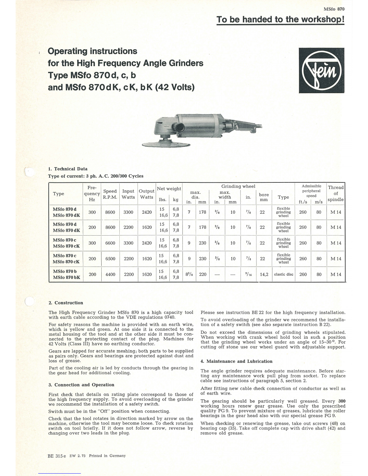
Operating instructions
for the High Frequency Angle Grinders
Type MSfo
870d,
c, b
and MSfo
870dK,
cK,
bK
(42
Volts)
1. Technical
Data
Type
of
current: 3 ph.
A.
C. 200/300
Cycles
Fre-
Grinding
wheel
Admissib
le
Thread
Speed
Input
Output
Net
weight
I I I I
pe
ripheral
qu~~cy
R.P.M.
Watts
Watts
lbs. I
kg
in~~:~m
in~F~m
in.
~;;
I
Type
ft
./
ssp
~
e~/s
spi~~le
1
------------+------+--
----~-----r
----~----+----+
----T-
---T
----
~
-----r----+-
----+-------
~--------
~~
----
---
Type
~~::
:~~:K
I 300 I 8600 I 3300 I 2420 I
!~.
6
~
~:~
I 7 1 178 1 3
/s
110 I 7
/s
122 I
:~i~!~~
I 260 I 80 I M
14
--
----
------
T-----
~
--
-
----
:
------T-----~--~----
~------
--
:
I 200 I 8600 I 2200 11620 I
!~.
6
~
~:~
I 7 1 178 1
3fs
I 10 I 7/s 122 I
:~i~!~~
I 260 I 80 I M
14
MSfo B70d
MSfo B70dK
MSfo
B70c
I
300
I 6600 I 3300 I 2420 11
1
:61
~:~
I 9
123
0 I
3fs
I 10 I 7/s 122 I
i~i~!~~
I 260 I 80 I M 14
MSfo B70cK
MSfo B70c I 200 I 6500 I 2200
11620
I
!~.
6
~
~:~
I 9 1230 I 3/s I 10 I 7
/s
122 I
:~i~!~~
I 260 I 80 I M
14
MSio
B70cK
MSfo
870b
MSfo
870bK
I 200 I 4400 I 2200
11620
I
!~.
6
~
~
:
~
18
5/a 1220 I -- I -- I 9
/,6
114,2 I
elastic
di
sc
I 260 I 80 I M
14
~--------~----~--~----~----~--~--~--~--~----~--~--~
2.
Construction
The
High
Frequency
Grinder
MSfo
870
is
a
high
capacity
tool
with
earth
cable
according
to
the
VDE
regulations
0740.
For
safety
reasons
the
machine
is
provided
with
an
earth
wire,
which
is
yellow
and
green.
At
one
side
it
is
connected
to
the
metal
housing
of
the
tool
and
at
the
other
side
it
must
be
con-
nected
to
the
protecting
contact
of
the
plug
.
Machines
for
42
Volts
(Class III)
have
no
earthing
conductor.
Gears
are
lapped
for
accurate
meshing;
both
parts
to
be
supplied
as
pairs
only.
Gears
and
bearings
are
protected
against
dust
and
loss
of
grease.
Part
of
the
cooling
air
is
led
by
conducts
through
the
gearing
in
the
gear
head
for
additional
cooling.
3.
Connection
and
Operation
First
check
that
details
on
rating
plate
correspond
to
those
of
the
high
frequency
supply.
To
avoid
overloading
of
the
grinder
we
recommend
the
installation
of
a
safety
switch.
Switch
must
be
in
the
"Off"
position
when
connecting.
Check
that
the
tool
rotates
in
direction
marked
by
arrow
on
the
machine,
otherwise
the
tool
may
become
loos
e.
To
check
rota
tion
switch
on
tool
briefly
.
If
it
does
not
follow
arrow,
reverse
by
changing
over
two
lead
s
in
the
plug.
BE
315 e
EW
2. 73
Printed
in
Germany
Please
see
instruction
BE
22
for
the
high
fr
eq
uency
installation
.
To
avoid
overloading
of
the
gri
nder
we
recommend
the
installa-
tion
of
a
safety
switch
(see
also
separate
inst
ruction
B 22).
Do
not
exceed
the
dimensions
of
grinding
wheels
stipulat
ed.
When
wo
r
king
with
crank
wheel
hold
tool
in
such
a
position
that
the
grinding
wheel
wo
r
ks
under
an
angle
of
15
-
30
°.
For
cutting
off
stone
use
our
wheel
guard
with
adjus
t
able
support
.
4.
Maintenance
and
Lubrication
The
ang
le
grinder
require
s
adequate
main
te
n
ance.
Before
star-
ting
any
maintenance
work
pull
plug
from
socke
t. To
replac
e
cable
see
instru
ct
ions
.
of
pa
ragr
aph
5,
sectio
n
2.
After
fitting
new
cable
check
con
nection
of
co
nductor
as
well
as
of
earth
wire.
The
gearing
should
be
particularly
well
greased.
E
ve
ry
300
working
hours
renew
gear
grease.
Use
only
the
prescribed
qualit
y FG 9.
To
prevent
mi
xture
of
greases
,
lubricate
the
roller
bearings
in
the
gear
head
also
with
our
special
grease
FG
9.
When
checki
ng
or
ren
ewing
t
he
grease,
take
out
sc
r
ews
(48)
on
bearing
cap
(3
5)
.
Take
of
f
complete
cap
with
drive
s
haft
(42)
and
remove
old
grease.

32
42
-~
---
---
--
45
-
__
43
- -_
44
----
46
-
-----
\
107
67 68
69
70
80
81
92 93 96
~
\
\
\
\
95
I
:
\
102
m
I
I
u)~
l~l.)i
,,l,
'11'?&;;;,
-;;-~nl
,,
\
',
,___
I : I I \ \
~
38
39
( ,-
--
(
~
'
------------
f--
-----
1
i
~
:
L:
~
~
-
-
~
~
-\
\
~-
708
78
I
i I
) j
79
I\ \
71
72
73
77
~
101
100
I
I
'
97
MSfo
870 d, c,
b,
200Hz,
111-265 V
MSfo
870 d, c,
300Hz,
150-265 V

( ·
---
- - -- --
--
--
------------------
-
91
I
I
104
91a
!!Ba
102
103
!
Dismantling
the
machines
of
these
types:
1.
Remove
grinding
wheel
and
safety
guard.
a
a
a
2.
Unscrew
fillister
screw
(101),
remove
control
lever
(100)
and
a
felt
ring
(99).
3.
Unscrew
screws
(102)
and
(98).
Push
away
the
handle
(90).
Clamp
off
the
cable
(93)
from
the
switch
(97)
.
Remove
the
cable
clamping
bridge
(95)
after
unscrewing
the
screws
(96).
Tak
e
off
handle
with
ca
bl
e.
4.
Unscrew
screws
(98 a),
take
off
switch
(97)
with
angle
(94).
After
unscrewing
the
screws
(73),
take
off
the
fan
housing
(69).
Then
see
§ 5 (4-8).
In
these
machines:
MSfo
870 dK, cK, bK, 200
Hz,
42 V
MSfo
870 dK, cK, 300 Hz, 42 V
and
MSfo
870 d,
c,
300Hz,
43-71 V
the
following
parts
are
different:
Part
Order
>.
Description
.....
No
Reference
a
73
SR
33-M6x!OO 3
cylindrical
scre
ws
90, 91,
GH
4-89-6 1
handle
assembled
with
fan
housing
94-103
and
switch
60 A
for
MSfo
870 dK,
cK
, bK,
200Hz,
42 V
and
for
MSfo
870 dK,
cK
,
300Hz,
42 V
90-91a
GH
4-89-2 1
handle
assembled
with
fan
housing
94-104
and
switch
60 A
for
MSfo
870
d,
c,
300Hz,
43-71 V
90-91
GH4-89
-5 1
handl
e
with
fan
housing
for
MSfo
870 dK, cK,
bK
, 200 Hz, 42 V
and
for
MSfo
870 dK, cK,
300Hz,
42V
90-91a
GH
4-89-1 1
handle
with
fan
housing
for
MSfo
870 d, c,
300H
z, 43-71 V
91a
MZ
37-29 1 eart
hing
rivet
(not
by
42
V)
92 .
JS
13-95 1
cable
protecting
sleeve
93 EZ 6-60 1 ca
ble
for
200/300 Hz, 42 V
93 EZ 6-158 1 ca
ble
for
300H
z, 43-71 V
94
BF
29-135-1 1
angle
95
PT
31
-
31
2
cable
clamping
bridge
96 SR 2-M5x18 2 cy
lindrical
screws
with
slot
97 EZ 1-82 1
sw
i
tch
60 A
98
SR6-M4x15
2
countersunk
screw
with
slot
98a
SR 2-M4x25 2 cy
lindrical
screw
99
DJ
1-79 1 fe
lt
gashet
100
SA
5-39 1
control
lever
101
SR3
-
M6
x10 1
fillister
scr
ew
with
sl
ot
102
SR33-M5x80
4
so
c
ket
head
cap
screw
103
PT
5d-M5
4
securing
plate
104
SR3-M5x8
1
earthing
screw
(not
by
42
V)

(
b
b
b
b
b
b
b
b
b
b
b
b
b
b
b
b
b
Component Parts
Part
Order
>-
Description
No.
Reference
a
1
MK3-114-1
1) 1
motor
housing,
assembled
for
MSfo
870
d, c,
b,
200Hz
,
111-265 v
for
MSfo
870
d, c,
300Hz
,
150-265 v
1
MK3-114-2
1) 1
motor
housing,
assembled
for
MSfo
870 d, c,
300Hz,
111-149 v
1
MK
3-114-31) 1
motor
housing,
assembled
for
MSfo
870 dK, cK,
bK,
200 Hz,
42 v
for
MSfo
870
dK, cK,
300Hz,
42 v
for
MSfo
870
d, c,
300Hz,
43-71 v
1
MK
3-114-4
1) 1
motor
housing,
assembled
for
MSfo
870
d, c,
b,
200
Hz,
43-110 v
for
MSfo
870 d, c, 300
Hz,
72-110 v
2-4
WL
8-30-1 1
rotor,
mounted
21-50
GH
6-63
-1
1
gear
housing,
assembled
for
MSfo
870 d, dK/300
Hz
21
-50
GH6-63-2
1
gear
housing,
assembled
for
MSfo
870 d, dK/200
Hz
21-50
GH
6-63-3 1
gear
housing,
assembled
for
MSfo
870 c, cK/300
Hz
MSfo
870
b,
bK/200
Hz
21-50
GH6
-63-4 1
gear
housing,
assembled
for
MSfo
870 c, cK/200
Hz
21
GH6-63
1
gear
housing
22 LK 16-52 1
ball
bearing
23
PT
11-64 1
cove
r
plate
24
DJ
1-75 1
fe
lt
ring
25
PT
36-25 1
flange
26
SR
2b-M5x20
3
cylindrical
screws
27
RJ
24-29
washer
for
bevel
pinion
(as
need
ed
)
28 BF 21-4x4x14 1
fitting
ke
y
292) ZR 13-88 1
bevel
pinion,
25
teeth
MSfo
870 d,
dK
300
Hz
292)
ZR
13-85 1
bevel
pinion,
31
teeth
MSfo
870 d, dK/200
Hz
292) ZR 13-87 1
bevel
pinion,
18
teeth
MSfo
870 c, cK/300
Hz;
b,
bK
/200
Hz
292) ZR 13-86 1
bevel
pinion,
25
teeth
MSfo
870 c, cK/200
Hz
303) BU 1-240 1
sleeve
31
PT
1-M8
1
disc
32
MR
19-1 1
nut
33 LK 6-24 1
ball
bearing
34
RJ
16-20 1
securing
ring
35
PT
19-55 1
bearing
plate
36 I
PT
11-66 1
cover
plate
37
DJ
1-49 1
felt
ring
38
RJ
27a-40x20,2 1
Nilos
ring
39 LK 16-25 1
ball
bearing
40
PT
16-58 1
flang
e
41
SR
2b-M4x12
3
cylindrical
screws
42
WB
6-102 1
driving
s
haft
43 BF 21-5x5x16 1
fitting
key
442)
ZR
14-133 1 b
eve
l
gear,
52
teeth
MSfo
870 d, dK/300
Hz
442) ZR 14-130 1
bevel
gear,
43
teeth
MSfo
870
d,
dK/200
Hz
442)
ZR
14-132 1
bev
el
gear,
49
teeth
MSfo
870 c, cK/300
Hz;
b,
bK/200
Hz
442) ZR 14-131 1
bevel
gear,
46
teeth
MSfo
870 c, cK/200
Hz
45 RJ 29a
-1
6x0,6 1
Seeger
circlip
46
RJ
24-68
washer
for
be
aring
plate
(as
n
ee
ded)
1)
When
ordering,
please
state
type
,
voltage
and
frequency
2)
Parts
29
and
44
are
lapped
together
and
are
supplied
only
by
pairs
b
b
b
a
a
a
b
b
b
Part
Order
>-
Description
.,_,
No
.
Reference
a
47
DJ
12-2 1
ri
nq
48
SR33-M5x20
4
hexagon
socket
sc
rew
49
DJ
11-5x9 4
sealing
ring
50
JS
20-20 1
plastic
plug
61
GH
7-61 1
bearing
housing
62 BU 1-237 1
cover
63 LK 16-38 1
ball
bearing
64
PT
8-207 1
disc
64a
RJ 27i-12x28,1 1
Nilos
ring
65 BF 21-3x3x8 1
fitting
key
66 FL 1-116 1
fa
n
67
PT
1-M8 1
disc
68
MR
19-1 1
hexagon
socket
screw
69
GH7-60
1
fa
n
housing
70
PT
27-49 1
cover
71
SR
33-M6xll0 3
socke
t
head
cap
screw
72
PT5d-M6
3
securing
plate
73
SR3-M4x8
1
earthing
screw
74
SR33-M5x25
4
soc
ke
t
head
cap
screw
75
PT
5d-M5
4
securing
plat
e
76
SR33-M5x35
4
soc
ke
t
head
cap
screw
77
PT
5d
-M5 4
securing
plate
80
JS
8-56 1
insu
lating
plate
81
JS
13-122 1
insu
lating
hose
82
DJ
5-49 1
packing
92-101
GH
4-67-9 1
handle
assembled
with
switch
16 A
92
GH4
-67 1
han
dle
93 EZ 1-64 1
sw
itch
16 A
94
PT
31-21 1
cable
clamping
bridge
95 SR 3-M3,5x15 2 fil
liste
r
screw
96
SR
2-M3,5x10 2
cylindrical
screw
97
DJ
1-52 1
felt
ring
98
SA
5-62 1
control
lever
99 SR
3-M3x15
1
fillister
screw
100 EZ 19-50 1
connection
cable
101
DJ
5-42 1
sealing
plate
102 EZ 6-153 1
cable
for
200Hz,
111-265
V,
300Hz,
150-265 V
103 JS 13-95 1
cable
protecting
sleeve
Accessories
105 M 10-70-1 1
safety
guard
assemb
le
d
to
MSfo
870 d,
dK
; 200/
300
Hz
105 M 10-71-1 1
safety
guard
assembled
to
MSfo
870 c,
cK;
200/
300
Hz
106
M8
-65 1 fl
ange
for
grinding
wheel
inside
4)
107
M8
-52 1
flange
for
grinding
whee
l
outside
4)
108
MZ
19-32 1
side
handl
e
Z 7-
SW
17 1
wrench
z 10-10 1
hexago
n
socket
screw
wre
nch
(M
5)
z 10-11 1
hexagon
socket
screw
wrench
(M6)
z 13-22 1
peg
spanner
MZ
60-3/FG9 1
tube
of
gear
grea
se
MZ
60-5/FK5 1
tube
of
ball
b
earing
g
rea
se
3)
Not
by
MSfo
870 d,
dK
, c, cK/200
Hz
4)
Not
by
MSfo
870 b,
bK

1 16 A
:
ide
4)
tside
4)
1 (M5)
1 (M6)
69
85
97
94
97
90
99
73
77 76
86
72 89 92
707
700 98
Dismantling
th
e
machines
of
these
types:
1.
Unscrew
scr
ew (96),
take
off
switch
grip
(95).
2.
Unscrew
screws
(73, 76),
take
off
h
and
le
(115).
Unscrew
screws
(101)
and
take
off
clamping
clips.
The
cable
can
be
pulled
out
after
un
screwing
switch
screws
and
the
ear
thing
a
b
a
screw
(72)
through
the
protecting
sleeve
(117). a
3.
Unscrew
4
screws
(70),
remove
switch
plate
(85)
and
fan
a
housing
(69).
Then
see
§ 5 (4-8).
721
120
In
th
ese
machines
:
MSfo 870 d,
c,
b,
200Hz,
43-110 V
an
d MSfo 870 d,
c,
300Hz,
72-149 V
the
following
parts
are
di
fferent:
Part
Order
:>.
D
esc
ription
No
Reference
0
69
GH7-70
1
fa
n ho
using
70
SR
33-M6x110 3
socket
head
cap
screw
71
PT
5d-M6
3
securing
plate
72
SR3-M5x8
1
earthing
screw
73
PT
5d-M6
3
securing
plate
76
SR33-M6x55
2
socket
head
cap
screw
77
SR
33-M6x15 1
socket
head
cap
screw
85-101
PT
33-21-2 1 switch
plate,
assembled
with
switch
25
A
85-91
PT
33-21-1 1 switch
plate,
assembled
92 EZ 1-54 1
switch
25
A
94
SR3-M4x8
3
fillister
screw
95
SA
5-38 1
switch
grip
96
SR3-M4x6
1
fillister
screw
97
DJ
1-46 1
felt
ring
98
PT
31-21 1
clamping
clip
99
PT
31-23 1
clamping
clip
100
PT
6-M3,5 2
sp
ri
ng
was
h
er
101
SR3-M3,5x25
2 filli
ster
screw
115-
GH
4-60-3 1
handle,
assembled
120
115
GH4-60
1
handle
116
JS
4-76 1
insu
lating
washer
117
JS
13-52 1
cab
le
protecting
sleeve
118
RJ
7-25 1
ho
lding
ring
11
9
SR6-M4
x6 2
fillister
h
ead
countersunk
screw
120
JS
16-15 1
rubber
sleeve
121 EZ 6-183 1
cab
le
for
200H
z, 43-72 V,
300Hz,
72-110 V
121 EZ 6-182 1 I
cable
for
200Hz,
73-110
V,
300Hz,
111-149V
I

Do
not
loose
washers
(46)
when
taking
off
or
regreasing
the
bea-
ring
plate.
These
are
essential
for
correct
meshing
of
the
bevel
gears.
Failure
to
replace
washers
may
cause
damage
to
gears.
To
avoid
overheating
and
to
ensure
adequate
lubrication
at
the
same
time
it
is
important
to
pack
the
gearing
with
the
grades
and
quantities
listened
in
the
table
below.
Type
of
Quantity
Order
I
Contents
Type
I
oz
I
grease
oz 1
Reference
g g
For
gearings
MSfo
870 d,
FG9
3 85 I
MZ
60-3/FG 9 3,2 1 90
dK
200Hz,
MSfo 870 c,
cK
200Hz
MSfo 870 c,
FG9
2,6 80 MZ 60-4/FG 9 6 180
cK
300Hz,
MSfo 870 b,
bK
200Hz,
MSfo
870 d,
dK
300Hz
For
ball
bearings
MSfo
870 d, c, b
FK5
MZ
60-5/FK5 0,18 5
MSfo
870 dK, cK,
bK
for
ball
approx.
'h
bearing,
part
63
of
the
MSfo
870 d, c, b
FG9
space
MZ
60-3/FG 9 3,2 90
MSfo
870 dK, cK,
bK
for
anti-
between
friction inner and
bearing
out
er
ring
part
33,
22
and
39
Bulk
grease
supplies
are
packed
in
tins.
After
every
900
working
hours,
the
machine
should
be
com-
pletely
dismantled
as
described
under
part
5,
and
all
parts
must
be
cleaned
thoroughly.
Rinse
ball
bearings
in
clean
solvent,
th
en
pack
them
with
fresh
grease
about
one
third
according
to
the
table.
No
claims
can
be
entertained
for
damage
due
to
negligent
main-
tenance
and
inadequate
lubrication.
5. Dismantling
Tool
should
only
be
taken
apart
by
an
expert
,
working
in
the
following
sequence:
For
the
types:
MSfo
870 d, c, b, 300 Hz, 150-265 V
and
200 Hz,
111-256 v.
1.
Remove
grinding
wheel
and
wheel
guard.
2.
Unscrew
the
screws
(99)
and
take
off
the
lever
(98).
Take
off
the
screws
(76)
and
push
away
the
handle
(92).
After
clamp-
ing
off
the
cable
the
switch
can
be
removed
.
3.
Unscrew
the
screws
(71),
pull
out
the
cover
(70)
and
take
off
the
fan
housing
(69).
4.
Unscrew
nut
(68)
and
take
away
the
wing
fan
(66)
with
the
disc
(67),
the
fitting
key
(65)
and
the
disc
(64).
5.
Take
away
the
screws
(48)
and
take
away
the
bearing
plate
(35)
with
the
input
shaft
(42)
and
bevel
gear
(44).
Pay
attention
to
the
washers
(46)
and
ring
(47)!
6.
After
unscrewing
screws
(74),
pull
gear
housing
(21)
with
rotor
(2)
out
of
the
motor
housing
(1
).
Unscrew
hexagon
nut
(32)
from
rotor
shaft
(2),
then
remove
washer
(31),
bevel
pinion
(29),
fitting
key
(28),
washer
(27).
The
rotor
(2)
can
now
be
pulled
out
of
the
gear
housing
(21).
7.
Unscrew
screws
(26),
take
off
flange
(25);
remove
cover
pla
te
(23)
and
felt
ring
(24).
8.
The
internal
ring
of
the
needle
bearing
(from
the
part
(33))
must
be
taken
out
of
the
driving
shaft
(42),
remove
the
Seeger
circlip
(45)
take
away
the
bevel
gear
(
44)
and
the
fitting
key
(43).
Unscrew
screws
(41),
remove
flange
(40)
and
draw
out
driving
shaft
(42)
with
ball
bearing
(39)
out
of
the
bearing
plate
(35).
Re-assemble
in
reverse
sequence
.
When
refitting
pinion
and
bearing
plate,
please,
bear
in
mind
that
wash
e
rs
(27, 46)
are
to
be
placed
in
their
right
places
as
they
are
needed
for
accurate
adjustment
of
the
gearing
.
When
fitting
bearing
plate
check t
hat
(
bevel
gear
wheels
mesh
accurately.
For
this
purpose
turn
drive
shaft
(42)
slightly;
only
then
,
fasten
screws
(48)
.
I
Type
I
Tube
I
Plate
I
Dismantling
device
MSfo
870 c,
200Hz
zso8-2 zso9-47
zso
11-14-1
300Hz
zso8-2 zso9-48
zso
11-10-1
MSfo
870 d,
200Hz
zso8-2 zso9-46
zso
11- 8-1
300Hz
zso8-2 zso9-49
zso
11-14-1
6.
Repair
and
spare parts
We
recommend
our
FEIN
Service
Stations
to
carry
out
all
over-
haul
and
repair
work
quickly
and
expertly.
We
deliver
special
tools
to
carry
out
repairs.
The
base
tube
and
the
two
-
part
dismantling
plate
are
used
to
take
off
the
bevel
gear
(44)
and
t
he
dismantling
dev
i
ce
to
take
off
the
bevel
pinion
(29).
When
ord
e
ring
spare
parts,
please
quote
typ
e
and
se
r
ial
No
of
the
machine
as
well
as
Order
Reference
of
the
required
pa
rt
or
send
in
the
damaged
part.
We
draw
your
attention
to
the
need
to
carry
out
a
high
voltage
test
in
accordance
with
your
local
regulations
(or VDE
regu-
lation
0740)
before
taking
a
tool
into
service
after
any
repair
carried
out
by
your
own
staff.
(
This manual suits for next models
5
Table of contents
Other Fein Grinder manuals

Fein
Fein MSho 852 K User manual

Fein
Fein WSg 20-230 Quick start guide

Fein
Fein MSh 636-1 User manual

Fein
Fein WSg 20-180 User manual

Fein
Fein GRIT GICS User manual

Fein
Fein WSg 20-180 User manual

Fein
Fein WSg 20-180 User manual

Fein
Fein WSG 8-115 A Setup guide

Fein
Fein WSG10-115T User manual

Fein
Fein GRIT Belt Grinder User manual

Fein
Fein GRIT GXC Series User manual

Fein
Fein MSfo870-1d User manual

Fein
Fein GSZ8-280P Setup guide

Fein
Fein KS10-38E User manual

Fein
Fein CG13-125V User manual

Fein
Fein MShy 664 User manual

Fein
Fein MSfo 880-ld User manual

Fein
Fein AGSZ18-280BL User manual

Fein
Fein Grit GIXS Series User manual

Fein
Fein WSG 15-125PSQ User manual