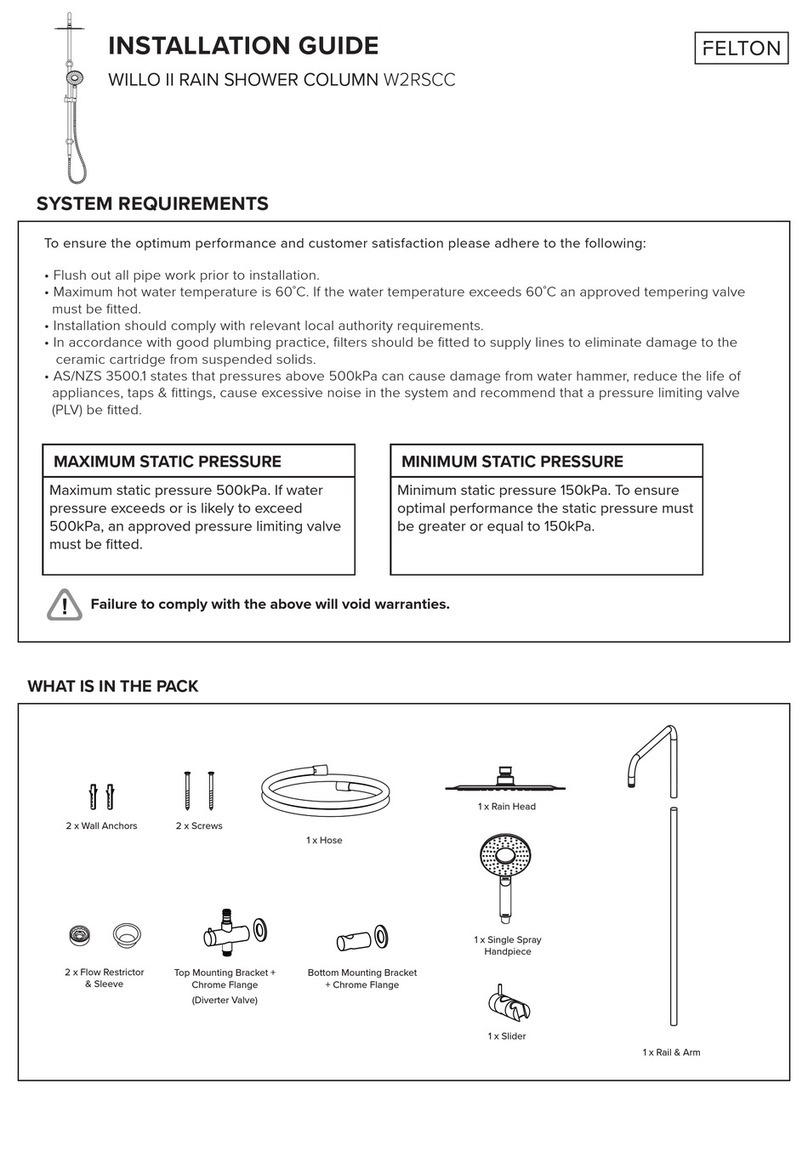
Body
Rose
Assembly
pips
45 mm
from back
of mixer
to front of
shower
wall Lining.
64 mm
Height
of
recess.
Installation Instructions
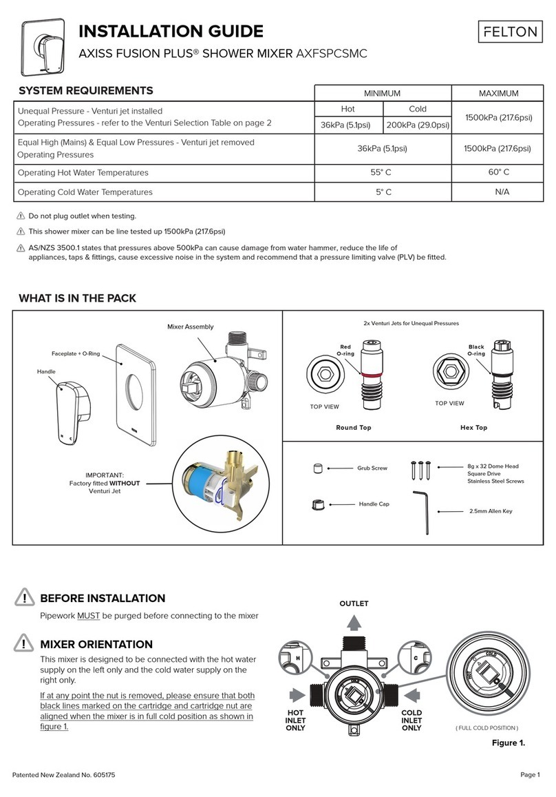
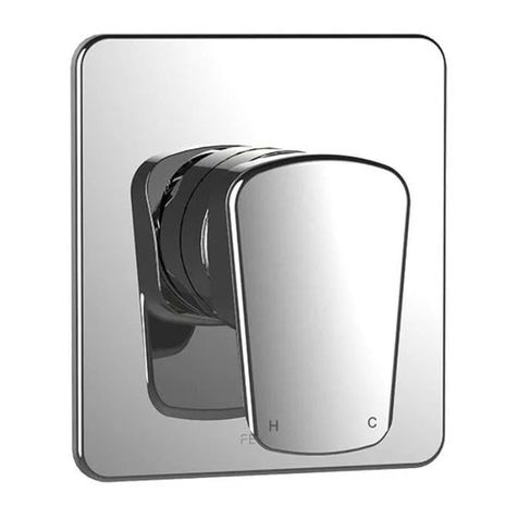
FELTONMIX®Shower Valves
Types U, E and H
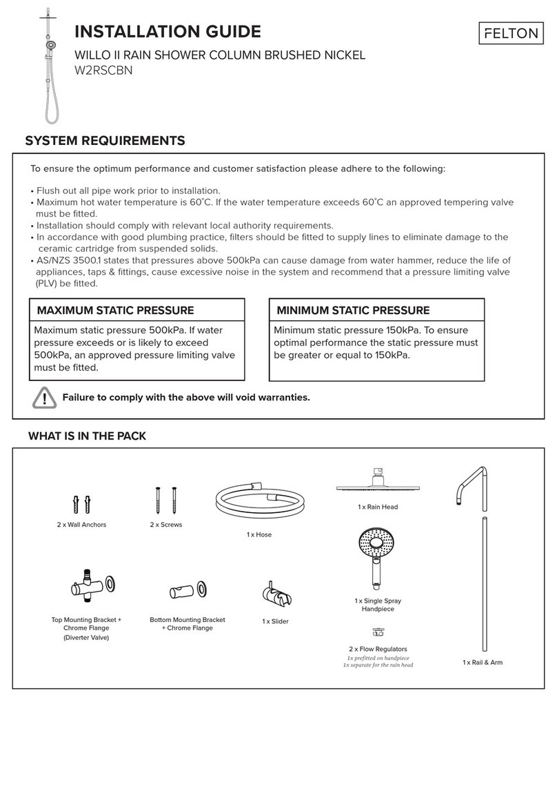
1. Provide a stud or other suitable fixing in the
shower wall on which to mount the shower valve
Shower head at about eye level (between 1.5 and
1.8 metres) is a good guide. Ensure distance from
mounting face to front of wall lining is 45mm.
2. Flush out pipework. Mount shower valve
assembly and secure with two wood screws
provided. It is important that the pipes which are
now connected directly to the isolator valves on
each side of the shower valve assembly line up
correctly with the isolators and do not place any
unnecessary strain on the valve assembly. Ensure
isolators are open, (turn anticlockwise).
Do not apply heat to pipes connected to the mixer
as internal damage may occur.
Note: When tightening crox nuts it is important to
hold the hexagon face to prevent any strain on the
isolator. Do not attempt to tighten or remove
the brass nipple from the isolator. This has
been installed with correct pre-loading at the
factory and any alteration may cause damage
to the isolator.
3. Cut an access hole in the wallboard to suit the
shapeof the wallplate usingthe template provided.
4. Position the wallplate over the valve outlet and
fit the two 11/8x 7 screws provided through each
wallplate slot and into the valve body lugs. Tighten
screws alternately until wallplate is firmly clamped
to the wall.
Warning:
Do not overtighten. Light pressure is sufficient
to clampthe wallplate firmly.
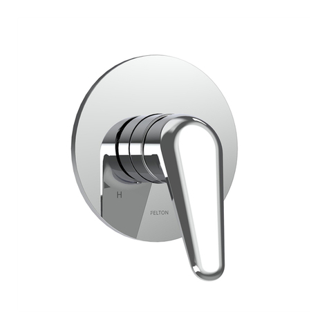
5. Rotate slotted sleeve on valve body
(projecting from central hole of wallplate
anticlockwise and fit handle to sleeve,
locating at the 4 o’clock position. Handle
should recess into the wallplate and match
its contours.Ensure that handle has about
10 mm of engagement.
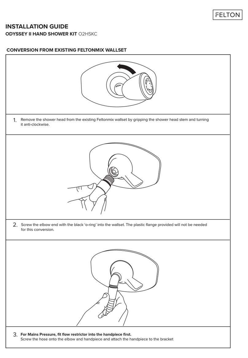
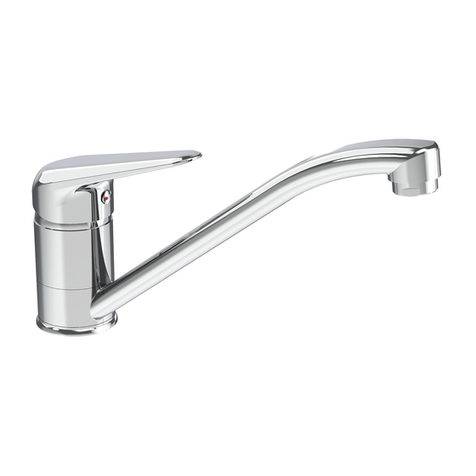
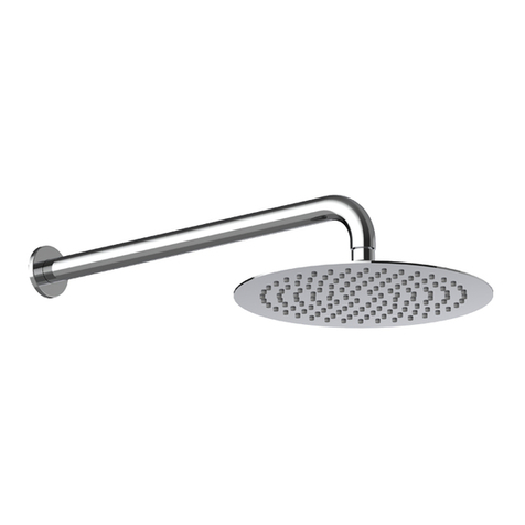
6. Screw showerhead into valve assembly
until full home. If necessary unscrew the
showerhead part of a turn to bring it to the
correct position. The O-ring seal fitted to the
showerhead stem will ensure a watertight
seal. Tape or hemp on the thread is not
necessary or desirable.
7. CHECK OPERATION. When installed check
that the handle swins from right to left from
OFF to HOT.Total movement is about 130°.
SHOWER HEAD
Insufficient Water Flow:
Check that the correct model (Type U,
Type E or Type H) has been installed for
the supply conditions. Check filters for
foreign matter.
Insufficient Hot Water:
Check that isolators are fully open
(unscrewed anticlockwise) Check that
sufficient water pressure is reaching the
valve. A minimum of 20 kPa (3 p.s.i.) flow
pressure is recommended.
Inadequate hot water temperature and/or
flow may also be experienced if a
tempering valve is fitted and is not
installed strictly in accordance with the
manufacturer’s instructions.
Valve does not shut off properly:
Check seals.
Water leaks from behind handle:
If water is leaking from under slotted
sleeve when shower is on it will be
necessary to replace O-ring seals on rotor.
(see a/so Service Notes)
To protect your investment, use only Genuine Feltonmix Spare Parts. Substitutes
may damage the Feltonmix product. Authorised parts carry the description
GENUINE SPARE PARTS MANUFACTURED BY FELTONMIX LTD, AUCKLAND, N.Z.
TROUBLE SHOOTING
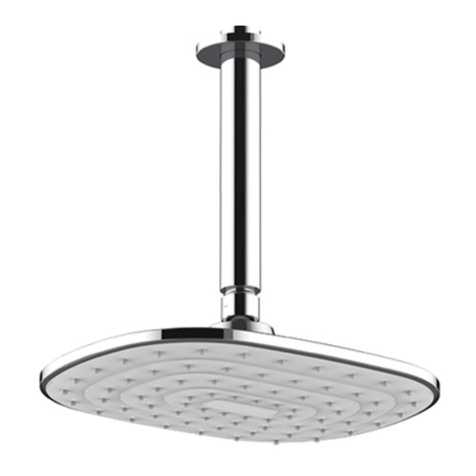
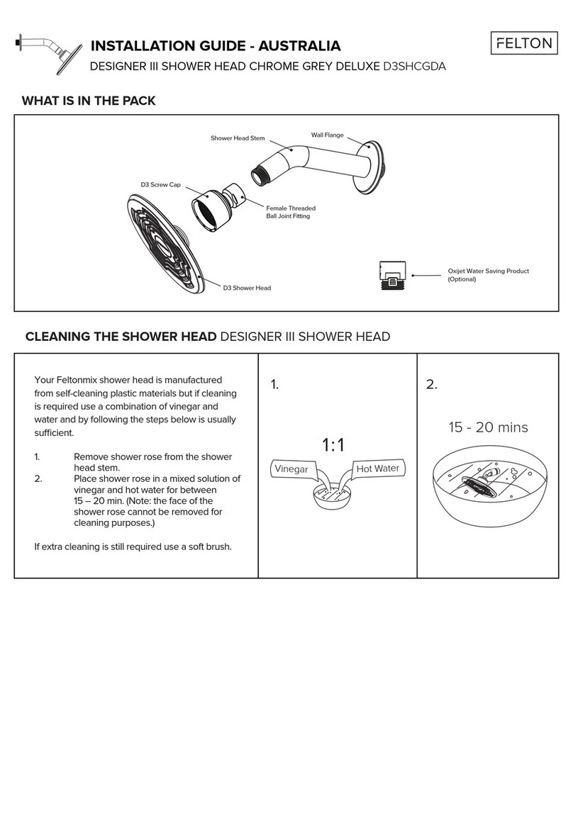
Your Feltonmix shower head is manufactured
from self-cleaning plastic materials and cleaning
with a soft nylon brush and bathroom cleaners is
usually sufficient.
If dismantling is required, insert the two leg’s
of the Feltonmix spanner into the face
of the rose. Turn the rose approximately
thirty degrees and withdraw it from the
shower head body.
When assembling ensure that the sharp
outer edge of thesoft spray ring is
located at the front edge of its support
ring. Align the assemblypips on the front face
of the rose and lipof the body. Pushthem together
until they click twice.
Manufactured by FELTON INDUSTRIES LTD
Freephone 0800 PH FELTON (0800 743 358)
Free Fax 0800 FAX FELTON (0800 329 335)
www.felton.co.nz


