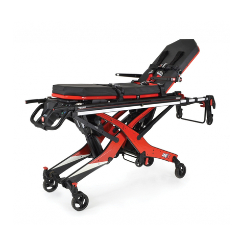
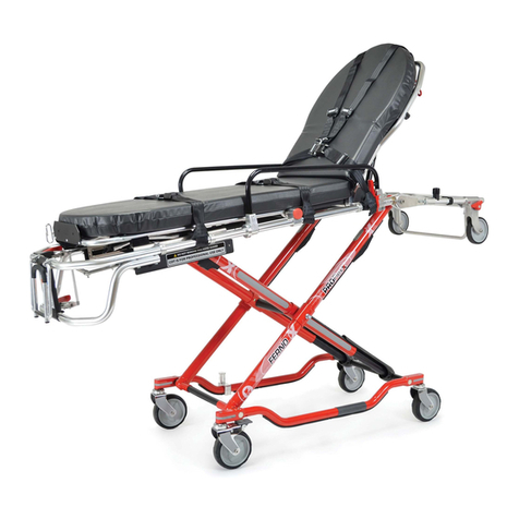
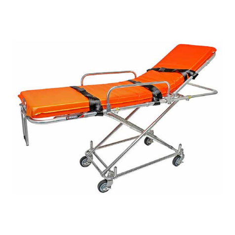
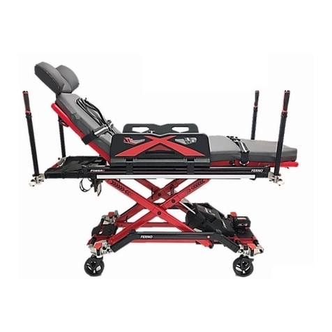
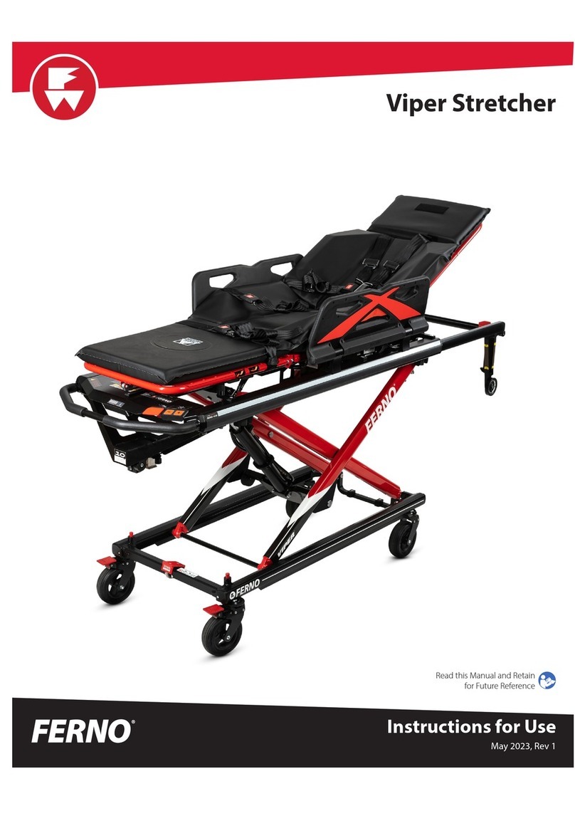
Ferno POWERFlexx User manual

POWERFlexx™
Hydraulic Cot
May 2005 GLO
Users’ Manual
Pub. No. 234-3310-01

2© Ferno-Washington, Inc. 234-3310-01 May 2005
POWERFlexx™
Disclaimer
This manual contains general instructions for the use, operation and
care of this product. The instructions are not all-inclusive. Safe and proper
use of this product is solely at the discretion of the user. Safety
information is included as a service to the user.All other safety measures
taken by the user should be within and under consideration of applicable
regulations. It is recommended that training on the proper use of this
product be provided before using this product in an actual situation.
Retain this manual for future reference. Include it with the product in
the event of transfer to new users. Additional free copies are available
upon request from Customer Relations.
Proprietary Notice
The information disclosed in this manual is the property of Ferno-
Washington, Inc., Wilmington, Ohio, USA. Ferno-Washington, Inc.
reserves all patent rights, proprietary design rights, manufacturing
rights, reproduction use rights, and sales use rights thereto, and to any
article disclosed therein except to the extent those rights are expressly
granted to others or where not applicable to vendor proprietary parts.
Ferno-Washington, Inc.
70 Weil Way
Wilmington, OH 45177-9371 U.S.A.
© Copyright Ferno-Washington, Inc. All Rights Reserved.
Telephone (U.S.A. and Canada) ......... 1.877.733.0911
Telephone (Worldwide) ................... +1.937.382.1451
Fax (United States) ............................. 1.937.382.1191
Fax (Outside U.S.A.) ...................... +1.937.382.6569
Internet ............................................... www.ferno.com

POWERFlexx™
© Ferno-Washington, Inc. 234-3310-01 May 2005 3
TABLE OF CONTENTS
Page
Section
1 - Safety Information ................................................ 5-6
1.1 Warning ............................................................ 5
1.2 Important .......................................................... 5
1.3 Bloodborne Disease Notice ............................. 5
1.4 Cot and Fastener Compatibility ....................... 5
1.5 Safety and Instruction Labels ........................... 6
2 - Operator Skills and Training .................................. 7
2.1 Skills ................................................................. 7
2.2 Training ............................................................ 7
2.3 Height and Strength Considerations ................. 7
3 - About the Cot ...................................................... 8-10
3.1 Cot Description ................................................ 8
3.2 General Specifications ..................................... 8
3.3 Components ...................................................... 9
3.4 Cot Height ...................................................... 10
4 - Setup and Installation....................................... 11-13
4.1 Attach the Restraints and Mattress.................. 11
4.2 Install the Safety Hook ............................. 11, 12
4.3 Update Your Model 175 Fastener .................. 13
5 - Using the Hydraulic Power System ................. 14-17
5.1 General Guidelines ......................................... 14
5.2 Main Power Switch ........................................ 14
5.3 Touch Pad Controls ........................................ 15
5.4 Battery Charge Indicator ................................ 15
5.5 Manual Mode ................................................. 16
5.6 Battery Charger .............................................. 17
5.7 Power Pack Module ....................................... 17
6 - Cot Features ........................................................ 18-23
6.1 Drop Frame .................................................... 18
6.2 Safety Bar Release Handle ............................. 19
6.3 Backrest .......................................................... 19
6.4 Sidearms ......................................................... 20
6.5 Shock Frame ................................................... 20
6.6 Adjustable Foot-End Lift Bar ........................ 21
6.7 Lead Handle ................................................... 22
6.8 Wheel Locks ................................................... 22
6.9 Patient Restraints ............................................ 23
6.10 Locking Mattress ............................................ 23
Page
Section
7 - Using the Cot ..................................................... 24-28
7.1 Before Placing the Cot in Service .................. 24
7.2 General Guidelines for Use ............................ 24
7.3 Changing Cot Height ...................................... 25
7.4 Transferring the Patient ................................... 26
7.5 Rolling the Cot ............................................... 27
7.6 Using Additional Help.................................... 28
8 - Loading and Unloading the Cot ........................ 29-32
8.1 Fastener Compatibility ................................... 29
8.2 Guidelines and Preparation ............................ 29
8.3 Loading the Cot .............................................. 30
8.4 Unloading the Cot .......................................... 31
8.5 One Operator Loading/Unloading
an Empty Cot .................................................. 31
8.6 Non-Powered Loading and Unloading .......... 32
9 - Maintenance ........................................................ 33-37
9.1 Maintenance Schedule ................................... 33
9.2 Disinfecting and Cleaning the Restraints ....... 33
9.3 Disinfecting and Cleaning the Mattress ......... 33
9.4 Disinfecting the Cot ....................................... 33
9.5 Cleaning the Cot ............................................. 34
9.6 Waxing the Cot ............................................... 34
9.7 Inspecting the Cot........................................... 34
9.8 Lubricating the Cot......................................... 35
9.9 Charging the Batteries .................................... 36
9.10 Adjusting the Tension Of the
Manual Mode Cable ....................................... 37
10 - Parts and Service .............................................. 38-39
10.1 Parts and Service - USA and Canada ............. 38
10.2 Parts and Service - Outside North America ... 38
10.3 Parts List ......................................................... 38
10.4 Parts Diagrams ............................................... 39
11 - Accessories and Related Products ........................ 40
12 - Limited Warranty .................................................. 41
13 - Ferno Customer Relations .................................... 41
Training Record............................................................. 42
Maintenance Record ..................................................... 43
4© Ferno-Washington, Inc. 234-3310-01 May 2005
POWERFlexx™
Safety and Instruction Labels ............................................ 6
Height and Strength Considerations .................................. 7
Components ....................................................................... 9
Cot Height ..................................................................... 10
Figure 1 - Safety Hook .................................................. 11
Figure 2 - Engaging the Safety Hook ............................ 11
Figure 3 - Safety Hook Placement ............................... 12
Figure 4 - Installing the Safety Hook ........................... 12
Figure 5 - Old-Style and New-Style Mounting Blocks 13
Figure 6 - Updated Antler Shown After Rear
Mounting Block & Turn-Knob Replaced .... 13
Figure 7 - Operators Maintain Grasp on Cot
During Hydraulic Operation ........................ 14
Figure 8 - Main Power Switch ..................................... 14
Figure 9 - Touch Pad Controls ..................................... 15
Figure 10 - Press Anywhere in the Colored Area
to Operate the Touch Pad ............................ 15
Figure 11 - Battery Charge Indicator ............................. 15
Figure 12 - Manual Mode Handle .................................. 16
Figure 13 - Using the Manual Mode Handle ................. 16
Figure 14 - Battery Charger ............................................ 17
Figure 15 - Cable Connections ....................................... 17
Figure 16 - Removing the Power Pack Module ............. 17
Figure 17 - Drop Frame Positions .................................. 18
Figure 18 - Adjusting the Drop Frame ........................... 18
Figure 19 - Safety Bar Release Handle .......................... 19
Figure 20 - Using the Backrest ....................................... 19
Figure 21 - Using the Sidearm ....................................... 20
Figure 22 - Lowering the Shock Frame .......................... 20
Figure 23 - Foot-End Lift Bar Positions ........................ 21
Figure 24 - Adjusting the Foot-End Hinges ................... 21
Figure 25 - Using the Lead Handle ................................ 22
Illustrations
Figure 26 - Wheel Lock.................................................. 22
Figure 27 - Restraints ..................................................... 23
Figure 28 - Attaching the Mattress ................................. 23
Figure 29 - Changing Cot Height ................................... 25
Figure 30 - Short Operators Using
Lower Lifting Positions ............................... 25
Figure 31 - Securing the Patient ..................................... 26
Figure 32 - Rolling the Cot............................................. 27
Figure 33 - Rolling the Cot............................................. 27
Using Additional Help ..................................................... 28
Figure 34 - Examples of Model 175
(Antler and Rail) Fasteners.......................... 29
Figure 35 - Cot Safety Bar on Safety Hook ................... 30
Figure 36 - Raising and Folding the Cot ........................ 30
Figure 37 - Loading the Cot ........................................... 30
Figure 38 - Unloading the Cot ........................................ 31
Figure 39 - Disengaging the Safety Bar ......................... 31
Figure 40 - One Operator With Empty Cot .................... 31
Figure 41- Manual Mode: Non-Powered Loading
or Unloading the Cot ................................... 32
Minimum Intervals for Maintenance ............................... 33
Lubrication Diagram ....................................................... 35
Figure 42 - Battery Charger ............................................ 36
Figure 43 - Charger Connected to
Power Pack Module On Cot ........................ 36
Figure 44 - Charger Connected to Power Pack .............. 36
Figure 45 - Proper Handle Function............................... 37
Figure 46 - Place a Chock On the Lower Frame ............ 37
Figure 47 - Manual Mode Adjustment Nuts................... 37
Parts Diagrams ................................................................ 39
Serial Number Location .................................................. 41

POWERFlexx™
© Ferno-Washington, Inc. 234-3310-01 May 2005 5
1 - SAFETY INFORMATION
Safety Information
Important
Before installing the safety hook, consult the
ambulance manufacturer about possible
interference with wiring and other elements
under the ambulance floor, and about the
ambulance warranty.
1.1 Warning
Warning notices indicate a potentially hazardous
situation which, if not avoided, could result in injury.
1.2 Important
Important notices emphasize important usage or
maintenance information.
1.3 Bloodborne Disease Notice
To reduce the risk of exposure to bloodborne diseases
such as HIV-1 and hepatitis when using the cot, follow
the disinfecting and cleaning instructions in this manual.
1.4 Cot and Fastener Compatibility
Combining different manufacturer’s products into a
“mixed-component” cot/cot fastener system can
increase the users’ risk of injury and damage. Ferno-
Washington, Inc. strongly recommends that only Ferno-
manufactured cots be used in Ferno-manufactured cot
fasteners, and that only Ferno-manufactured cot
fasteners be used for securing Ferno-manufactured cots
in ambulances.
ANY COMBINATION OF A FERNO COT OR COT
FASTENER WITH A NON-FERNO COT OR COT
FASTENER IS MISUSE OF THE FERNO PRODUCT.
Responsibility for the outcome of known, intentional
misuse rests squarely on the misuser.
Improper parts and service can cause injury.
Use only Ferno parts and Ferno-approved
service on the cot.
Modifying the cot can cause injury and damage.
Use the cot only as designed by Ferno.
Attaching improper items to the cot can
cause injury. Use only Ferno-approved items
on the cot.
WARNING
!
Untrained operators can cause injury or be
injured. Permit only trained personnel to
operate the cot.
Improper use can cause injury. Use the cot only
for the purpose described in this manual.
Failure to use the safety hook can cause injury.
Install and use the safety hook as described in
this manual.
Uncontrolled cot movement can cause injury
or cot damage. Support and control cot when
using manual mode.
Improper operation can cause injury. Operate
the cot only as described in this manual.
An unattended patient can be injured. Stay with
the patient at all times.
An unrestrained patient can fall off the cot and
be injured. Use restraints to secure the patient
on the cot.
Rolling the cot in the loading attitude can
increase the chance for the cot to tip. Roll the
cot only when the main frame is level.
Helpers can cause injury or be injured. Maintain
control of the cot, operate the controls, and
direct all helpers.
Helpers can be injured. Show helpers where to
grasp the cot to avoid pinch points.
Improper maintenance can cause injury.
Maintain the cot only as described in this
manual.
Improper adjustment of the manual mode cable
can lead to injury. Adjust the tension of the
manual mode cable when needed.
The cot can rapidly descend and cause injury
if manual mode is activated while you are
adjusting the manual-mode cable tension.
Place a chock on the lower frame and use
caution when adjusting cable tension.
WARNING
!

6© Ferno-Washington, Inc. 234-3310-01 May 2005
POWERFlexx™
1.5 Safety and Instruction Labels
Safety and instruction labels place important information from the users’ manual on the cot. Read and follow
label instructions. Replace worn or damaged labels immediately. See Parts and Service, page 38.
Safety Information
Label A (1 per cot) - Summary of instructions for safe
and proper operation of the cot.
Label D (1 per cot) - Indicates the
location of the control used to operate
the cot manually.
Label B and Label C
(6 total per cot) -
Indicates that fingers or
hands can be injured if
placed near areas of the
cot where these labels
are located.
Label E and Label F
(4 total per cot) -
Indicates that fingers or
hands can be injured if
placed near areas of the
cot where these labels
are located.
LABELS AFFIXEDTOTHE COT
LABELS AFFIXEDTOTHE POWER PACK
Label D (1) - Indicates Power Pack
contents and specifies service personnel.
Label B (1) - Indicates where to connect
the actuator cable to the power pack.
Label C (1) - Indicates where to connect
the charging cable to the power pack.
LabelA (1) - Indicates where to connect
the control-unit cable to the power pack.

POWERFlexx™
© Ferno-Washington, Inc. 234-3310-01 May 2005 7
Operator Skills and Training
2.3 Height and Strength Considerations
2 - OPERATOR SKILLS ANDTRAINING
2.1 Skills
Operators using the cot need:
a working knowledge of emergency patient-
handling procedures.
the ability to assist the patient.
a complete understanding of the procedures
described in this manual.
2.2 Training
Trainees need to:
follow a training program designed by their
training officer.
read this manual. For additional free users’
manuals, contact your Ferno distributor or Ferno
Customer Relations (page 41).
Untrained operators can cause injury or be
injured. Permit only trained personnel to
operate the cot.
WARNING
!
practice with the cot before using it in regular
service.
be tested on their understanding of the cot.
record their training information. A sample
training record sheet is provided on page 42.
The hydraulic power system of this cot eliminates the
need for an assistant operator to raise or lower the
undercarriage when the cot is in its powered mode. This
allows the assistant to stand with the control operator
and help lift and hold the weight of the cot.
Once the wheels are on the ground during unloading,
stop pressing the RAISE/UNLOAD touch pad.
When loading the cot, the control (foot-end) operator
must lift and hold the weight of the cot, patient, and
equipment until the cot legs have folded.
When unloading the cot, the control operator must lift
and hold the weight until all four wheels are on the ground.
Supporting this weight requires greater strength from
short operators than from tall operators, because short
operators must raise their arms higher in relation to
their shoulders. Use additional help as needed to lift
the load (see Using Additional Help, page 28).

8© Ferno-Washington, Inc. 234-3310-01 May 2005
POWERFlexx™
About the Cot
3 - ABOUTTHE COT
3.1 Cot Description
The POWERFlexx™Hydraulic Cot (referred to as the
cot in this manual) is an emergency patient-handling
device designed to transport a patient in a ground-based
ambulance.
The electronically-controlled, power-lift system helps
reduce the risk of back injury to medical service
personnel by hydraulically raising and lowering the cot.
The lift mode can be changed to manual when desired.
The cot is for professional use by a minimum of two
trained operators. It is designed for use with Ferno’s
Model 175 Series cot fasteners (not included).
The cot is shipped with a battery charger, plus a safety
hook, low-profile mounting block, and short turn-knob
for use with the fastener. Cot features include:
• Modular hydraulic actuator unit
• Modular power pack with electronic controls
• Manual mode control for non-powered use
• Touch-pad controls for easy raising and lowering
• Infinite height adjustment from 13 to 41 inches
• Loading at any height up to 33 inches
• Anodized tubing for clean hands and clothing
• Choice of colors
• Multipurpose drop frame
• Adjustable foot-end lift bar
• Adjustable pneumatic backrest
• Shock frame
• One-hand, swing-down sidearms
• Four 6-inch, swivel transport wheels, two with
wheel locks
• Set of patient restraints
• Foot-end lead handle
• Locking mattress AMBULANCE INFORMATION
The ambulance bumper extension must not exceed 14
inches. The patient compartment must have a level floor
large enough for the folded cot, and a Ferno®cot fastener
installed (not included). See Cot and Fastener
Compatibility, page 5.
The cot is for use with ambulances that meet the
requirements of Federal Ambulance Specification KKK-
A-1822. For information about the specification, contact:
Federal Supply Services, Specifications Section. Suite
8100. 470 E. L’Enfant Plaza, SW. Washington, DC 20407.
3.2 General Specifications
Bed Height Range*.................... 13-41 in/33-104 cm
Maximum Loading Height ................. 33 in (84 cm)
Length
Maximum ..................................... 83 in (211 cm)
Minimum ...................................... 61 in (155 cm)
Patient Surface .............................. 79 in (201 cm)
Width
Overall ............................................ 24 in (61 cm)
Patient Surface ................................ 16 in (41 cm)
Load Limit......................................... 700 lb (318 kg)
Control Unit .................................................. 24VDC
Charging Time ............................................... 3 hours
**Weight.............................................. 133 lb (60 kg)
* Bed height is the distance from the ground to the top
surface of the seat panel, at the longitudinal center of the
cot. Loading height is the distance from the ground to the
bottom of the loading wheel.
** Weight includes power pack but does not include
mattress or restraints.
General specifications are rounded to the nearest whole
number. Metric conversions are calculated before rounding
the English measurements. For more information, contact
Ferno Customer Relations (page 41) or your Ferno distributor.
Ferno reserves the right to change specifications without notice.
Improper use can cause injury. Use the cot
only for the purpose described in this
manual.
WARNING
!
LOAD LIMIT
Inspect the cot if the load
limit has been exceeded.
(See Inspecting the Cot,
page 34).
700 lb
318 kg

POWERFlexx™
© Ferno-Washington, Inc. 234-3310-01 May 2005 9
Loading
Wheel (2)Safety Bar
Release
Handle (2)
Backrest
Control Handle
HEAD END FOOT END
3.3 Components
About the Cot
24 VDC Power Pack Module
Shock Frame
6" Swivel
Wheel (4) Wheel
Lock (2)
Safety Bar
Swing-Down
Sidearm (2)
Drop Frame
Control Handle
Hydraulic
Actuator Unit
Control Panel
(see insets)
Control Panel - Top
Battery Charge
Indicator Power SwitchLead Handle
LOWER/LOAD
Touch Pad
RAISE/UNLOAD
Touch Pad
175 Fastener Post
Sidearm Release
Handle
• Safety Hook
• Low-Profile Mounting Block
• Short Turn-Knob
• Users’ Manual
• Set of Restraints
• Mattress
ALSO INCLUDED:
Control Panel - Bottom
Manual Mode Handle
Release for
Manual Mode
Handle
Battery Charger
Backrest
Shock Frame
Release Levers
Drop Frame

10 © Ferno-Washington, Inc. 234-3310-01 May 2005
POWERFlexx™
3.4 Cot Height
About the Cot
The cot can be loaded into ambulances with
floor heights up to 33 inches (84 cm).
Note: The cot is described as being in the
“loading attitude” when the cot is raised
to its highest level.
Note:Loading height is measured from the
ground to the bottom of the loading wheels.
Maximum Loading Height
33" (84 cm)
LOADING HEIGHT RANGE
Fully fold the cot to place it in an ambulance or to
transfer a patient from the ground onto the cot. The cot
can also be rolled in the fully folded position if needed.
12" (30 cm)
FULLY FOLDED POSITION
Transfer the patient to the cot, or roll the cot, with the
patient surface 12-30 inches (30-76 cm) above the
ground. Do not roll the cot at its highest level - rolling
the cot in a loading attitude can increase the chance
that the cot could become unbalanced and tip.
12-30"
(30-76 cm)
ROLLING-HEIGHT RANGE AND PATIENTTRANSFER RANGE

POWERFlexx™
© Ferno-Washington, Inc. 234-3310-01 May 2005 11
Setup and Installation
4 - SETUP AND INSTALLATION
4.2 Install the Safety Hook
The safety hook (Figure 1) provided with the cot is a
component of Ferno’s cot fastening system, and must
be installed on the ambulance floor.
The safety hook catches the cot safety bar (Figure 2) to
ensure that the cot remains secure inside the ambulance
while the operators raise or lower the undercarriage
during loading or unloading.
Installing the safety hook requires the skills of a
mechanic familiar with ambulance construction.
Before installing the safety hook, consult the ambulance
manufacturer about the location of wiring, oxygen or
fuel lines, and other elements under the ambulance
floor, and about the ambulance warranty.
HARDWARE NEEDED (NOT SUPPLIED)
2 ........................ 1/4in-20 flat-head machine screws*
2 .............................................................. flat washers
2 ............................................................ lock washers
2 ............................................................. ¼ in-20 nuts
*The machine screws must be long enough to pass
through the safety hook, patient compartment floor,
both washers, and still have at least two full threads
extending past the nut.
The hardware should be of at least SAE Grade 5 with
UNC-2 thread (or equivalent).
Important
Before installing the safety hook, consult the
ambulance manufacturer about possible
interference with wiring and other elements
under the ambulance floor, and about the
ambulance warranty.
4.1 Attach the Restraints and Mattress
Before placing the cot in service, attach the mattress and restraints (see page 23). Also see the restraint users’
manuals provided with the restraints. Keep the restraint instructions with this manual for future reference. For
additional, free manuals, contact Ferno Customer Relations (page 41).
Failure to use the safety hook can cause
injury. Install and use the safety hook as
described in this manual.
WARNING
!
Figure 2 - Engaging the Safety Hook
Safety Bar
(on cot)
Safety Hook
(on ambulance floor)
Figure 1 - Safety Hook
Hook
Rear Edge

12 © Ferno-Washington, Inc. 234-3310-01 May 2005
POWERFlexx™
Setup and Installation
POSITIONINGTHE SAFETY HOOK
Position the safety hook as close to the rear of the
ambulance as possible, within the limits below:
The bumper or extended folding bumper must not
exceed 14 inches (36 cm).
Position the safety hook with the hook facing the
front of the ambulance.
Position the safety hook at least 11 inches away
from the door frame (Figure 3) so the cot safety
bar will engage the safety hook when the cot is
loaded or unloaded.
Position the safety hook no more than
17-3/4" (45 cm) from the rear edge of the hook to
the rear of the ambulance, including the bumper
and folding bumper step in the extended (open)
position.
INSTALLINGTHE SAFETY HOOK
1. Mark the position of the safety hook on the floor.
2. Drill holes through the floor for the flat-head
machine screws.
3. Attach the safety hook to the floor (Figure 4).
4. Test the hook by loading and unloading the cot.
Verify that there is no interference with folding
or unfolding the legs.
Ambulance Overhead View
11" min.
11" min.
Door Frame Extended
Bumper Step
Safety Hook
Rear Edge
17-3/4" max.
Figure 3 - Safety Hook Placement
Important
If the safety hook is installed too far inside the
ambulance, you will not be able to properly fold
or unfold the cot undercarriage when it is
secured by the hook. Measure and install the
safety hook as instructed in this manual.
Figure 4 - Installing the Safety Hook
Flat-Head
Machine Screw
Floor
Nut
Lock Washer
Flat Washer
Ambulance Front
Ambulance Rear
Hook
Rear Edge

POWERFlexx™
© Ferno-Washington, Inc. 234-3310-01 May 2005 13
Setup and Installation
4.3 UpdateYour Model 175 Fastener
Model 175 fasteners with removable antler mounts and
serial numbers lower than L-612245 must be updated
to function properly with current Ferno cots. (The serial
number is located on the rail portion of the fastener).
The cot is shipped with parts to update one fastener:
one low-profile mounting block and one short turn
knob. Contact Ferno Customer Relations (page 41) to
order parts to update additional fasteners.
Note: Updated fasteners function properly with older
Ferno®cots.
Update your fastener if:
• the antler is removable (attaches to the ambulance
floor with a large turn-knob) AND
• the antler is currently attached to the ambulance
floor by an old-style rectangular mounting block
(Figure 5) and knob.
Do not update your fastener if:
• the antler is permanently mounted to the floor by
a bolt OR
• your removable antler already uses the new-style
low-profile mounting blocks (Figure 5)
TO UPDATEYOUR FASTENER
The parts provided allow you to replace the block and
knob at the rear of the antler. To update an existing
fastener:
1. Remove the old-style rectangular antler mounting
block and knob from the rear of the antler.
2. Position the new-style, low-profile mounting
block (provided) with the sloped end facing
toward the rear of the ambulance as shown in
Figure 6. Secure the antler and new-style
mounting block with the new, short turn-knob
provided.
Figure 5 - Old-Style and New-Style
Mounting Blocks
Old-Style Block:
Replace
New-Style Block:
No Need to Replace
Figure 6 - Updated Antler Shown After
Rear Mounting Block & Turn-Knob Replaced
Front of
Ambulance
(Old style) Mounting
Block & Knob -
Do Not Replace
New, Low-Profile
Mounting Block &
Short Turn-Knob
Used Here

14 © Ferno-Washington, Inc. 234-3310-01 May 2005
POWERFlexx™
5.1 General Guidelines
• The power-lift system is electro-hydraulically
powered. A pair of rechargeable batteries inside
the power pack drive the 24VDC hydraulic
system.
• The cot can be powered through an average of 50
cycles before the batteries require recharging.
Patient weight and extreme temperatures affect
the number of cycles.
• Battery charging time is 3 hours. See Battery
Charger, page 17 or Charging the Batteries,
page 36).
• The manual mode control handle allows non-
powered, manual operation of the undercarriage.
See Manual Mode, page 16.
• The automatic safety bleed-down system allows
the cot to slowly settle to its lowest position in
the event the cot is overloaded (patient plus
equipment weight exceeds the Load Limit).
SAFE-PRACTICES NOTE
Both operators must assume their positions at opposite
ends of the cot and maintain a firm grasp on the main
frame during hydraulic operation (Figure 7). The
hydraulic system is not a substitute for operator
attentiveness and safe lifting practices.
5 - USINGTHE HYDRAULIC POWER SYSTEM
Important
The hydraulic system is not a substitute for
standard safe lifting practices. Both operators
must grasp the cot main frame and be prepared
to support the load while the cot is being used
in its powered mode.
Hydraulic Power System
Figure 7 - Operators Maintain Grasp on Cot
During Hydraulic Operation
5.2 Main Power Switch
The main power switch is located at the center of the
foot-end control panel (Figure 8). Turn the switch OFF
to prevent accidental activation of the hydraulic system.
Turn the switch ON to use the cot in its powered mode.
A green lamp in the switch is lit when the rocker switch
is set to ON.
Figure 8 - Main Power Switch

POWERFlexx™
© Ferno-Washington, Inc. 234-3310-01 May 2005 15
Hydraulic Power System
5.3 Touch Pad Controls
Large touch-pads on the control panel (Figure 9) operate
the hydraulic power system. Grasp the main frame and
position your hands so you can access the touch pads
with your thumbs.
Press the blue touch pad on the operator’s left to lower
the cot, fold the cot, or load the cot into an ambulance.
Press the green touch pad on the operator’s right to
raise the cot or extend the legs when unloading the cot
from an ambulance.
Use the following memory aid to remember the touch
pad functions:
LEFT = LOWER or LOAD
RIGHT = RAISE or UNLOAD
Note: Press any part of the colored area of the touch
pad to operate the cot (Figure 10).
The control panel and foot-end lift bar can be adjusted
to position the switches at a comfortable height for the
operator. See Adjustable Foot-End Lift Bar, page 21.
5.4 Battery Charge Indicator
The red light on the battery charge indicator (Figure
11) indicates the approximate amount of battery power
remaining. Be aware that:
• when the red light is at the right of the display,
the battery is fully charged. When the red light is
at the left, the battery power is very low.
• the rate of speed for raising and lowering the cot
is faster when the batteries are fully charged.
• the batteries do not have a “memory” and do
not need to be discharged before recharging.
Recharge the batteries as often as possible.
To recharge the batteries, see Battery Charger, page
17, or Charging the Batteries, page 36.
Figure 9 - Touch Pad Controls
LOWER/LOAD RAISE/UNLOAD
Figure 10 - Press Anywhere in the Colored
Area to Operate the Touch Pad
Control Surface Area
Figure 11 - Battery Charge Indicator
Low Charge Full Charge
Approximate Battery
Power Remaining

16 © Ferno-Washington, Inc. 234-3310-01 May 2005
POWERFlexx™
5.5 Manual Mode
The manual mode handle is under the right side of the
control panel, below the RAISE/UNLOAD touch pad
(Figure 12). In manual mode, the undercarriage is
unlocked, allowing the bed to be raised or lowered
without hydraulic assistance.
You may wish to use the manual mode when the battery
charge is low and you need to conserve power.
Exercise extreme caution. Operators must support the
load before using the manual mode handle, especially
when a patient is on the cot.
Uncontrolled cot movement can cause injury
or cot damage. Support and control cot when
using manual mode.
WARNING
!
Hydraulic Power System
TO ACTIVATETHE MANUAL MODE
AND UNLOCKTHE UNDERCARRIAGE:
1. Support the weight of the cot.
2. Lift the yellow retaining lever to access the
manual mode handle (Figure 13). Verify that
operators (and any helpers) are holding the
weight of the cot before proceeding.
3. Pull the red manual mode handle (Figure 13) and
raise or lower the cot. The amount of pressure you
use to pull the handle controls how quickly the cot
can be raised or lowered. When folding the cot,
you will need to release the handle slightly as the
cot nears the folded position (see Importantnote).
TO LOCKTHE UNDERCARRIAGE
AND RETURNTOTHE POWERED MODE:
Release the manual mode handle.
Safely Using Manual Mode
The pressure you use to squeeze the manual-mode
handle determines the speed at which you can manually
raise and lower the undercarriage.
Manipulating the handle appropriately for the task at
hand will help you operate the cot more efficiently
and safely in manual mode.
• Cot movement in manual mode can be rapid.
Support and control the cot throughout the
manual mode cycle.
• When folding the cot, relax your grasp on the
handle as the cot nears the folded position.
• Use light pressure and pull the handle only a short
distance to guide the cot through a slow descent.
• For rapid movement, pull the handle fully. Operators
(and helpers) must be ready and holding the weight
of the patient and cot before you pull the handle.
• Afterusingmanual mode, the pistons mayallow
the cot to settle. Support the weight for 2
seconds, or briefly touch the UP button, to
eliminate settling.
Figure 12 - Manual Mode Handle
1. Lift Yellow Retaining Lever
2. Gently Squeeze Red Handle
Figure 13 - Using the Manual Mode Handle
Important
After using manual mode, the pistons may allow
the cot to settle. Support the weight for 2 seconds,
or briefly touch the UP button, to eliminate settling.
Important
In manual mode, the rate of descent will accelerate
as the cot nears the folded position. Relax your
grasp on the handle as you near the folded
position. Always maintain a firm grasp on the cot
and support the weight when using manual mode.

POWERFlexx™
© Ferno-Washington, Inc. 234-3310-01 May 2005 17
Hydraulic Power System
5.7 Power Pack Module
If you have purchased multiple power packs, you may
wish to swap out a discharged power pack for one that
is charged, in order to eliminate the downtime of waiting
for batteries to recharge.
The following procedure describes how to remove and
replace the power pack module.
1. Unscrew and remove the “Control Unit
Connector” and the “Actuator Unit Connector”
cables from the power pack (Figure 15).
2. Raise the backrest about halfway.
3. Lift and slide the power pack away from the cot
(Figure 16). Raise or lower the backrest a little
as needed to work the power pack out of its
position.
4. Install the new power pack by sliding it into place
and reattaching the two connecting cables.
Note: Route the power cable over the X-frame
crosstube, and under the lift axle (Figure 15).
5. Test the cot by raising and lowering it to verify
the power pack is providing power to the unit.
Check the battery charge indicator and charge the
batteries if needed.
5.6 Battery Charger
The battery charger (Figure 14) uses standard AC
power (115 VAC/60 hz/1 phase) to charge the batteries
in the cot’s power pack module. The power cord
connects to a standard wall outlet. The charging cord
attaches to the power pack.
To charge the batteries, see Charging the Batteries,
page 36. Charge the batteries for 3 hours minimum for
a full charge.
The cot can be powered through an average of 50 cycles
before the batteries require recharging. Patient weight
and extreme temperatures affect the number of cycles.
If the batteries are providing significantly fewer cycles
than normal, replace the batteries or power pack. See
Accessories and Related Products, page 40.
Figure 14 - Battery Charger
Charging Cord
Power Cord
Charging
Indicator Light
Figure 16 - Removing Power Pack Module
Figure 15 - Cable Connections
(Viewed from Foot End of Cot)
X-Frame Crosstube
Lift Axle

18 © Ferno-Washington, Inc. 234-3310-01 May 2005
POWERFlexx™
Cot Features
6.1 Drop Frame
The drop frame has multiple uses:
• It can be used as a lifting point for operators and
helpers standing at the head-end of the cot.
• It can be lowered to shorten the length of the cot
for maneuvering where space is limited.
• The safety bar attached to the drop frame secures
the cot inside the ambulance during the loading
and unloading process.
The drop frame adjusts to three positions (Figure 17):
•Extended (locked): Keep the frame in this
position to load/unload the cot or when a tall
head-end operator lifts the cot.
•Middle (locked): This position provides better
lifting leverage for a short head-end operator.
•Folded (unlocked): Place the drop frame in this
position and raise the backrest to shorten the cot
when space is limited (such as in an elevator,
narrow hallway, etc.).
To raise or lower the drop frame, squeeze the release
bar (Figure 18) and raise or lower the drop frame to the
new position, then let go of the release bar.
Note: You do not need to squeeze the release bar when
lifting the drop frame from the folded to the middle
position.
6 - COT FEATURES
Figure 17 - Drop Frame Positions
Important
Extend the drop frame before folding the cot.
Folding the cot with the drop frame in a lowered
position can damage the drop frame if it strikes
the cot undercarriage, floor, or ground.
Figure 18 - Adjusting the Drop Frame

POWERFlexx™
© Ferno-Washington, Inc. 234-3310-01 May 2005 19
Cot Features
6.2 Safety Bar Release Handles
The (red) release handles for the safety bar are located
above the loading wheels, near the cot main frame
(Figure 19).
As the cot is unloaded from the ambulance, the safety
bar catches the safety hook installed on the
ambulance floor. At the appropriate time, press down
one of the release handles to lift the safety bar up
and off the safety hook.
For complete unloading instructions, see Unloading the
Cot, page 31.
Figure 19 - Safety Bar Release Handle
6.3 Backrest
The backrest can be elevated to any angle between 0º
and 61º. To adjust the backrest:
1. Unfasten or loosen the torso restraint.
2. While supporting the weight of the backrest
and patient, press the red control handle
toward the backrest and raise or lower the
backrest (Figure 20).
3. Release the control handle to lock the backrest.
4. Fasten and adjust the torso restraint.
Note: The backrest gas spring is under pressure to ease
raising and lowering. Control the upward movement
of the backrest so it does not move too quickly.
Release
Handle
Figure 20 - Using the Backrest

20 © Ferno-Washington, Inc. 234-3310-01 May 2005
POWERFlexx™
6.4 Sidearms
Sidearms provide patient security and comfort. Keep
the sidearms raised except during patient transfer.
The sidearms have an intermediate stop. When used
with Ferno’s optional sidearm cover, this provides a
flat surface to support small items weighing less than
10 lb (4.5 kg), or the patient’s arm.
To lower a sidearm, squeeze the handle (Figure 21)
and swing the sidearm downward.
• To use the intermediate stop, release the handle
before reaching the midpoint.
• To completely lower the sidearm, do not release
the handle until passing the midpoint.
To raise a sidearm, you do not need to use the handle.
• To stop at the intermediate position, raise the
sidearm a little past the midpoint, then lower it to
the intermediate stop.
• To raise the sidearm upright, swing it upward until
it locks.
6.5 Shock Frame
The shock frame elevates the patient’s legs 16°. Stand
at the foot end of the cot to operate the shock frame.
Use an underhand grip (palms up) to support the shock
frame when raising or lowering it.
RAISINGTHE SHOCK FRAME
1. Unfasten or loosen the leg restraint.
2. Using both hands, lift the shock frame until it
locks in the raised position.
3. Fasten and adjust the leg restraint.
LOWERINGTHE SHOCK FRAME
1. Unfasten or loosen the leg restraint.
2. Support the weight of the shock frame and lift it
slightly.
3. With your thumbs, press the shock frame control
levers (Figure 22) to disengage the support bars,
then lower the shock frame.
4. Fasten and adjust the leg restraint.
Important
Lifting the cot by the sidearms can damage the
sidearms. Lift the cot only by grasping the
main frame as instructed in this manual.
Important
The sidearms are designed to support only light
items at the intermediate stop. Do not place
objects weighing more than 10 pounds (4.5 kg)
on the sidearms.
Cot Features
Figure 22 - Lowering the Shock Frame
Control Levers
Figure 21 - Using the Sidearm
Table of contents
Other Ferno Medical Equipment manuals

Ferno
Ferno SCOOP EXL Stretcher Operating instructions

Ferno
Ferno 082-1997 User manual

Ferno
Ferno Child EasyFix Manual

Ferno
Ferno AS-190 User manual

Ferno
Ferno 125 User manual

Ferno
Ferno Stretcher Series User manual

Ferno
Ferno 175 Series Reference manual

Ferno
Ferno PRO F1 User manual

Ferno
Ferno 35A-NM User manual

Ferno
Ferno COMPACT 1 CARRY CHAIR User manual

Ferno
Ferno 35X-NM PROFlexx User manual

Ferno
Ferno 26 Cot User manual

Ferno
Ferno CCT Six-P User manual

Ferno
Ferno CHI User manual

Ferno
Ferno Mondial MB64 User manual

Ferno
Ferno RS5 User manual

Ferno
Ferno 24 MAXX User manual

Ferno
Ferno Harrier LT-LBS User manual

Ferno
Ferno 24 MAXX User manual

Ferno
Ferno FL1 User manual