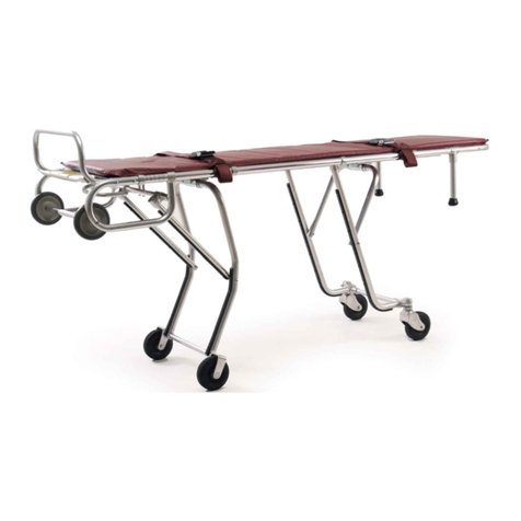
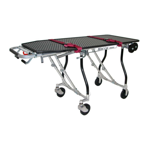
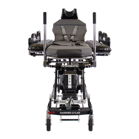
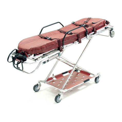
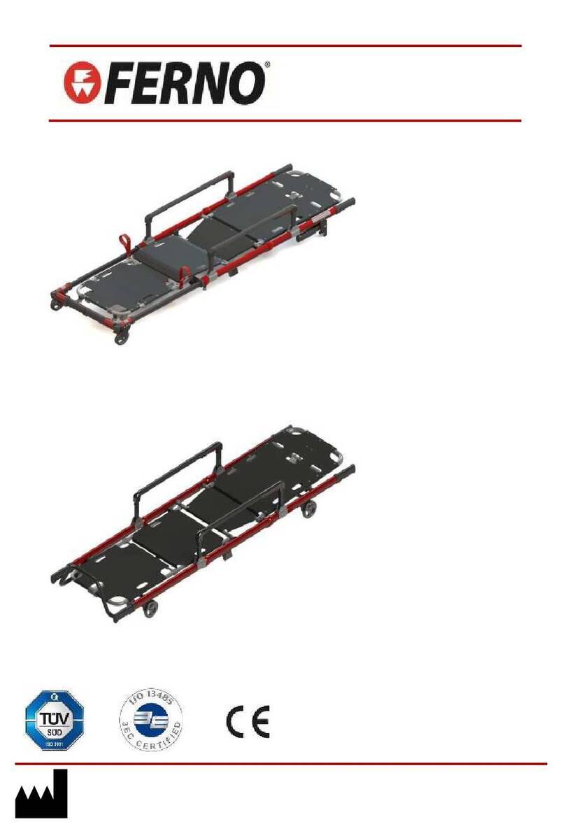
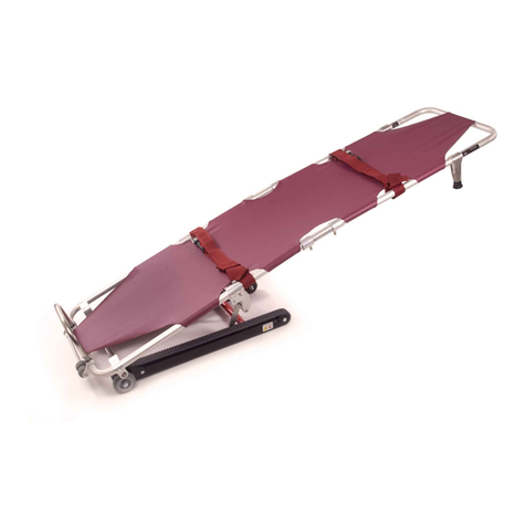
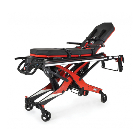
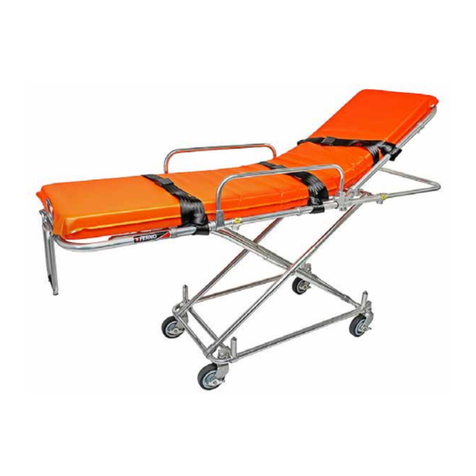
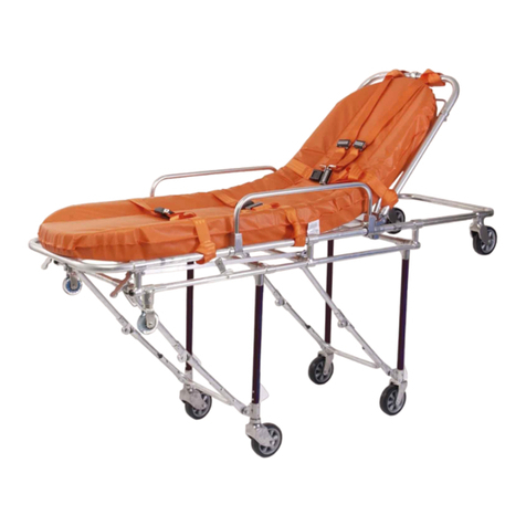
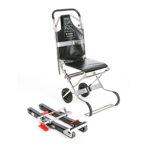
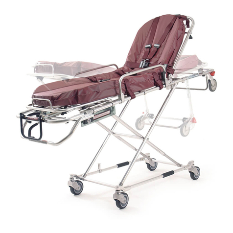
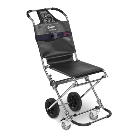
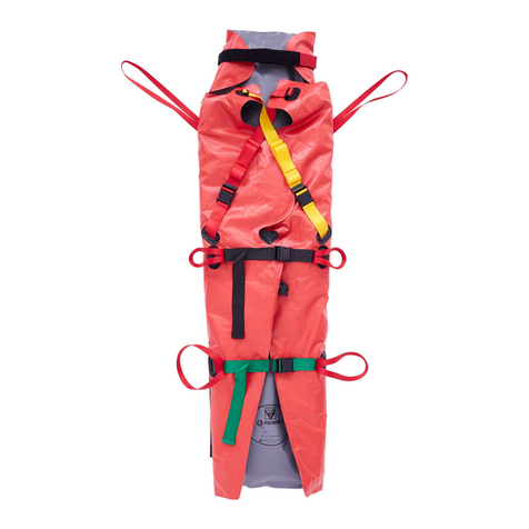
Ferno 26-S User manual

User and
Maintenance Manual
26-S Self-loading Stretcher
Rel. 241115
English
Read this manual
carefully and keep it
for future reference.

2© Ferno Washington Italia 26-S - Rel. 241115 ENG
26-S Self-loading Stretcher
© Copyright Ferno Washington Italia s.r.l. All Rights Reserved.
USER AND MAINTENANCE MANUAL
To request additional free copies of the
instruction manual, please contact Ferno
Washington Italia's Customer Services.
Ferno Technical Support
Customer Service and Technical Support are important aspects of
every Ferno product. Before contacting us, note the serial number
of the product and specify it in all written communications. For all
queries concerning technical support, contact Ferno Washington
Italia s.r.l.:
Telephone (toll-free, Italy only) 800 501 711
Fax +39 0516861508
Email [email protected]
Ferno Customer Service
For assistance and further information, contact Ferno Washington
Italia s.r.l.'s Customer Services:
MANUFACTURER
Ferno Washington Italia s.r.l., Via Benedetto Zallone 26
40066 - Pieve di Cento (BO) - ITALIA
Telephone (toll-free in Italy) 800 501 711
Phone +39 0516860028
Fax +39 0516861508
Website www.ferno.it
Limitation of Liability
This manual contains general instructions on the use and
maintenance of the product. The instructions do not cover all
possible applications and operations. The user is solely responsible
for proper and safe use of the product. The safety information is
provided as a service to the user and ensures only the minimum
required level of safety to prevent injury to operators and patients.
Any other safety measure implemented by the user must comply
with applicable regulations. Before using the product, it is strongly
recommended that staff be trained in its correct usage. Retain
this manual for future reference. In case of change of ownership,
ensure that the manual remains with the product. Additional free
copies can be obtained from Ferno Washington Italia's Customer
Services.
Intellectual Property Declaration
The information in this manual is the property of Ferno Washington
Italia s.r.l. of Via Benedetto Zallone 26, 40066 Pieve di Cento
(BO), Italy.
All patent rights, design rights, construction, reproduction, use and
sale relating to any item covered in this manual are the condential
and exclusive property of Ferno Washington Italia s.r.l., except for
rights expressly transferred to third parties or not attributable to
parties owned by the supplier. It is prohibited to reproduce this
manual, either in full or in part, without the prior consent of Ferno
Washington Italia s.r.l..
Limited Warranty
The products sold by Ferno are covered by a 24-month warranty
against manufacturing defects. For the full terms and conditions of
warranty and liability, see the Warranty chapter.
Compliance with safety regulations
The self-loading stretcher is designed and manufactured
by Ferno Washington Italia S.r.l. in complaince with the
safety requirements laid down by Directive 93/42/EEC
dated 14/06/93 (class I) regarding medical devices. All the
materials used are sized in order to operate properly within
the load limits given in the technical specications, and are
resistant to ame, produce no toxic or polluting substances,
and are protected to ensure a high resistance to wear and
corrosion. The design of the stretcher eliminated sharp edges
that may cause accidental injury to the personnel using it.
WARNING
Photos identied by "**" are for illustrative purposes
only. Please read the instructions carefully. The picture
does not represent the product described in this instruction
manual, but only correct usage and functionality.

3
© Ferno Washington Italia 26-S - Rel. 241115 ENG
26-S Self-loading Stretcher
Loading capacity
Respect the loading capacity of the 26-S stretcher. Refer to
General Technical Specications.
SAFETY INFORMATION
Read the user manual carefully. It is an integral part of the
product and must always be kept to hand. For your own
personal safety and that of your patients, please note the
following:
– Prior to each use, perform an inspection ensuring that
there are no signs of wear, damage, or malfunction. Refer to
the Inspection section.
– To prevent infection and / or bacterial contamination, refer
to the information in the Disinfection and Cleaning sections.
Warning
The danger symbols draw attention to potentially dangerous
situations that, if ignored, may result in accidents, damage
and/or injury.
WARNING
Untrained users may injure themselves, cause damage and/or
physical harm. Allow only trained and qualied to use the 26-S
stretcher.
The stretcher must be used by at least two trained and qualied
operators. The stretcher is for professional use.
Improper use of the stretcher can cause damage and / or injury. Use
the stretcher as described in this manual.
Unauthorised modication of the stretcher may cause serious
damage, injury and/or unforeseeable operational problems. Do not
modify or alter the stretcher in any way.
Any damage to the components of the stretcher or the entire system
can alter its performance and safety. Inspect the stretcher frequently,
and especially before and after each use. Place the stretcher out of
service if it shows signs of wear or damage.
An unassisted patient is at risk of injury. Never leave the patient
alone while bound to the stretcher. Always assist the patient
throughout all rescue operations.
A patient is not secured by the restraint system may fall and be
injured. Use the restraints to secure the patient to the stretcher.
Failure to use the restraints can cause the patient to fall and endanger
their safety. Always use the restraints to secure the patient.
Casual assistants may cause damage and/or physical harm, or
injure themselves. Do not allow casual helpers to perform stretcher
preparation operations. Trained operators should be alert and direct
operations involving the stretcher.
Improper maintenance may cause serious accidents, injuries and/
or damage. Perform maintenance as instructed in this user manual.
The use of improper or unauthorised devices may cause accidents,
damage and/or injury. Use only devices that have been approved
and authorised by Ferno Washington Italia.
Important
Boxes labelled "Important" contain important
information on use and/or maintenance of the device.
Important
Blood-borne diseases
To reduce the risk of exposure to infectious diseases that
may be transmitted by blood, such as HIV-1 or Hepatitis,
carefully follow the instructions on disinfection and cleaning
in this manual.
WARNING
Unauthorised repairs, and repairs carried out by people not
approved by Ferno Washington Italia, will render all warranties
null and void and may compromise the safety of the device.
Non-original spare parts and inadequate repairs may cause
damage and/or injury. Use only Ferno original parts and contact
only Ferno Washington Italia's Customer Support.
Compatibility with locking systems
The 26-S stretcher is compatible with the Ferno SLAM
locking system for ambulance transport. Ferno recommends
using only Ferno clamping systems with Ferno stretchers,
and to use Ferno locking systems only with Ferno stretchers.
It is recommended to use compatible Ferno locking systems
with the stretcher 26-S.
Any other conguration is not compatible with the
specications and instructions in this manual. Any
combination of a stretcher or a Ferno locking system with
a stretcher or a locking system not produced by Ferno is an
improper use of the Ferno product. Ferno Washington Italia
is not liable for damages caused to users or third parties
arising from improper use of the 26-S stretcher.
4© Ferno Washington Italia 26-S - Rel. 241115 ENG
26-S Self-loading Stretcher
Glossary of Symbols
The symbols used in this manual and / or on the stretcher's labels are dened below. The CE mark is present on the stretcher
and in this manual.
Read the user manual
carefully
Do not wash with high
pressure water
Danger: Risk of
injury
Crush point
Keep your hands clear
The stretcher requires at least
two qualied operators for
correct use
2
This product meets
European Union
Standards
Do not lubricate. Lubricate
Unlocked Locked
Warning and safety labels
The information and safety labels contain important information that the user needs to know.
Read and follow label instructions. Replace worn or damaged labels immediately. To obtain replacement labels, contact Ferno
Washington Italia Customer Services. The labels shown below are attached to the stretcher.
During the unloading stage of the stretcher, the operator at
the foot end of the patient (and any helpers) must support the
weight of the stretcher, the patient and the equipment used,
in order to allow the legs of the stretcher to open completely
and lock themselves into position.
Lifting the stretcher may require more effort for operators
of smaller stature, as such operators must raise their arms
higher relative to their shoulders.
Notes on the height and strength of operators
If the ambulance is located on an uneven surface, the
operator / operators at the foot of the patient may need to lift
the stretcher higher than usual to ensure that the legs open
and lock correctly during the unloading stage.
Note: Request additional help to lift the weight of the
stretcher, the patient and the equipment used (See the
Additional Help section.)
Load capacity (in kilos and
pounds)
MAX
181 kg
400 lb
SWR
Never exceed the load capacity of the
26-S stretcher. Inspect the stretcher if the
carrying capacity has been exceeded (see
Inspection section).
SWR- Strength to Weight Ratio = 5.5
Safety factor = 1.5

5
© Ferno Washington Italia 26-S - Rel. 241115 ENG
26-S Self-loading Stretcher
OPERATOR TRAINING AND SKILLS
WARNING
Untrained users may injure themselves, cause
damage and/or physical harm. Allow only trained
and qualied sta to use the 26-S stretcher .
Important
Operators must be able to ensure the safety of both themselves
and their patients while using the stretcher. They must be able
to assess the number of people needed to move the patient
according to applicable regulations.
Skills
Operators who use the stretcher must:
● have specic experience in patient immobilization,
handling, and recovery procedures.
● possess the appropriate skills to assist the patient.
Training
Operators are required to:
● read and understand all information in this manual.
● attend a suitable training course on the use of the
stretcher.
● practice with the stretcher before using it in real
situations with patients.
● log the training sessions. Example of a form for
logging training sessions.
Related Products and Accessories
Codes are subject to change; conrm them during the purchase
Self-loading stretcher (PR-26)
LBS (Large Body Surface) (0819991)
LBS Mattress (Foldable) (06-031-4025C)
ITI (Incubator Transporter Interface) (ITI)
IV pole (513-10E)
Pac-Rac (0818933)
4-Point Restraints (0313915)
1-piece restraints (430-1-N)
2-Piece restraints (430-2-N)
Mattress (0374857)
SLAM Lock (SLAM-26)
ITI
Mattress and LBS
IV Pole Pack Rack
Material transporter
SLAM locking mechanism
KT BLACK-26 Mattress

6© Ferno Washington Italia 26-S - Rel. 241115 ENG
26-S Self-loading Stretcher
THE STRETCHER
Description
The 26-S stretcher (known simply as the "stretcher" in this
document) is a device for handling patients in emergency
situations and is designed for transporting the patient in an
ambulance. It allows you to carry a patient securely thanks
to the system of safety restraings (for the restraints, see the
Accessories chapter.)
The stretcher should be used only by trained and qualied
staff. The stretcher is for professional use by at least two
qualied operators. It was designed to reduce the risk of
back injuries to healthcare workers. Additional assistance
may be required to handle heavy patients and/or when
the situation demands it, and should always be provided
according to local health protocols.
The stretcher has been designed to be used exclusively with
Ferno ambulance locking systems (for available locking
systems, see Accessories.)
WARNING
Improper use of the stretcher can cause damage
and / or injury. Use the 26-S stretcher as described
in this manual.
STRETCHER COMPONENTS
● Head-end carrying handle
● Control handles on rear legs
● Loading wheels
● Backrest adjustment lever
● Adjustable back
● Front legs
● Rear legs
● Front wheels, diameter 100 mm)
● Collapsible side rails
● Control for mechanical release of rear legs
● Rear wheels, diameter 100 mm with integrated brake
system
● Shock-proof frame
● Mechanical rear leg release system
● Leg locking system
● Foot-end carrying handle
WARNING
Untrained users may injure themselves, cause
damage and/or physical harm. Allow only trained
and qualied sta to use the 26-S stretcher.
WARNING
The use of improper and/or unauthorised devices
can cause accidents, damage and/or injury. Use only
devices that have been approved and authorised by
Ferno Washington Italia.
CE Compliance
MEDICAL DEVICES DIRECTIVE
Ferno's products meet the requirements of European
Directive 93/42/EEC concerning medical
devices. The stretcher is a Class I device.
For more information: www.ferno.it

7
© Ferno Washington Italia 26-S - Rel. 241115 ENG
26-S Self-loading Stretcher
Components (Stretcher)
Head-end
carrying
handle
HEAD END
FOOT END Backrest
adjustment
handle
Adjustable backrest
Loading wheels
Front wheels
Rear wheels with
integrated brake
Collapsible side rails
Shockproof frame
Foot end
carrying handle
Leg locking system
Safety rod
Control levers
USER AND MAINTENANCE MANUAL
To request additional free copies of the
instruction manual, contact Ferno Washington
Italia Customer Service.
Load capacity (in kilos and
pounds)
MAX
181 kg
400 lb
SWR
Never exceed the load capacity of the
26-S stretcher. Inspect the stretcher if the
carrying capacity has been exceeded (see
Inspection section).
SWR- Strength to Weight Ratio = 5.5
Safety factor = 1.5

8© Ferno Washington Italia 26-S - Rel. 241115 ENG
26-S Self-loading Stretcher
General technical specications
Ferno reserves the right to change the specications without
notice. For more details, please contact Ferno's Customer
Service.
Specications
Loading capacity 400 lbs 181 kg
Weight** 73 lbs 33 kg
Patient Height
Maximum Setting 31 in 800 mm
Minimum Setting 17 in 450 mm
Length
Maximum 77.56 in 1920 mm
Minimum 77 in 1957 mm
Width
Total 21.65 in 550 mm
Wheels
Diameter 3 in 100 mm
Width 1.6 in 40 mm
Materials
Structure aluminium
Panels ABS
Wheel bearings sealed
Loading height*
Loading level 24/25 in 610/640 mm
Stretcher positions
**Transport position
**Completely closed
* The loading height is the distance between the ground and
the lower part of the oor-level wheels.
** The weight of the stretcher does not include mattress and
restraints.
The load limit includes the weight of the stretcher, the
patient, the equipment and, in some situations, and the
rescuer. Exceeding this limit may result in harm to the
patient and / or the stretcher.
The dimensions are rounded to integers. As a result of
product improvements, these specications are subject to
change without notice.
For all other questions, contact customer service (see the
"Customer Service" section).
Technical specications
The stretcher is equipped with:
• Leg-locking bar
• Leg-actuating levers
• Safety rod
• Collapsible side rails
• Adjustable backrest
• Foldable frame
• Anti-shock frame
- Wheel brakes
WARNING
Photos identied by "**" are for illustrative purposes
only. Please read the instructions carefully. The picture
does not represent the product described in this instruction
manual, but only correct usage and functionality.

9
© Ferno Washington Italia 26-S - Rel. 241115 ENG
26-S Self-loading Stretcher
Control levers
The two control levers are positioned at the foot end of
the stretcher. These operate the mechanism that closes and
opens the legs.
From the rescuer's perspective at the feet of the patient, the
right-hand lever controls the head-end legs of the stretcher,
while the one to the left controls those at the patient's feet.
These levers can be operated only after the safety rod on the
right side, and below the patient level, of the stretcher has
been unlocked.
To change the height of the stretcher, both operators must
hold the frame of the stretcher with palms facing up. The
operator at the foot end disengages the safety rod and
operates both levers at the same time, while pro-actively
warning the second operator (see g. 5).
When loading or unloading the stretcher from the ambulance,
the operators use one lever at a time, making sure to use the
stretcher as described in this instruction manual
Safety rod
The safety rod is placed under the patient, on the operator's
right side.
When locked, the safety rod prevents accidental closure of
the legs due to accidental movement of the levers.
The safety rod is locked automatically when the stretcher
changes from the "closed" to the "open" position. Keep
the safety rod locked in place during all phases that do not
specically require its release (e.g. any movement of the
stretcher).
To disengage the safety rod, pull the end towards you when
at the foot end of the stretcher.
Carrying handle
The stretcher is equipped with a carrying handle at the foot
end (Figure 4.) The operator at the foot end of the stretcher
uses the carrying handle to guide and move the stretcher.
The patient should be able to see where they are going
and the castor wheels should be rotated to face the same
direction.
Figure 4 - Carrying handle (foot end)
STRETCHER COMPONENTS

10 © Ferno Washington Italia 26-S - Rel. 241115 ENG
26-S Self-loading Stretcher
Folding front frame
Use the collapsible frame to reduce the length of the stretcher
when operating in conned spaces, such as in elevators or
narrow corridors.
1. Raise the backrest.
2. Support the front part of the frame and operate the locking
lever by pulling it toward the front of the stretcher.
3. Lower the folding portion of the frame gently, while
keeping it from falling freely. The chassis can be lowered to
two positions: an intermediate position, and a fully lowered
position. (Figure 7A)
7A
Wheels
The stretcher is equipped with four large, swivelling wheels,
(diameter 100 mm), two front and two rear, that are self-
directing to facilitate loading into the vehicle. (Figure 7B).
The two rear swivel wheels are each equipped with an
integrated brake system (see the System integrated brake
section.) The design protects the wheels from dirt and liquid
ingress.
Integrated brake system
The brake prevents accidental movement of the stretcher
(Figure 12), while transferring the patient, when the stretcher
is not on a at surface, or during certain medical procedures.
The brakes are tted the rear wheels of the stretcher and
easily identiable by the operator thanks to the red locking
lever.
Use the wheel brakes to keep stretcher from moving when
it is on an uneven surface, while transferring patients on
stretchers, or supports at the same height as the stretcher,
and during medical procedures on the patient.
Lock the stretcher when it is in a parking position (stopped);
do not use the wheel locks as brakes while moving the
stretcher.
To lock or unlock the rear wheels, proceed as follows:
● TO LOCK THE WHEELS: Press down with your
foot on the red levers on the rear wheels (Figure 13.)
● TO RELEASE THE WHEELS: Lift the red locking
levers off the rear wheels with your foot.
Figure 7B: Brake system
Integrated brake

11
© Ferno Washington Italia 26-S - Rel. 241115 ENG
26-S Self-loading Stretcher
Backrest
The stretcher is tted with a backrest that can be adjusted up
to 80° (Figure 7C). The operator can adjust the backrest by
raising or lowering the appropriate red release lever.
Before adjusting the backrest:
○Loosen the restraints
○Support the backrest while operating the lever.
● TO RAISE THE BACKREST: Push the lever
(towards the stretcher body) to release the backrest,
then lift it to the desired position. Release the lever and
lift the backrest slightly to lock it into position.
● TO LOWER THE BACKREST: Press the lever
(towards the stretcher body) to release the backrest,
then lower it to the desired position. Release the lever
and lift the backrest slightly to lock it into position.
● Readjust the restraints.
7C
Figure 7 - A: Backrest
B: unlocking lever action
Important
Do not use the side rails to lift the stretcher (Figure
9A.) The sides rails are not suitable for lifting the
stretcher. Lift the stretcher holding the main frame
(Figure 9B.)
Side Rails
The stretcher is tted with collapsible side rails on both
sides (Figure 8A.) The operator can raise or lower the side
rails using the release pins.
● TO LOWER THE SIDE RAILS: Pull the release pin
knob (Figure 8B) and rotate the side rails downwards.
Release the knob to lock the rails in place.
● TO RAISE THE SIDE RAILS: Pull the release pin
knob (Figure 8B) and rotate the side rails upwards.
Release the knob to lock the rails in place.
Figure 8 - A: Collapsible side rails
B: Release pin for raising or lowering the side rails
8B
8A
Side rail release pin

12 © Ferno Washington Italia 26-S - Rel. 241115 ENG
26-S Self-loading Stretcher
Figure 9 - A: INCORRECT lifting of the stretcher
B: CORRECT lifting of the stretcher, holding the main frame
9A 9B
CORRECT
LIFTING OF THE
STRETCHER
Anti-shock Frame
The stretcher has an anti-shock frame (Figure 10A.) The
frame allows you to place the patient in the Trendelenburg
position (legs raised).
Before lifting / lowering the frame:
Grasp the frame and maintain your grip while lifting or
lowering the frame.
Raise or lower the frame while always standing at the foot
end, at the side.
TO LIFT THE FRAME
1) Detach or loosen the restraints holding the legs and
waist of the patient. Raise the frame to the desired position
(Figure 10B), locking it in place. 2) Re-attach and adjust the
restraints over the legs and waist of the patient.
TO LOWER THE FRAME:
1) Detach or loosen the restraints holding the legs and
waist of the patient. Unlock the support bars by lifting and
lowering the frame to the desired position, then locking it
into place. Re-attach and adjust the restraints over the legs
and waist of the patient.
2) Stay with the frame until it reaches the nal position.
3) Adjust the restraints.
**Figure 10 - A: Anti-shock frame
B: Raise the anti-shock frame
10A
10B

13
© Ferno Washington Italia 26-S - Rel. 241115 ENG
26-S Self-loading Stretcher
Leg-locking system
The leg-locking bar is a device that ensures the legs remain
in the folded position. This allows trained operators to lock
the legs and carry the stretcher in "sedan chair" style over
rough terrain or paths with obstacles. Warning: Back injury
may occur (Figure 14A)
To operate the leg-locking bar:
1. Place the stretcher in the loading position on the ground,
ensuring the mechanisms are aligned.
2. Pull the bar handle (g. 14B).
3. Check for correct locking.
To operate the leg-locking bar:
Push the bar handle to the bottom to ensure that, while
loading patient, the bar is not bent and therefore no longer
functional. 14A
14B
WARNING
Do not operate the leg-locking bar when the stretcher
is loaded into the ambulance. Verify that the leg-
locking bar is disengaged before unloading the
stretcher from the ambulance
WARNING
Use of the stretcher in sedan mode may jeopardize
safety; always evaluate the use of assistance
Important
Stretcher leg-locking bars with serial numbers
below L.666059 Operate in the reverse direction to
that described in this manual. Use the relevant previous
version of the manual, or upgrade the stretcher to the
current version: info@ferno.it

14 © Ferno Washington Italia 26-S - Rel. 241115 ENG
26-S Self-loading Stretcher
Before commissioning the stretcher
Staff using the stretcher must have carefully read and
understood the information contained in this manual. Before
any operation with the stretcher ensure that:
● all components, restraints, and mattress are present.
● That the stretcher shows no signs of damage and
wear, and is fully operational. Refer to the Inspection
section.
● The vehicle is tted with a Ferno locking system
compatible with the 26-S stretcher.
Instructions for Use
● This manual does not provide any medical instructions.
● It is the responsibility of the operators to follow correct
procedures and ensure the safety of both the patient
and themselves.
● This manual explains the use of the stretcher under
ideal conditions and is purely indicative.
● The stretcher should be used only by trained and
qualied staff.
● Operators must work together and coordinate
properly during all operations.
● Follow procedures while complying with standard
protocols for handling the patient in an emergency.
● Lift only the weight that you can safely support. Obtain
additional help when working with heavy loads.
● Always observe the instructions and local health
protocols.
● Always assist the patient and never leave the patient
alone during operations involving the stretcher.
● When changing the height (position) of the stretcher,
or while unloading it from the ambulance, make sure
the legs are locked before letting go of the main frame.
WARNING
Improper use of the stretcher can cause damage
and / or injury. Use the 26-S stretcher as described
in this manual.
WARNING
Never leave the patient alone while bound to
the stretcher. Always assist the patient during all
operations on a stretcher by two operators.
USING THE STRETCHER
Read the user manual
carefully
Loading capacity
MAX
181 kg
400 lb
2
Use with a minimum of two
qualied operators
WARNING
The use of improper or unauthorised devices may
cause accidents, damage and/or injury. Use only
devices that have been approved and authorised by
Ferno Washington Italia.
Important
For heavy loads, the two operators, after placing the
loading wheels on the oor and pushing the stretcher
onto the loading area securely, can move to the foot
end and push simultaneously. The same applies
to unloading: after having ensured the rear leg is
supporting, an operator returns to the central position
and controls the full movement of the front leg.
WARNING
Photos identied by "**" are for illustrative purposes
only. Please read the instructions carefully. The picture
does not represent the product described in this instruction
manual, but only correct usage and functionality.

15
© Ferno Washington Italia 26-S - Rel. 241115 ENG
26-S Self-loading Stretcher
Lifting and lowering
Two trained and qualied operators are required for lifting
and lowering of the stretcher.
• LIFTING THE TROLLEY
1. The operators should make sure they support the
weight of the stretcher and the patient while raising
and lowering the stretcher.
2. Head-end operator: move to the foot end of the
stretcher. This ensures control of the stretcher; lift by
grasping the central tube with palms facing upward.
3. Foot-end operator: move to the head of the stretcher.
This ensures control of the stretcher; lift by grasping
the central tube with palms facing upward, without
using the control lever.
4. Both operators: The safety is triggered automatically
after the legs complete their movement. Always hold
the stretcher once the loading level is reached, and
lower the stretcher to the ground after ascertaining that
the mechanisms are locked into place.
5. Both operators: Coordinate with each other to lift the
stretcher to the desired height.
6. Both operators: Make sure you have successfully
locked the stretcher at the desired height.
• TO LOWER THE TROLLEY
1. Lift the folding front frame, bringing it to the horizontal
position and the same to the folded position.
2. Both operators: Positioned at the head and foot of the
stretcher, ensuring total control of the stretcher.
Grasp the central tube with palms facing upwards and
operate the control handles while supporting the
weight.
Push the control handles and lower the stretcher with
coordinated movements to the desired height.
While keeping control of the stretcher, release your grip on
the handles, making sure you have successfully locked
the stretcher at the desired height.
**Figure 15 - Position of the operators for lifting and
lowering the stretcher
Important
Always make sure the stretcher is correctly locked to
the desired height when raising or lowering it, and
before loosening your grip on the frame.
LOWERING TO THE GROUND BY ONE OPERATOR
When the transport system is empty (not occupied by a
patient), an operator can lower the stretcher to ground level
on their own.
1. Fasten all the restraints in order to keep them touching
the ground and getting trapped underneath.
2. Tilt the stretcher onto the front loading wheels
3. Disengage the safety rod
4. Grasp the stretcher securely and press the right lever to
unlock the front legs
5. Lower the stretcher until the rear legs support its
weight
6. Press the left-hand lever and lower the stretcher gently
the to the ground
ONE OPERATOR FOR LOADING AND UNLOADING
If local protocols so provide, the empty transport system can
be loaded and unloaded from the ambulance by a qualied
operator. Follow the procedures in the How to load the stretcher
and How to unload the stretcher sections.
WARNING
Failure to use the restraints can cause the patient
to fall and endanger their safety. Always use safety
restraints for the patient made by FernoWashington
Italia.

16 © Ferno Washington Italia 26-S - Rel. 241115 ENG
26-S Self-loading Stretcher
Loading and unloading
Before proceeding with the loading or unloading of the
stretcher, the two operators must always be prepared to
support the weight of the stretcher and patient, and also for
the possibility of a "back off" phase, and any other connected
equipment. Make sure you have applied the restraints and
that the patient is correctly secured.
To load or unload the stretcher, proceed as follows:
• TO LOAD THE STRETCHER
Lift the front frame, folding it back into the horizontal
position and that it is in the "folded" position. Carry the
stretcher to the loading door of the ambulance, ensuring it is
perpendicular to the entrance; this manoeuvre must always
be performed by two operators guiding the stretcher.
1. Head-end operator: Assists the foot-end operator,
holding the central tube with palms facing up while aligning
with the loading bay. (Figure 16).
2. Head-end operator: After verbal contact with his
colleague, push the stretcher onto the loading level after
ascertaining that the loading wheels are supported beyond
the initial ramp.
3. Foot-end operator: Operate the safety lever, located
below the patient level, to the right.
4. Foot-end operator: Press the right-hand lever to lock the
front legs (head end). Pushing the weight of the stretcher
into the ambulance until the rear legs come into contact
with the back of the vehicle. (We recommend both operators
working simultaneously to reduce the possibility of spinal
damage).
5. Both operators: Position at the foot end and proceed
together with the loading of the stretcher (Figure 17),
pushing it up to complete the loading of the stretcher into
the ambulance.
6. After loading the stretcher, be sure to lock the stretcher
inside the ambulance using the SLAM locking system.
• UNLOADING THE STRETCHER
1. Release the SLAM stretcher locking system
2. Head end operator: Stand beside the stretcher to the
side, palms facing upwards on the central tube, and assist
the foot-end operator.
3. Foot end operator: With both hands, grasp the frame
with palms facing upward, and start pulling the stretcher out
of the ambulance. Ensure the rear legs open fully and are
resting against the ground. (We recommend unloading one
at a time to reduce possibility of spinal damage).
** Figure 16 - Position of the operators for the loading
the stretcher
** Figure 17 -Loading and / or unloading
the stretcher
** Figure 18 - Loading and / or unloading
the stretcher
Head EndFoot End

17
© Ferno Washington Italia 26-S - Rel. 241115 ENG
26-S Self-loading Stretcher
WARNING
Failure to use the restraints can cause the patient
to fall and endanger their safety. Always use the
safety restraints.
WARNING
An unassisted patient is at risk of injury. Never
leave the patient alone while they are bound to the
stretcher. Always be attentive to the patient during
all operations with the stretcher.
4. Head end operator: check that the front legs have
sufcient space to open fully.
5. Each time you unload the stretcher ensure both pairs of
legs are fully opened and locked before the wheels leave the
loading bay of the ambulance.
6. When both legs are open and locked in the normal
transport position, pull the stretcher completely out of the
ambulance.
7. Foot end operator: Complete the unloading operation
while coordinating with the operator at the head end and
keeping all four hands on the stretcher.
Important
During all transport, loading and unloading
operations, when handling heavy patients
(minimum 90 kg) additional operators are
recommended. This reduces the load on each
operator. For additional help, refer to the Additional
help section.
Transfer
Follow these steps to transfer the patient onto the stretcher:
1. Place the stretcher next to the patient, and adjust its
height – (to raise or lower the stretcher, see the Raising and
Lowering section ) – so that it is positioned level with the
patient.
2. Lock the rear wheels by pressing down brake lever with
the foot. (To lock the rear wheels, see Integrated brake
system.)
Transport
Before any transport make sure that: the restraints have been
applied to the patient, the side rails are raised and locked,
and the patient is secured correctly to the stretcher.
Carry the stretcher carefully over uneven surfaces.
If obstacles are encountered, such as the threshold of a door,
slightly lift, pull or push the stretcher so that the wheels
overcome the obstacle.
Avoid high obstacles, such as stairs. If there is a need to
overcome a high obstacle, or in case of difculty, lift and
carry the stretcher by resorting to the Additional help section.
Proceed as follows for the transport of the stretcher:
1. Fasten the restraints and adjust them so they do not
create discomfort to the patient.
3. Lower the side rails of the stretcher. (To raise and lower
the side rails, see the Rails section.)
4. Release the restraints.
5. Transfer the patient onto the stretcher following approved
medical procedures.
6. Fasten the restraints to secure the patient and adjust them
without constricting the patient.
7. Raise the side rails of the stretcher. (To raise and lower the
side rails, see Rails
Important
The two operators can stand at either side and lift the
stretcher step by step, thus sharing the total weight
and eort, and will not suer collateral harm. Bring it
up to the loading level. (Use additional helpers when
possible)

18 © Ferno Washington Italia 26-S - Rel. 241115 ENG
26-S Self-loading Stretcher
WARNING
Carry the stretcher so that the patient can see where it
is going. Ensure the castors are in the correct position
to improve security and overcome obstacles.
WARNING
For unusual transport or on difcult terrain, the
stretcher can be transported even at one or two lower
height levels, so as to increase its stability.
2. Make sure the side rails are raised and locked in
position.
3. Unlock the brake release lever on the rear wheels.
4. Foot end operator: grasp the frame of the stretcher, or
the carrying handle, and proceed with patient transport.
5. Head end operator: assist the foot end operator,
helping maintain control of the stretcher and checking
its path.
Additional assistance
Use of the stretcher requires at least two qualied operators.
The operators may need help for a heavy lift (patient and
equipment).
● operators must position themselves at the head and
foot of the stretcher, maintain control, and manage all
additional helpers.
● It may occasionally be required for the helpers at the
sides of the stretcher to walk sideways. Follow the
local healthcare protocols.
The illustrations below show the positioning of operators
and helpers.
Helpers Change position Transport Loading/unloading
Two
Operators
+
two
helpers
Two
Operators
+
four
helpers
Legend: O = operator, H = Helper, P = Patient

19
© Ferno Washington Italia 26-S - Rel. 241115 ENG
26-S Self-loading Stretcher
WARNING
Use only restraints from Ferno Washington Italia
Figure 1
Figure 4 Figure 3
Applying the restraints to the
stretcher
The use of the stretcher requires the use of special restraints
that are not supplied with the stretcher.
Ferno recommends using the stretcher with three restraints:
a four-point restraint for the chest and two restraints for the
femurs and feet. (See gures on the previous pages.
Keep the restraints fastened when not in use to prevent them
from interfering with the operations of the stretcher.
The following summarizes the methods of use of the
restraints.
Check that the restraints are intact and without undamaged.
All restraints listed work well with all Ferno stretchers.
Mount the 4-point restraint (0313915):
1. Raise the backrest of the stretcher and pass the belt below
the supporting bar placed in proximity of the ABS plastic
slot designed for the purpose on the surface. (Fig. 1.
2. Pass them through the mattress via the pre-spaced eyelets
(if the mattress lacks the eyelets, it must be replaced for the
correct operation of seat belts. (g. 2.
Installing the 2-piece restraints (430-1-N):
1. Unfasten the restraint and split it into two parts
The "femoral" restraint must be positioned exactly under the
rail, such that there is 40 cm of extrusion to allow it to be
precisely positioned on different types of patients. Wrap the
extremities in a shaped loop around the anchor point chosen,
always on the central tube of the stretcher (g. 3.
2. The foot belt must be positioned exactly with the rst,
near the last fusion of the frame placed next to the control
levers and the transport handle. (g. 4.
Figure 2
Loop knot
RESTRAINTS CONFIGURATION
Important
Always place the "female" end
on the LEFT of the patient (the
operator side in the ambulance)
to adjust the restraint with
patient on board while
remaining safely seated.

20 © Ferno Washington Italia 26-S - Rel. 241115 ENG
26-S Self-loading Stretcher
USING THE RESTRAINTS
WARNING
It is extremely important to always check the connection
of the parts before using the stretcher for either practice
or real-life situations.
To attach the 4-point restraint to the patient (417):
1. Pass the shoulder restraint over the shoulders of the patient
and arrange them until there is no contact. The connections
should be centred on the sternum or abdomen.
2. Fasten the belt by passing the metal buckle to "L" joints
and insert it into the hook buckle until it locks into position
(g. 1).
3. Always ensure the buckle is fastened
To release the restraint:
1. Press the red release button located in the central part of
the buckle.
2. Pull the tab from the joints
To extend the restraint with the patient on board:
1. Grasp the controller and turn it until it is perpendicular
to the belt. Pull in the opposite direction to the anchor point
until the belt is of the desired length. (g. 2)
To shorten the restraint:
Hold the sewn ends and pull the belt through the bar until it
is the desired length. (g. 3)
Figure 1
Figure 2
Figure 3
Table of contents
Other Ferno Medical Equipment manuals

Ferno
Ferno 23 User manual

Ferno
Ferno Megasus User manual

Ferno
Ferno Kwik Klip 031-4002 User manual

Ferno
Ferno 24 MAXX User manual

Ferno
Ferno 50-E User manual

Ferno
Ferno POWER X SN-POW1001 User manual

Ferno
Ferno CHI User manual

Ferno
Ferno EZ Glide 59-T User manual

Ferno
Ferno POWERFlexx User manual

Ferno
Ferno CCT Six - M User manual

Ferno
Ferno PEZO2 User manual

Ferno
Ferno Ultra Care 4000 User manual

Ferno
Ferno ScoopEXL Operating instructions

Ferno
Ferno One Man 27-1 User manual

Ferno
Ferno 35X-NM PROFlexx User manual

Ferno
Ferno 082-1997 User manual

Ferno
Ferno Mini Cot User manual

Ferno
Ferno CCT Six-P User manual

Ferno
Ferno Viper Stretcher User manual

Ferno
Ferno 35A-NM User manual