Ferno Transcend Chair Series User manual

Users’ Manual
August 2021
Pub. No. 234-3801-00
Transcend™Chair Series
Carry Chair, Manual Tracks, and PowerTraxx®
Read this Manual and Retain
for Future Reference

© Ferno / 234-3801-00 / August 2021
2
USERS’ MANUALS
To request additional free users’ manuals,
contact Ferno Customer Relations, your Ferno
distributor, or www.ferno.com.
Disclaimer
This manual contains general instructions for the use, operation and
care of this chair. The instructions are not all-inclusive. Safe and proper
use of this chair is solely at the discretion of the user. Safety information
is included as a service to the user. All other safety measures taken
by the user should be within and under consideration of applicable
regulations and local protocol. Training on the proper use of this chair
must be provided before using this chair in an actual situation.
Retain this manual for future reference. Include it with the chair in the
event of transfer to new users. Additional free copies are available upon
request from Customer Relations.
Proprietary Notice
The information disclosed in this manual is the property of Ferno-
Washington, Inc., Wilmington, Ohio, USA. Ferno-Washington, Inc.
reserves all intellectual property rights, proprietary design rights,
manufacturing rights, rechairion use rights, and sales use rights thereto,
and to any article disclosed therein except to the extent those rights
are expressly granted to others or where not applicable to vendor
proprietary parts.
Limited Warranty Statement
The chairs sold by Ferno are covered by a limited warranty, which is
printed on all Ferno invoices. The complete terms and conditions of
the limited warranty, and the limitations of liability and disclaimers,
are also available upon request by calling Ferno at 1.800.733.3766 or
1.937.382.1451.
Adverse Event Notice
In the event of an adverse event or serious incident related to the use of this
device, the end user/operator must report the incident to Ferno-Washington,
Inc. at 70 Weil Way, Wilmington, Ohio 45177 USA, 1-877-733-0911, or via
Union, report it to Ferno’s Authorized EU Representative and the competent
authority of the Member State in which the end user is established.
Ferno Customer Relations
For ordering assistance or general information:
CANADA AND THE U.S.A.
Telephone (Toll-free) 1.877.733.0911
Telephone 1.937.382.1451
Fax (Toll-free) 1.888.388.1349
Fax 1.937.382.1191
Internet www.ferno.com
ALL OTHER LOCATIONS
For assistance or information, please contact your Ferno distributor. If
you do not have a Ferno distributor, please contact Ferno Customer
Relations:
Ferno-Washington, Inc., 70 Weil Way
Wilmington, Ohio 45177-9371, U.S.A.
Telephone Country Code +1.937.382.1451
Fax Country Code +1.937.382.6569
Internet www.ferno.com
Unique Device Identication (UDI)
Ferno complies with the United States Food and Drug Administration’s (FDA)
Unique Device Identication (UDI) regulation to identify medical devices.
The UDI label contains information in human- and machine-readable form.
Device information is online at the FDA’s Global Unique Device Identication
Database (GUDID). The public can search and download information at
AccessGUDID at www.fda.gov.
The label is located on the chair frame behind the back panel.
Ferno-Washington Inc. | Wilmington, Ohio 45177 USA | +1.937.382.1451
Product Name/Model
(01) Global Trade Item Number
(11) Date of Manufacture
(21) Serial Number
Date of Manufacture
SN Serial Number
Manufacturer GS1 Data Matrix

© Ferno / 234-3801-00 / August 2021 3
TABLE OF CONTENTS
Ferno Customer Relations ________________________________ 2
Unique Device Identication (UDI) _________________________ 2
1 - Safety Information _____________________________________ 4
1.1 Warning__________________________________________ 4
1.2 Notice ___________________________________________ 4
1.3 Tip ______________________________________________ 4
1.4 Bloodborne Disease Notice __________________________ 4
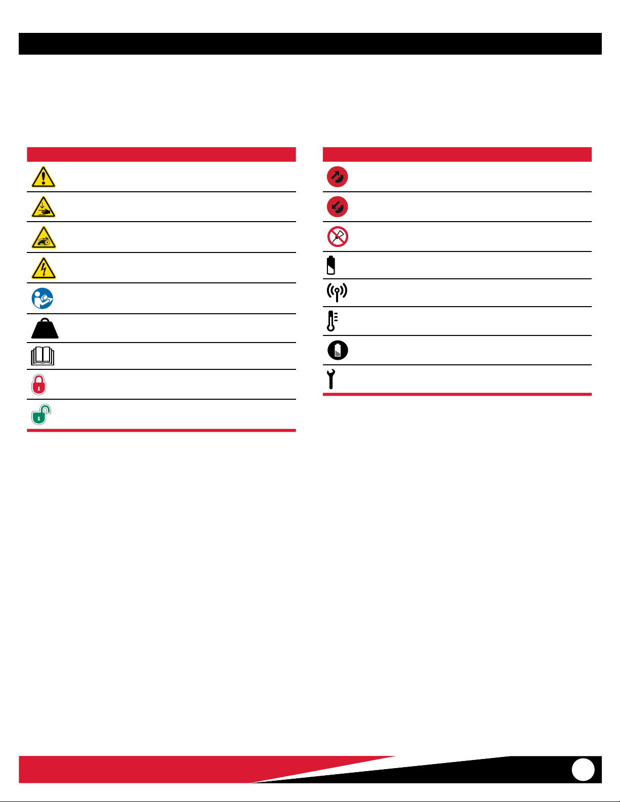
1.5 Symbol Glossary ___________________________________ 5
1.6 Safety and Instruction Labels _________________________ 6
1.7 Compliance _______________________________________ 6
2 - Operator Focus ________________________________________ 7
2.1 Operator Training __________________________________ 7
2.2 Daily Operator Duties _______________________________ 7
2.3 Using Additional Help_______________________________ 8
3 - About the Chair ________________________________________ 9
3.1 Description _______________________________________ 9
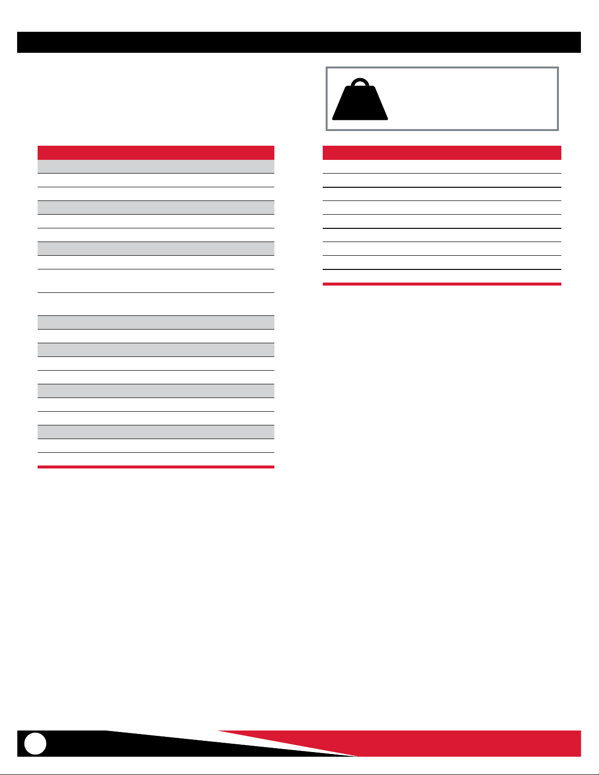
3.2 General Specications _____________________________ 10
3.3 Component: Carry Chair & Manual Track Chair __________ 11
3.4 Components: PowerTraxx___________________________ 12
4 - PowerTraxx System ____________________________________ 13
4.1 PowerTraxx Components ___________________________ 13
4.2 Main Battery _____________________________________ 14
4.3 Attaching and Removing the Main Battery _____________ 15
4.4 PowerTraxx Controller _____________________________ 15
4.5 Scene Lights _____________________________________ 16
4.6 Sleep Mode ______________________________________ 16
5 - Features and Options __________________________________ 17
5.1 Track System (Excludes Carry Chair)___________________ 17
5.2 Lift Bar __________________________________________ 18
5.3 IV Bag Clip _______________________________________ 18
5.4 Rear Lift Handles__________________________________ 19
5.5 Telescoping Lift Handles____________________________ 19
5.6 Armrests ________________________________________ 19
5.7 Footrest _________________________________________ 20
5.8 Wheel Locks _____________________________________ 20
6 - Using the Chair _______________________________________ 21
6.1 Before Placing the Chair in Service ___________________ 21
6.2 General Guidelines for Use__________________________ 21
6.3 Folding and Unfolding the Chair _____________________ 22
6.4 Transferring the Patient ____________________________ 23
6.5 Rolling the Chair __________________________________ 23
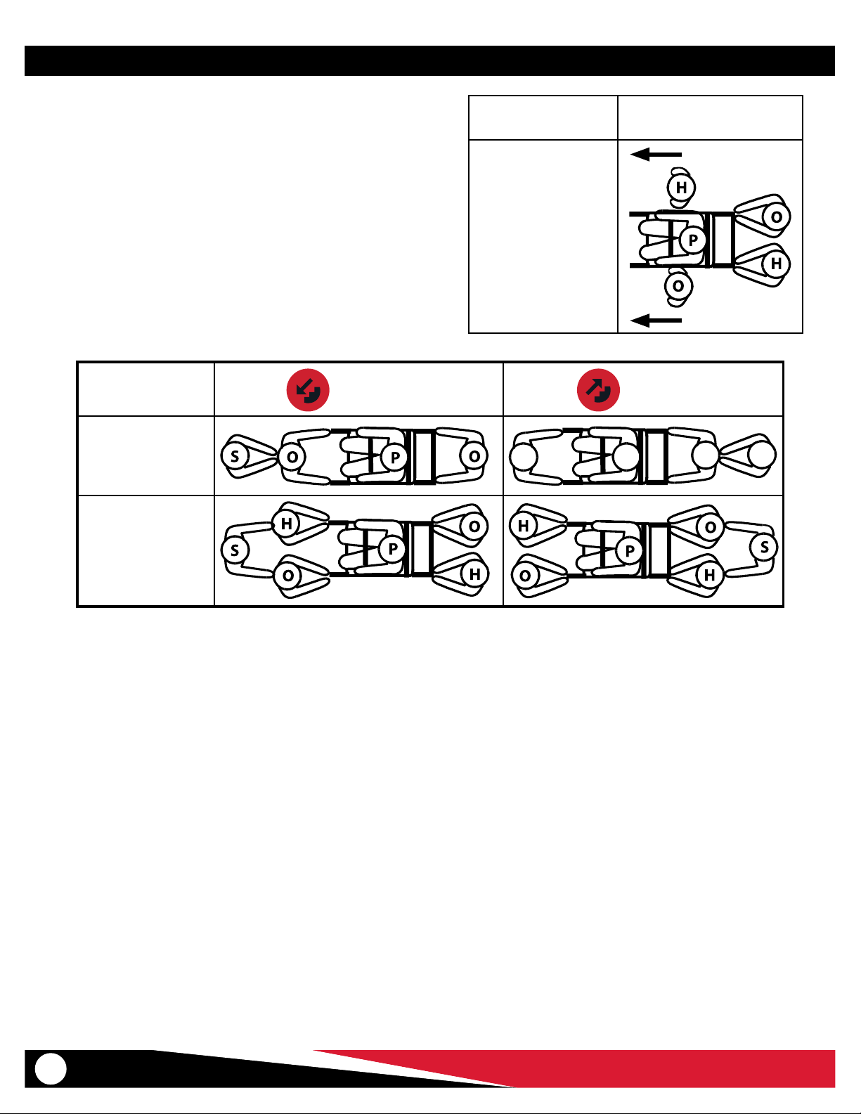
6.6 Transporting the Patient Down Stairs _________________ 24
6.7 Transporting the Patient Up Stairs____________________ 27
6.8 Pausing On the Stairs ______________________________ 29
6.9 Using a PowerTraxx Chair Without Power ______________ 29
7 - Maintenance _________________________________________ 30
7.1 Maintenance Schedule_____________________________ 30
7.2 Disinfecting/Cleaning Restraints _____________________ 30
7.3 Disinfecting/Cleaning the Chair______________________ 30
7.4 Cleaning Tracks and Belts ___________________________ 30
7.5 Lubrication-Free Chair and Tracks ____________________ 30
7.6 Inspecting the Chair _______________________________ 31
7.7 Controller Battery _________________________________ 32
7.8 PowerTraxx Motor Status Lights______________________ 32
7.9 Removing and Attaching the Backrest and Seat Panels ___ 33
7.10 Interconnect Cord for PowerTraxx ____________________ 34
7.11 Storing the Main Battery ___________________________ 35
7.12 Recycling Notice __________________________________ 35
8 - Initial Setup __________________________________________ 36
8.1 First-Time Setup __________________________________ 36
8.2 Ankle Restraint ___________________________________ 36
8.3 Attaching Patient Restraints_________________________ 37
8.4 Restraint Congurations____________________________ 37
9 - Parts and Service______________________________________ 38
9.1 U.S.A. and Canada_________________________________ 38
9.2 Worldwide_______________________________________ 38
9.3 Parts List ________________________________________ 38
10 - Accessories__________________________________________ 40
Training Record__________________________________________ 41
Maintenance Record _____________________________________ 42
Notes __________________________________________________ 43
Section Page Section Page

© Ferno / 234-3801-00 / August 2021
4
1 SAFETY INFORMATION
1.1 Warning
Warning safety alerts indicate a potentially hazardous situation that, if
not avoided, could result in injury or death.
1.4 Bloodborne Disease Notice
To reduce the risk of exposure to blood or other potentially infectious
materials when using the chair, follow the disinfecting and cleaning
instructions in this manual.
Safety Information
1.3 Tip
Tips provide recommendations for easier use of the chair.
1.2 Notice
Notices emphasize important, but not hazard-related information.
Failure to follow Notices could result in chair or property damage.
NOTICE
WARNING
DO NOT OPEN POWER UNIT.
No user-serviceable parts inside. Contact
Ferno for service.
WARNING
Untrained helpers can cause injury or be injured. Trained
operators must operate the controls and direct helpers
where to grasp the chair to avoid pinch points.
Improper use of the chair can cause injury. Use the chair
only for the purpose described in this manual.
Improper charging can cause injury or damage. Use only
the Ferno-approved battery with the chair, and charge
only with the Ferno-approved battery charger.
Modifying the battery can cause injury and damage. Use
the battery only as designed by Ferno.
Improper maintenance can cause injury and damage.
Maintain the chair and battery only as described in this
manual.
Using the chair with an unlocked track system can cause
injury. Verify that the track system is locked before
transporting the patient.
Lubricating the track system can result in injury to the
patient and/or operators. Never lubricate the tracks or
belts.
Improper operation can cause injury. Operate the chair
only as described in this manual.
An unattended patient can be injured. Stay with the
patient at all times.
An unrestrained patient can be injured. Use patient
restraints to secure the patient on the chair.
Track Chair Models: Using the chair with the track system
unlocked can cause injury. Verify that the track system is
locked before transporting the patient.
Improper maintenance can cause injury. Maintain the
chair only as described in this manual.
Attaching improper items to the chair can cause injury.
Use only Ferno-approved items on the chair.
Improper parts and service can cause injury. Use only
Ferno parts and Ferno-approved service on the chair.
Modifying the chair can cause injury and damage. Use the
chair only as designed by Ferno.

© Ferno / 234-3801-00 / August 2021 5
Safety Information
1.5 Symbol Glossary
The symbols dened here are used on the chair and/or in this’ manual.
Ferno uses symbols recognized by the International Standards
Organization (ISO), American National Standards Institute (ANSI) and
the emergency medical services industry.
Symbol Denition
General warning of potential injury
Pinch point: Keep hands clear
Pinch point (belts): Keep hands clear
General warning of potential electric shock
Read the users’manual
550 lb
250kg
39.4 st
Load capacity (safe working load)
Read the users’manual (ISO 7000)
Lock
Unlock
Symbol Denition
Ascend
Descend
Do not lubricate
Battery status
Wireless connection
Check temperature
Check button (ENDURACharge battery)
Service required (ENDURACharge battery)

© Ferno / 234-3801-00 / August 2021
6
Safety Information
1.6 Safety and Instruction Labels
Safety and instruction labels place important information from the
users’ manual on the chair. Read and follow label instructions. Replace
worn or damaged labels immediately.
A
B
C D E
1.7 Compliance
The chair meets the following standards:
● Medical Device Regulation (EU)2017/745, Annex 1, Section
23.4 and 21 CFR 801.5 as established by the European Union
● IEC 60601-1-2:2014: Electrical and electromagnetic testing
● IEC 60601-1-12: Temperature and vibration testing
● IP56: Ingress Protection rating. Tested in compliance with dust and
water inltration standards.
● EN 1865: Performance and crash-test standards
● RoHS-2: Meets the requirements of EU Directive 2011/65/EU
and as ammended by EU Directive 2015/863 (“RoHS-3”) on the
restriction of the use of certain hazardous substances.
Symbol Feature
AGeneral Warning Label: General injury warning; read
the users’manual; two trained operators; chair load
capacity.
BRatings Label: Product name, general injury warning,
read the users’manual, manufacturer.
CPinch point. Keep hands clear.
DPinch point (belts). Keep hands clear.
EDo not lubricate (track chair only).

© Ferno / 234-3801-00 / August 2021 7
2 OPERATOR FOCUS
2.1 Operator Training
Operators using the chair:
● must read and understand this manual.
● must have training on proper use of the chair.
● must have a training on emergency-medical service and emergency
patient-handling procedures.
● must have the physical ability to assist the patient.
● must practice with the chair before using it with a patient.
● must keep training records. For a sample training record sheet, see
“Training Record”on page 41.
Operator Focus
WARNING
Untrained helpers can cause injury or be injured. Trained
operators must operate the controls and direct helpers
where to grasp the chair to avoid pinch points.
Load Capacity
Inspect the chair if the load capacity
has been exceeded. See “Inspecting the
Chair”on page 31.
550 lb
250 kg
39.4 st
2.2 Daily Operator Duties
It is good practice for operators to check equipment at the start of
each work shift. To check the chair prior to use, follow the procedures
described in this manual:
● Unfold and fold the chair.
● Open and close the track system (if applicable).
● Roll the chair in a circle to verify it rolls easily.
● Visually inspect the chair for readiness. See “Inspecting the Chair”
on page 31.
● PowerTraxx: Verify the battery is charged and all powered controls
function properly.

© Ferno / 234-3801-00 / August 2021
8
2.3 Using Additional Help
Operating the chair requires a minimum of two trained operators. They
may need additional trained help when working with heavy loads
(patient plus equipment), or when operating or carrying the chair
manually.
● A trained operator stands at each end of the chair facing each
other, maintains control of the chair, operates the controls, and
direct helpers on where to stand and how to grasp the chair.
● If available, a third trained helper“spots”for the lead operator when
descending stairs.
● Ferno recommends that helpers work in pairs to help maintain
chair balance.
Refer to the chart for suggested placement for operators and helpers.
Direction Rolling on Flat
Surface
Two Operators
and
Two Helpers
Direction DESCEND ASCEND
Two Operators
and
One Helper
OO
PS
Two Operators
and
Three Helpers
Key: O = Operator H = Helper S = Spotter P = Patient
Operator Focus

© Ferno / 234-3801-00 / August 2021 9
3 ABOUT THE CHAIR
About the Chair
WARNING
Improper use of the chair can cause injury. Use the chair
only for the purpose described in this manual.
3.1 Description
The Ferno® Transcend Chair (referred to the chair in this manual) is an
emergency patient-handling device designed to transport a seated
patient up or down stairs and over at surfaces.
The chair is for professional use by a minimum of two trained operators.
A third person to “spot” may be required by local protocols. Additional
help may be required when working with heavy patients.
MODELS AVAILABLE
● Transcend carry chair with no tracks
● Transcend manual track chair
● Transcend PowerTraxx® chair (powered tracks)
FEATURES
● 5-position telescoping front lift handle (2)
● Lift bar (xed or 5-position extending)
● Folding rear lift handles (option)
● Molded seat and back panels
● Folding footrest (option)
● IV bag clip
● 8” rear wheels (with or without locks)
● 5” front swivel wheels
● Patient restraints (3) and ankle restraint (1)
POWERTRAXX FEATURES
● PowerTraxx modular, motorized track system powers the chair up
and/or down stairs
● buttons controls track-belt motion
● Wireless connectivity between the controls and motor
● Scene lights reective illumination
● Track brake (stops PowerTraxx motion when control buttons are
not being pressed)
● Battery Options:
○ Ferno ENDURACharge™ 36V lithium-ion battery
○ Milwaukee® 28V lithium-ion battery
● Compatible with ambulance in-fastener charging systems
ACCESSORIES
● Yourchair mayhave beenshipped with factory-installedaccessories
per your order; accessories are also available separately.
Model
Options
Carry
Chair
Track
Chair
PowerTraxx
Chair
Fixed Lift Bar • •
Extending Lift Bar • • •
Rear Lift Handles • • •
Footrest • • •
Solid Rear Wheels w/ Locks • • •
Tri-Spoke Rear Wheels,
No Locks • •
Glide Bar • • •
Armrests • • •
Nylon Patient Restraints • • •

© Ferno / 234-3801-00 / August 2021
10
Specications Imperial Metric
Load Capacity 550 lb 250 kg
Load Capacity (UK) 39.4 st
Weight*, Carry Chair 28 lb 12.7 kg
Weight*, Manual Track Model 32 lb 14.7 kg
Weight**, PowerTraxx Model 51 lb 23.3 kg
Chair Construction Tubular aluminum
Seat/Back Panels Nylon Glass-Filled Plastic
Wheel Bearings Sealed/greaseless
Main Battery 36V or 28V
*Minimum weight. Weights vary based on installed options.
**Weight includes battery.
Dimensions Imperial Metric
Height
Maximum 60 in 1518 mm
Minimum 36 in 908 mm
Width
Overall 20 in 505 mm
Seat 16 in 408 mm
Depth (front to back)
Carry Chair, No Tracks 30 in 760 mm
Tracks closed, Handles
retracted
30 in 760 mm
Tracks open, Handles
extended
53 in 1346 mm
Folded (Length x Width x Depth)
All Models 36 x 20 x 7.9 in 912 x 507 x 200 mm
Rear Wheels, Tri-Spoke
Diameter 7.9 in 200 mm
Width 1.2 in 30 mm
Rear Wheels, Solid
Diameter 7.7 in 195 mm
Width 1.5 in 40 mm
Front Wheels
Diameter 5 in 127 mm
Width 1.3 in 32 mm
3.2 General Specications
Specications are shown in the table below. Ferno reserves the right
to change specications without notice. For more information, contact
Ferno Customer Relations or your Ferno distributor (page 2). Ferno
reserves the right to change specications without notice.
Load Capacity
Inspect the chair if the load capacity
has been exceeded. See “Inspecting the
Chair”on page 31.
550 lb
250 kg
39.4 st

© Ferno / 234-3801-00 / August 2021 11
3.3 Component: Carry Chair & Manual Track Chair
About the Chair
REAR LIFT HANDLES (2)
p.19
FOOTREST
p.20
TELESCOPING LIFT HANDLES (2)
p.19
WHEEL LOCK (2)
p.20
TRACK SYSTEM
p.17
EXTENDING LIFT BAR
p.18
ARMRESTS (2)
p.19
TELESCOPING LIFT HANDLES (2)
p.19 REAR LIFT HANDLES (2)
p.19
FIXED LIFT BAR
p.18

© Ferno / 234-3801-00 / August 2021
12
3.4 Components: PowerTraxx
EXTENDING LIFT BAR
p.18
About the Chair
REAR LIFT HANDLES (2)
p.19
TRACK SYSTEM
p.17
WHEEL LOCK (2)
p.20
FOOTREST
p.20
TELESCOPING LIFT HANDLES (2)
p.19
ARMRESTS (2)
p.19
POWERTRAXX CONTROLLER
p.15
LIFT BAR RELEASE
p.18
SCENE LIGHTS
p.16
MAIN BATTERY
p.14
TELESCOPING LIFT HANDLES (2)
p.19

© Ferno / 234-3801-00 / August 2021 13
Power System
4.1 PowerTraxx Components
The PowerTraxx (Figures 1 and 2) consists of the following components:
● CONTROLLER: The controller attached to the lift bar allows the
operator to control the direction of the belts, the scene lights and
monitor the battery and wireless connection.
● CONTROL BUTTONS: The and control buttons are attached
to the controller.
● SCENE LIGHTS (2): LED lights located on top of the power unit and
are controlled by the button on the controller.
● CONTROLLER BATTERY: The battery is inside the controller and
provides power to the conroller. See “Controller Battery” on page
32.
● BELT (2): The belts engage the stairs. The motor powers the belts.
The user controls the direction using the control buttons.
● MAIN BATTERY: The battery attaches to the power unit and
provides power. It is easily to remove, charge, and reattach. See
“Main Battery” on page 14.
● POWER UNIT: The power unit located between the tracks receives
input from the buttons to control the direction of the belts. It also
monitors other aspects of the chair.
● WIRELESS COMMUNICATION: Wireless connectivity provides
communications between the power unit and controller.
● SPEED LIMITER (part of the power unit): If the system loses power,
the belts are free to rotate for non-powered descent. However, the
speed limiter retards the speed of the belts to improve operator
control for the descent.
4 POWERTRAXX SYSTEM
WARNING
DO NOT OPEN POWER UNIT.
No user-serviceable parts inside. Contact
Ferno for service.
Controller Control Buttons
Main Battery
Power Unit
Scene Lights (2)
Scene Lights (2)
Belts (2)
Main Battery
Power Unit
Belts (2)
1
2
Controller Battery

© Ferno / 234-3801-00 / August 2021
14
Power System
4.2 Main Battery
The term “main battery” is used in this manual to describe the lithium
ion battery that powers the PowerTraxx motor and belts. The controller
also uses a battery. See“Controller Battery” on page 32.
It is sealed for resistance to precipitation, dirt, body uids, cleaning
solutions, etc. Use only the Ferno-approved battery and battery charger.
A battery is provided with purchase of a chair or PowerTraxx retrot kit.
For additional batteries or chargers, see“Accessories”on page 40.
TIP: Lithium-ion batteries have no“battery memory.”You do not need to
fully discharge the battery before recharging it.
FERNO 36V ENDURACHARGE™ BATTERY
The PowerTraxx may be congured with a Ferno ENDURACharge™ 36V
Li-ion battery (Figure 3) is a rechargeable 36-Volt Direct Current lithium-
ion battery. Refer to the battery users’manual (publication 234-3689) for
additional information. To order, see “Parts and Service”on page 38.
Battery Check Button: Press to display the approximate charge of the
battery (Figure 3).
Charging: The charge indicator lights illuminate automatically when
charging power is applied to indicate the battery is being charged.
Wrench icon: This light indicates faults, damage or other messages
when illuminated (Figure 3). If illuminated during normal use, swap for a
dierent battery and inspect the battery. If the problem persists, inspect
the chair.
Sleep Mode: After a period of inactivity, the chair will enter Sleep
Mode to conserve battery power. Press any button on the chair
(, , ) to wake the chair from Sleep Mode.
Battery Storage: Charge the battery before placing it in storage. Store
only a fully-charged battery. See“Storing the Battery” on page 35.
MILWAUKEE® 28V BATTERY OPTION
The PowerTraxx may be congured with a Milwaukee® 28-Volt DC,
lithium-ion battery. See the Milwaukee battery and battery-charger
manuals for additional information.
For warranty claims, take the charger or battery to an authorized
Milwaukee Service Center.
Milwaukee products are trademarks of the Milwaukee Electric Tool
Corporation, Brookeld, Wisconsin, USA. Milwaukee is a subsidiary of
Techtronic Industries Co. Ltd.
NOTICE
Charge the battery immediately upon receipt. Shipping
regulations require the battery to be shipped with a 30%
charge. Failure to charge the battery in a timely manner can
damage the battery.
Charge batteries only with a compatible charger.
WARNING
Improper charging can cause injury or damage. Use only
a Ferno-approved battery with the chair, and charge only
with a Ferno-approved battery charger.
Modifying the battery can cause injury and damage. Use
the battery only as designed by Ferno.
Improper maintenance can cause injury and damage.
Maintain the chair and battery only as described in this
manual.
Battery Check
Button
Wrench
Icon
Charge Indicator Lights (4)
3

© Ferno / 234-3801-00 / August 2021 15
Power System
4.3 Attaching and Removing
the Main Battery
FERNO 36V ENDURACHARGE BATTERY
To attach the main battery to the chair: Align the mounting slots on
the main battery with the mating guides on the power unit. Slide the
main battery onto the guides until it snaps into the locked position
(Figure 4). Verify that the main battery is securely mounted on the
power unit before using the chair.
To remove the main battery from the chair: Slide the red release lever
away from the battery (Figure 4) and carefully slide the battery up o
the guides on the power unit.
MILWAUKEE® 28V BATTERY
To attach the main battery to the chair: Align the mounting slots
on the main battery (Figure 5) with the mating guides on the power
unit. Slide the main battery onto the guides until it snaps into the
locked position. Verify that the main battery is securely mounted on
the power unit before using the chair.
To remove the main battery from the chair: Press both red release
buttons on the main battery (Figure 5) and slide it up o the guides on
the power unit.
4.4 PowerTraxx Controller
The PowerTraxx controller is mounted to the extending lift bar (Figure
6). It allows the operator to control the direction of the belts, the stair
lights and monitor the battery and wireless connection.
CONTROL BUTTONS
ASCEND: Powers the tracks up stairs
DESCEND: Powers the tracks down stairs
SCENE LIGHTS: Provides reective illumination around the chair.
See “Scene Lights”on page 16.
CONTROLLER STATUS LIGHTS
WIRELESS CONNECTION: Displays status of wireless connection
between the controller and power unit. The blue status light ashes
when wireless connection is established. If the chair loses wireless
connection, reconnect using the interconnect cord. See “Interconnect
Cord for PowerTraxx” on page 34.
CONTROLLER BATTERY: Displays status of the controller battery. If
the battery status light is on, replace the battery. See“Controller Battery”
on page 32.
4
5
6
Ascend
Descend
Scene Lights
Controller Battery Status
Wireless Connection Status
Mounting Slots
Release Button (2)

© Ferno / 234-3801-00 / August 2021
16
4.6 Sleep Mode
After a period of inactivity, the chair will enter Sleep Mode to conserve
battery power. Press any button on the controller to wake the chair from
Sleep Mode.
1. Tap a control button (Figure 8) to awaken the wireless controller
and allow a few seconds for the wireless connection to be
established.
Note: The wireless status light on the controller (Figure 8) is blue when the
wireless connection is established. See “Controller Status Lights” on page
15.
2. Use the chair as instructed in this manual.
Power System
4.5 Scene Lights
The PowerTraxx chair has built-in LED lights to provide reective
illumination around the chair. The button on the controller (Figure
7) activates the lights.
The lights have two intensity levels: low and high. Press the button to
cycle between low, high, and o.
Note: The scene lights turn o when the chair is in sleep mode.
7
Button to control lights
Scene Lights
8
Control Buttons
Wireless Status Light

© Ferno / 234-3801-00 / August 2021 17
Features and Options
WARNING
Using the chair with an unlocked track system can cause
injury. Verify that the track system is locked before
transporting the patient.
Lubricating the track system can result in injury to patient
and/or operators. Never lubricate the tracks or belts.
5 FEATURES AND OPTIONS
5.1 Track System (Excludes Carry Chair)
The manual track system enables operators to glide the chair down
stairs instead of lifting and carrying it. The PowerTraxx is a powered track
system that allows the operators to power the chair up and down stairs.
Opening the track system:
1. Grasp the track crosstube (Figure 9) and rmly pull the track
system away from the chair until it locks in the open position.
2. Verify that track system has locked by trying to push the tracks
closed. If the lock is fully engaged, the track system will not close.
Closing the track system: With your hand, push the track hinge bar
down (Figure 10) to fold the track system.
9
Track Crosstube
Track Hinge Bar
10
Track Hinge Bar

© Ferno / 234-3801-00 / August 2021
18
5.2 Lift Bar
Use the lift bar to guide and steer the chair when rolling the chair and
to control the chair on stairs. On a PowerTraxx chair, the lift bar also
contains the control buttons that control the powered track system.
The extending lift bar adjusts to ve locked positions (Figure 11). Adjust
the height according to operator preference and the task at hand.
1. Unlock the lift bar by squeezing and holding the red lift-bar
release tabs together (Figure 12), then raise or lower the lift bar
with the other hand.
2. When the lift bar is near the desired position, let go of the release
tabs and raise or lower the lift bar until it locks into position.
3. Verify that the lift bar is locked by trying to raise or lower it without
squeezing the release tabs. When the lock is engaged the lift bar
will not move.
Features and Options
5.3 IV Bag Clip
The lift bar (extending or xed) has a clip at each corner to attach an IV
bag (Figure 13).
11
5 Locked Positions
12
13

© Ferno / 234-3801-00 / August 2021 19
5.4 Rear Lift Handles
Use the rear lift handles to guide and steer the chair when rolling, or to
lift and carry the chair over small obstacles.
● To raise a handle, lift the handle until it locks in the raised position.
● To lower a handle, press the red release lever down to disengage
the lock (Figure 14), then lower the handle.
● Use both handles together.
● Keep the handles folded when not in use.
5.5 Telescoping Lift Handles
The telescoping lift handles adjust to ve locked positions (Figure 15).
Adjust the handles according to operator preference and the task at hand.
● Pull the trigger (Figure 15) and push or pull the handle near the
desired stopping point. Release the trigger and slide the handle
until it locks into position.
● Lock both handles at the same position. Verify that both handles
are locked by trying to push or pull them. When the locks are
engaged, the handles will not move.
Features and Options
5.6 Armrests
The armrests provide patient security and comfort. The armrests have
three positions: down, up, and out. Rotate the armrest to the up or
down position.
To unlock the armrest to the out position: Slide the red release button
forward and swing the armrest out (Figure 16). The armrest can be
returned to the standard down position by pushing inward.
14
Release Lever
Rear Lift Handle (2)
15
5 Locked Positions
Trigger (2)
16

© Ferno / 234-3801-00 / August 2021
20
5.7 Footrest
The footrest has two positions: raised for storage (Figure 17), and
lowered for use (Figure 18).
To lower the footrest, swing it down until it stops.
To raise the footrest, swing it up until it stops.
Use the footrest properly to ensure that is does not interfere with
patient’s or operators’feet.
● Before transferring the patient onto the chair, make sure the
footrest is raised in the storage position. Seat the patient before
lowering the footrest.
● When preparing to transfer the patient o the chair, unfasten the
ankle restraint and raise the footrest into the storage position
before unfastening the patient’s torso and lap restraints. This will
prevent the patient from attempting to stand before the footrest
has been stored out of the way of his/her feet.
● Keep the footrest raised when it is not in use.
5.8 Wheel Locks
The rear wheels are tted with optional wheel locks (Figure 19) to help
keep the chair from rolling during patient transfer.
Stay with the chair and maintain control of it at all times. Do not use the
wheel locks as a substitute for operator control.
To lock: Press the lever down (Figure 19).
To unlock: Press the opposite end of the lever (Figure 19).
Features and Options
NOTICE
The wheel locks are not a substitute for operator control. The
operators must remain with the chair and keep control of it at
all times. Do not leave the patient unattended.
17
18
Footrest
Footrest
19
Wheel Lock
Table of contents
Other Ferno Wheelchair manuals
Popular Wheelchair manuals by other brands

Drive Medical
Drive Medical Cruiser II manual

R82
R82 94955 Mounting instructions

Pride Mobility
Pride Mobility JAZZY 614 Series Troubleshooting instructions

Meyra
Meyra 2.322 operating manual

Stealth Products
Stealth Products Drop Lock Hardware User's manual and maintenance guide

Pride
Pride Jazzy 1143 owner's manual