manuals.online logo
Brands
  1. Home
  2. •
  3. Brands
  4. •
  5. Festo
  6. •
  7. Controllers
  8. •
  9. Festo CMMP-AS-***-M3 Series User manual

Festo CMMP-AS-***-M3 Series User manual

Motor controller
CMMP-AS-…-M3
Festo SE & Co. KG
Ruiter Straße 82
73734 Esslingen
Germany
+49 711 347-0
www.festo.com
Brief description 8156652
2021-05c
[8156654]
Translation of the original instructions
Motor controller CMMP-AS-…-M3 English................................
For all available product documentation èwww.festo.com/sp
1 Safety and requirements for product use
1.1 Safety
Safety instructions for commissioning, repair and decommissioning
Warning
Danger of electric shock.
– If modules or cover plates are not mounted on slots Ext1 … Ext3.
– If cables are not mounted at plugs [X6] and [X9].
– If live connecting cables are disconnected.
Contact with live parts can result in serious injury or even death.
Only operate the product when it is mounted and once all of the protective
measures have been initiated.
All PE cables must be connected before commissioning for reasons of safety. The
mains PE connection is connected to the PE connection points (rear of device
and [X9] of the ). Make sure that the earth connections between devices and the
mounting plate are of sufficiently large dimensions in order to be able to dis
charge HF interference.
Before touching live parts during maintenance, repair and cleaning work and
during prolonged service interruptions:
1. Switch off power to the electrical equipment and secure it against being swit
ched on again.
2. After switching it off, wait at least 5 minutes of discharge time and check that
it is free from voltage before accessing the controller.
èThe safety functions do not provide protection from electric shock but only from
dangerous movements!
Note
Danger caused by unexpected movement of the motor or the axis.
– Make sure the movement does not endanger any personnel.
– Conduct a risk assessment in accordance with the Machinery Directive.
– Plan the safety system for the entire machine based on this risk assessment,
taking into account all integrated components. This also includes the electric
drives.
– Bypassing of safety equipment is impermissible.
Protection by low voltage (PELV) against electric shock
Warning
 Use only power sources which guarantee reliable electrical isolation of the
operating voltage in accordance with IEC/EN 60204-1. Consider also the gen
eral requirements for PELV circuits in accordance with IEC/EN 60204-1.
 Use only power sources which guarantee reliable electrical isolation of the
operating voltage as per IEC/EN 60204-1.
Protection against electric shock (protection against direct and indirect contact) is
guaranteed in accordance with IEC/EN 60204-1 by using PELV circuits (electrical
equipment of machines, general requirements).
Designated use
The CMMP-AS-…-M3 is used ...
– in control cabinets to supply AC servo motors and regulate their torque (cur
rent), speed and position.
The CMMP-AS-…-M3 is intended for installation in machines or automation sys
tems and is to be used as follows:
– in perfect technical condition,
– in original status without unauthorised modifications,
– within the product's limits as defined by the technical data (èchapter 8),
– in an industrial environment.
Note
In the event of damage caused by unauthorised manipulation or use other than
that intended, the guarantee is invalidated and the manufacturer is not liable for
damages.
1.2 Safety conditions
 Make this documentation available to the design engineer and installer or per
son responsible for commissioning the machine or system in which this product
will be used.
 Ensure compliance with specifications in the documentation at all times. Also
take into account the documentation for the other components and modules.
 Take into account the legal regulations applicable to the destination, as well as:
– regulations and standards,
– regulations of the testing organisations and insurers,
– national regulations.
Technical requirements
General conditions for the correct and safe use of the product, which must be
observed at all times:
 Comply with the connection and environmental conditions of the product
(èchapter 8) and all connected components.
The product can only be operated in accordance with the relevant safety
guidelines if the limit values and/or load limits are observed.
 Observe the warnings and instructions in this documentation.
Qualification of trained personnel (requirements for personnel)
The product may only be commissioned by a qualified electrical engineer who is
familiar with:
– the installation and operation of electrical control systems,
– the applicable regulations for operating safety-engineered systems,
– the applicable regulations for accident protection and occupational safety, and
– the product documentation.
Areas of application and approval by authorities
Standards and test values which the product must comply with and fulfil can be
found under “Technical data” (èchapter 8). The product-relevant EU directives
can be found in the declaration of conformity èwww.festo.com/sp
2 Product overview
2.1 Product identification, versions
èThis documentation refers to the following versions:
– Motor controller CMMP-AS-...-M3, from Rev 01
2.2 Documentation
èYou can find the complete documentation for the CMMP-AS-...-M3 motor con
troller in PDF format on the CD-ROM accompanying the motor controller or at
èwww.festo.com/sp:
User documentation for the motor controller CMMP-AS-...-M3
Name, type Contents
Hardware description,
GDCP-CMMP-M3-HW-...
Assembly and installation for all variants/power classes
(1-phase, 3-phase), pin allocations, error messages,
maintenance.
Function descriptions,
GDCP-CMMP-M3-FW-...
Instructions for commissioning with FCT + functional
description (firmware). Overview of FHPP, fieldbus, safety
technology.
FHPP description,
GDCP-CMMP-M3-C-HP-...
Control and parametrisation of the motor controller via the
Festo profile FHPP with the following fieldbuses: CANopen,
PROFIBUS, DeviceNet, EtherCAT.
CiA 402 (DS 402) description,
GDCP-CMMP-M3-C-CO-...
Control and parametrisation of the motor controller via the
CiA 402 (DS402) device profile with the following fieldbuses:
CANopen and EtherCAT.
CAM editor description,
P.BE-CMMP-CAM-SW-...
Cam disc functionality (CAM) of the motor controller.
Safety module description,
GDCP-CAMC-G-S1-...
Functional safety technology for the motor controller with
safety function STO.
Safety module description,
GDCP-CAMC-G-S13...
Functional safety technology for the motor controller with
safety functions STO, SS1, SS2, SOS, SBC, SLS, SSR, SSM.
Help for FCT plug-in CMMP-AS Interface and functions of the CMMP-AS plug-in for the Festo
Configuration Tool èwww.festo.com/sp
2.3 Device view
12 3
4
5
6
7
8
9
aJ
1Front view
2Lower view
3Top view
4Screening clamp
5Slots for extension modules
[Ext1/Ext2]
6Slot for switch or safety module
[Ext3]
77-segment display
8Reset button
9LEDs
aJ PE connection
Fig. 1 Motor controller CMMP-AS-...-M3 (example CMMP-AS-...-C2-3A-M3)
3 Mechanical installation
3.1 Important instructions
Note
Proceed carefully with mounting. During mounting and subsequent operation of
the drive, make sure that that no metal shavings, metal dust or mounting parts
(screws, nuts, pieces of wire) fall into the motor controller.
Note
 Only use the motor controller as an installed device for control cabinet as
sembly.
 The mounting position is vertical with the power supply lines [X9] leading
upwards.
 Mount the clip on the mounting plate.
 Mounting clearance: For sufficient ventilation, 100 mm of clearance to other
assemblies is required above and below the device.
 A mounting clearance of 150 mm underneath the device is recommended for
optimum cabling of the motor and encoder cable!
 The motor controllers are designed in such a way that they can be mounted on
a heat-dissipating mounting panel if used as intended and installed correctly.
Excessive heating can lead to premature aging and/or damage to the device.
If the product is subjected to high thermal stress, a mounting clearance (è
hardware description) is recommended!
3.2 Mounting
èAlways observe the safety instructions when conducting any mounting and install
ation work èchapter 1.
Note
Improper handling can damage the interface or motor controller.
 Before mounting and installation work, switch off the supply voltage. Only
switch on the supply voltage when the mounting and installation work have
been completed.
 Never unplug modules or interfaces from, or plug modules or interfaces into
the motor controller when it is energised!
 Observe the handling specifications for electrostatically sensitive devices. Do
not touch the printed circuit board or the pins of the terminal strip in the mo
tor controller. Only grasp the interface by the front plate or the edge of the
board.
Module in slot Ext3
The CMMP-AS-…-M3 motor controllers are delivered without a module in slot Ext3
and the slot is covered with a transparency.
èTo operate the motor controller, a suitable module must be mounted in slot
Ext3:
– Switch module CAMC-DS-M1 or
– Safety module CAMC-G-S...
DIP switch
The status of the DIP switches on the plug-in modules (slot Ext3) can be read when
switching on the control voltage or conducting a RESET procedure. Modifications
to the switch setting during operation are only recognised by the motor controller
during the next switch-on or RESET procedure.
èThe significance of the DIP switch setting depends on the control interface used
èHardware description.
Interface in slot Ext1/Ext2 (optional)
èThe motor controller can be extended by digital I/Os and/or fieldbus interfaces
via interfaces in slots Ext1/Ext2 èHardware description.
Mounting the motor controller
èMounting clips are located at the top and bottom of the CMMP-AS-...-M3 motor
controller. These are used to attach the motor controller vertically to a mounting
plate. The clips are part of the radiator profile for optimal heat transfer to the
mounting plate èHardware description.
Please use size M5 screws to attach the CMMP-AS-…-M3 motor controller.
4 Electrical installation
4.1 Connector pin assignments
The CMMP-AS-…-M3 motor controller is connected to the supply voltage, motor,
external braking resistor and the holding brake in accordance with èHardware
description.
Note
If the polarity of the operating voltage connections is reversed, or if the operat
ing voltage is too high or the operating voltage and motor connections are re
versed, the CMMP-AS-…-M3 motor controller will be damaged.
Overview of connections
[X1] I/O communication
[X2A] Resolver
[X2B] encoder
[X4] CAN bus
[X6] Motor
[X9] Power supply
[X10] Increment generator input
[X11] Increment generator output
[X18] Ethernet interface 1)
[X19] USB interface 1)
1) Connection of the PC for commissioning.
èThe cable screening of the motor cable must also be connected to the screening
clamp of the motor controller.
Observe the instructions for safe and EMC-compliant installation èHardware
description.
The main pin allocations can be found as stickers which are included in the scope
of delivery.
5 Commissioning
èInformation for commissioning can be found in the corresponding documenta
tion for the motor controller èsection 2.2. The following sections provide a con
nection overview and an overview for checking the operating status of the product.
Connecting the motor
1. Insert the plug of the motor cable into the corresponding socket on the motor
and tighten.
2. Insert the PHOENIX plug into the socket [X6] on the device.
3. Clamp the cable shields to the shield terminals (not suitable as strain-relief).
4. Insert the plug of the encoder cable into the encoder output socket on the mo
tor and tighten.
5. Insert the D-SUB plug into socket [X2A] resolver or [X2B] encoder of the device
and secure the locking screws.
6. Check all plug connectors once again.
Connecting the power supply
1. Make sure that the power supply is switched off.
2. Insert the PHOENIX plug into the socket [X9] on the motor controller.
3. Connect the PE cable of the mains supply to the PE earth socket.
4. Connect the 24 V connections using an appropriate power supply unit.
5. Connect the power supply unit.
6. Check all plug connectors once again.
Connect the PC
1. For commissioning you will need the FCT with CMMP-AS plug-in which can be
found on the CD-ROM supplied with the motor controller or at
èwww.festo.com/sp.
Installation: Launch “Start.exe”; administrator rights are required for installa
tion of the FCT (see Readme.txt).
2. Connect the PC to the motor controller via USB or Ethernet èHardware descrip
tion.
Check readiness for operation
1. Make sure that the controller enable is switched off (controller enable: DIN 5
at [X1]).
2. Switch on the power supplies for all devices. The READY LED on the front of the
device should now light up.
èIf the READY LED lights up red, it indicates a fault. If an “E” appears in the
seven-segment display followed by a sequence of numbers, this is an error mes
sage and you must rectify the cause of the error èHardware description.
If there is no display
1. Switch of the power supply.
2. Wait 5 minutes to allow the intermediate circuit to discharge.
3. Check all connecting cables.
4. Check the functionality of the 24 V power supply.
5. Switch on the supply voltage again.
6. If there is still no display èdevice is defective
6 Service functions and diagnostic messages
6.1 Operation and display components
The CMMP-AS-…-M3 motor controller has three LEDs on the front and a seven-seg
ment display for indicating the various operating states.
Element Function
Seven segment display Displays the operating mode and an error code should an error
occur è6.2 Seven segment display
LED1 Lights up green Ready status
Lights up red Error
LED2 Lights up green Controller enable
LED3 Lights up yellow CAN bus status display
RESET button Hardware reset
6.2 Seven segment display
The display and the meaning of the symbols shown are illustrated in the following
table:
Display Meaning
The outer segments “rotate” on the display in the speed control operating mode.
The display depends on the current actual position or speed.
The central bar is also active when the controller release is active.
The CMMP-AS-…-M3 motor controller still needs to be parameterised.
(Seven-segment display = “A”)
Controlled torque mode.
(Seven-segment display = “I”)
“H”: (Only applicable when using a safety module) a safety function is initiated è
safety module description.
“F”: Indicates that firmware is loaded in the flash memory.
“.”: Boot loader active
“d”: Indicates that a parameter set is loaded from the SD card into the controller.
P xxx Positioning (“xxx” stands for the position number)
The numbers are shown in succession
PH x Homing: “x” stands for the respective phase of the homing procedure (0: search
phase, 1: creep phase, 2: travel to zero position). The numbers are shown in suc
cession
E xxy Error message with main index “xx” and subindex “y”
-xxy- Warning message with main index “xx” and sub-index “y”. Warnings are shown at
least twice on the seven-segment display.
6.3 Diagnostic messages
If an error occurs, the CMMP-AS-…-M3 motor controller displays a diagnostic mes
sage cyclically in the seven-segment display of the motor controller
CMMP-AS-…-M3. The error message consists of an E (for Error), a main index and a
subindex, e.g.: E 0 1 0.
Warnings have the same number as an error message. The difference is that a
warning is displayed with a prefixed and suffixed hyphen, e.g.: . - 1 7 0 -.
The meanings and the measures for the message groups are summarised in the
following table. A complete list of all error messages can be found in the èHard
ware description.
7 Repair and disposal
èRepair of the motor controller is not permissible. If necessary, replace the mo
tor controller.
èObserve the local regulations for environmentally-friendly disposal of electronic
modules.
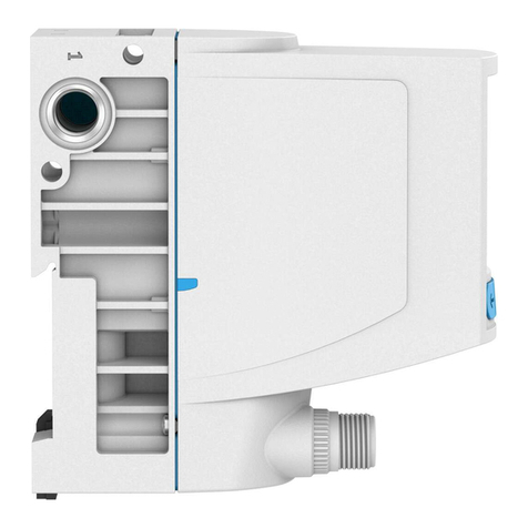
8 Technical data
General
CMMP-AS- C2-3A-M3 C5-3A-M3 C5-11A-P3-M3,
C10-11A-P3-M3
C15-11A-P3-M3
Dimensions and weight
Dimensions
(HxWxD)1)
[mm] 202x66x207 227x66x207 252x79x247
Mounting plate
dimensions
[mm] 248x61 297x75
Weight [kg] 2.1 2.2 3.5
Approvals
CE marking (see declaration
of conformity)
In accordance with EU Low Voltage Directive
In accordance with EU EMC Directive
In accordance with EU Machinery Directive
1) without plugs, screening screw and screw heads
Operating and environmental conditions
CMMP-AS- C2-3A-M3 C5-3A-M3 C5-11A-P3-M3
C10-11A-P3-M3
C15-11A-P3-M3
General
Permitted installation height above sea level
at rated output [m] 1000
with power
reduction1)
[m] 1000 … 2000 (max.)
Air humidity [%] 0 … 90 (non-condensing)
Protection class IP20 (with plugged-in plug connectors at X6 and X9)
IP10 (without plugged-in plug connectors at X6 and X9)
Degree of contamination 2
Transport and storage
Temperature range [°C] -25 … +70
Operation
Operating temper
ature
[°C] 0 … +40
Operating temper
ature with power re
duction 2.5 % per K
[°C] +40 … +50
Shutdown temper
ature of power unit
heat sink
°C 100 80 80 85
1) Above 1000 m above sea level Performance reduction of 1% per 100 m
Power supply [X9]
CMMP-AS- C2-3A-M3 C5-3A-M3 C5-11A-P3-M3
C10-11A-P3-M3
C15-11A-P3-M3
Logic supply
Nominal voltage [V DC] 24 ±20 %
Nominal current1) [A] 0.55 0.65 1
Maximum current
for holding brake2)
[A] 1 2
Load supply
Number of phases 1 3
Voltage range [V AC] 100 … 230 ±10 % 230 … 480 ±10 %
Mains frequency [Hz] 50 … 60
Alternative DC
supply
[V DC] 60 … 380 60 … 700
1) plus current consumption of a holding brake and I/Os, if present
2) for higher power requirements èHardware description
I/O interface [X1]
Type Values Remark
Digital inputs/outputs
Inputs
DIN0 … DIN9
Input voltage [V] 24 active high, con
forms to
EN 61131-2
Voltage range [V] 8 … 30
Outputs
DOUT 0 … DOUT3
Output voltage [V] 24 active high, gal
vanically isolated
Voltage range1) [V] 8 … 30
+24 V Output voltage [V] 24
Max. output current [mA] 100
GND24 Voltage [V] 0Reference poten
tial for digital I/Os
1) When used as a digital input (configuration with FCT)
I/O interface [X1]
Type Values Remark
Analogue inputs/outputs
AIN0
#AINO
Entry area [V] ±10 differential –
Resolution Bit 16
Time delay [μs] 250
max. input voltage [V] 30
RI[kΩ] 30
AIN11) Entry area [V] ±10 Single-ended –
Resolution Bit 10
Time delay [μs] 250
AIN21) Entry area [V] ±10 Single-ended –
Resolution [bit] 10
Time delay [μs] 250
AMON0, AMON1 Output range [V] ±10 –
Resolution [bit] 9
Critical frequency [kHz] 1
OGND Voltage [V] 0Reference
potential
+VREF Output range [V] 0 … 10 Reference output
for setpoint
potentiometer
1) This input can also be optionally parameterised as a digital input with an 8 V switching
threshold (parametrisation with FCT).
Supported encoders [X2A]/[X2B]
Encoder type Protocol Interface
Resolver –[X2A]
Digital encoder Incremental [X2B]
Analogue encoder –[X2B]
EnDat encoder EnDat 2.1 (01/21); EnDat 2.2 (22) [X2B]
HIPERFACE encoder HIPERFACE [X2B]
Details èHardware description
Motor connection [X6]
CMMP-AS- C2-3A-M31) C5-3A-M31) C5-11A-P3-
M32)
C10-11A-P3-
M32)
C15-11A-P3
-M32)
Voltage [VAC] 0 … 270 0 … 360
Rated output [kVA] 0.5 1369
Max. power for 5
seconds
[kVA] 12612 18
1) Data for operation at 1x230 VAC [±10 %], 50 … 60 Hz
2) Data for operation at 3x400 VAC [±10 %], 50 Hz
èAll available technical data èHardware description.

Other manuals for CMMP-AS-***-M3 Series

3

Other Festo Controllers manuals

Festo ELGE-TB User manual

Festo

Festo ELGE-TB User manual

Festo VPPM-...TA-L Series User manual

Festo

Festo VPPM-...TA-L Series User manual

Festo CMMD-AS series User manual

Festo

Festo CMMD-AS series User manual

Festo SEC-AC-305-CO User manual

Festo

Festo SEC-AC-305-CO User manual

Festo VPPI D Series User manual

Festo

Festo VPPI D Series User manual

Festo CMMP-AS-***-M3 Series User manual

Festo

Festo CMMP-AS-***-M3 Series User manual

Festo CMXR-C2 Instruction Manual

Festo

Festo CMXR-C2 Instruction Manual

Festo SPC-10 Series User manual

Festo

Festo SPC-10 Series User manual

Festo MPS PA User manual

Festo

Festo MPS PA User manual

Festo CMMS-ST-C8-7 Guide

Festo

Festo CMMS-ST-C8-7 Guide

Festo EduTrainer 571849 User manual

Festo

Festo EduTrainer 571849 User manual

Festo VPPI S1D Series User manual

Festo

Festo VPPI S1D Series User manual

Festo CMSX-...-C-U-F1 series User manual

Festo

Festo CMSX-...-C-U-F1 series User manual

Festo CHB-C-N Parts list manual

Festo

Festo CHB-C-N Parts list manual

Festo CMMP Series Operating and installation instructions

Festo

Festo CMMP Series Operating and installation instructions

Festo SFC-LAC Series Reference guide

Festo

Festo SFC-LAC Series Reference guide

Festo CPX-FEC Parts list manual

Festo

Festo CPX-FEC Parts list manual

Festo CMMO-ST-C5-1-LKP User manual

Festo

Festo CMMO-ST-C5-1-LKP User manual

Festo CPX-CMPXC-1-H1 Parts list manual

Festo

Festo CPX-CMPXC-1-H1 Parts list manual

Festo VPPI D Series Assembly instructions

Festo

Festo VPPI D Series Assembly instructions

Festo SFC-DC series User manual

Festo

Festo SFC-DC series User manual

Festo SEC-AC-305 User manual

Festo

Festo SEC-AC-305 User manual

Festo SPC200 Series User manual

Festo

Festo SPC200 Series User manual

Festo CMMP-AS Series Reference guide

Festo

Festo CMMP-AS Series Reference guide

Popular Controllers manuals by other brands

ABB i-bus KNX product manual

ABB

ABB i-bus KNX product manual

Seneca S6001 user manual

Seneca

Seneca S6001 user manual

Axis ArgusF7Pro/65AStack manual

Axis

Axis ArgusF7Pro/65AStack manual

Seada DS2 user guide

Seada

Seada DS2 user guide

Precision Digital Corporation ProtEX-MAX PD8-6310-WM instruction manual

Precision Digital Corporation

Precision Digital Corporation ProtEX-MAX PD8-6310-WM instruction manual

Alicat Scientific MC Series Installation & maintenance instructions

Alicat Scientific

Alicat Scientific MC Series Installation & maintenance instructions

Seltron SGC26 manual

Seltron

Seltron SGC26 manual

Cypress CapSense CY8C21x34/B Design guide

Cypress

Cypress CapSense CY8C21x34/B Design guide

Technische Alternative UVR610 installation instructions

Technische Alternative

Technische Alternative UVR610 installation instructions

Smartgen HGM1790N user manual

Smartgen

Smartgen HGM1790N user manual

Danfoss VLT MCD 201 installation guide

Danfoss

Danfoss VLT MCD 201 installation guide

ControlChips CY545 manual

ControlChips

ControlChips CY545 manual

Seneca Z-PASS2-RT installation manual

Seneca

Seneca Z-PASS2-RT installation manual

Siemens Simatic S7-1500R System manual

Siemens

Siemens Simatic S7-1500R System manual

motortronics VMX-agility quick start guide

motortronics

motortronics VMX-agility quick start guide

CRC CRC-RPM user manual

CRC

CRC CRC-RPM user manual

Omron E5AR user manual

Omron

Omron E5AR user manual

Regin REGIO MINI RC-DO Instruction

Regin

Regin REGIO MINI RC-DO Instruction

manuals.online logo
manuals.online logoBrands
  • About & Mission
  • Contact us
  • Privacy Policy
  • Terms and Conditions

Copyright 2025 Manuals.Online. All Rights Reserved.