manuals.online logo
Brands
  1. Home
  2. •
  3. Brands
  4. •
  5. Festo
  6. •
  7. Controllers
  8. •
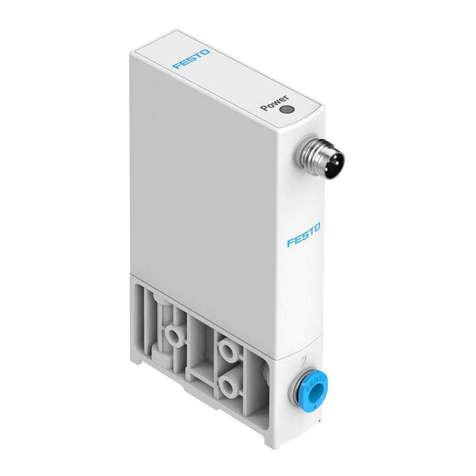
  9. Festo MPPES Series User manual

Festo MPPES Series User manual

Bedienungsanleitung
Proportional-Druckregelventil
Typ MPPES-...
Operating instructions
Proportional pressure
regulator type MPPES-...
Einbau und Inbetriebnahme nur durch
qualifiziertes Fachpersonal, gemäß Be-
dienungsanleitung.
Fitting and commissioning to be carried
out by qualified personnel only in ac-
cordance with the operating instructions.
Es bedeuten:/Symbols:
Warnung
Warning, Caution
Hinweis
Note
Recycling
Recycling
Zubehör
Accessories
393 318
9904NH D/GB 1
1
Fig. 1
Bedienteile und Anschlüsse
Druckluftanschluß (Druckeingang)
1
Arbeitsluftanschluß (Druckausgang)
2
Entlüftungsanschluß
3
Elektrischer Anschluß
4
Durchgangsbohrungen
zur Befestigung
5
Funktionserdungs-Anschluß
6
Funktion und Anwendung
Ein integrierter Drucksensor nimmt den
Druck am Arbeitsluftanschluß auf. Die
Regelelektronik vergleicht den Druck-
wert mit dem Sollwert. Dem Ausgangs-
druck entsprechend wird ein analoges,
elektrisches Signal ausgegeben. Bei
Soll-Ist-Abweichungen wird das Regel-
ventil solange betätigt, bis der Aus-
gangsdruck den Sollwert erreicht.
Das MPPES-... dient bestimmungsge-
mäß zum Regeln eines Druckes propor-
tional zu einem vorgegebenen, elektri-
schen Sollwert.
Operating parts and
connections
Compressed air connection (Input)
1
Working air connection (Output)
2
Exhaust connection
3
Electrical connection
4
Through holes for fastening
5
Functional earth connection
6
Method of operation and
application
An integrated pressure sensor records
the pressure at the working air connec-
tion. The electronic control compares the
pressure value with the nominal value.
An electrical signal is then transmitted
proportional to the output pressure. If the
nominal and actual values differ, the re-
gulating valve will be actuated until the
output pressure is the same as the no-
minal value.
The MPPES-... has been designed for
regulating the pressure proportional to
a specified electrical nominal value.
2
51
3
2
4
6
MPPES-...-1/4-...
MPPES-...-1/2-...
5
1
3
2
4
6
MPPE-...-1/8-...
MPPES-...
9904NH D/GB 2
•Stellen Sie sicher, daß hochfrequen-
te Einstrahlungen (z.B. durch Funk-
geräte, Handtelefone oder sonstige
störaussendende Geräte) vom
MPPES-... ferngehalten werden.
So vermeiden Sie erhöhte Toleran-
zen des Ausgangsdrucks (vgl. hierzu
die Angaben zur EMV im Kapitel
Technische Daten).
Voraussetzungen für den
Produkteinsatz
Allgemeine, stets zu beachtende Hin-
weise für den ordnungsgemäßen und si-
cheren Einsatz des Produkts:
•Halten Sie die angegebenen Grenz-
werte ein (z.B. für Drücke, Kräfte,
Momente, Temperaturen und elektri-
sche Spannungen).
•Sorgen Sie für ordnungsgemäß auf-
bereitete Druckluft (nach Fig. 2).
•Berücksichtigen Sie die vorherr-
schenden Umgebungsbedingungen.
•Make sure that high-frequency
interference sources (e.g. walkie-
talkies,hand telephones or other non-
suppressed devices) are kept at a
safe distance form the MPPES-... .
In this way you can avoid increased
tolerances of the output pressure
(compare the EMC specifications in
the section "Technical specifications).
Safety conditions
These general conditions for the correct
and safe use of the product must be ob-
served at all times.
•Please observe the limits e.g. for
pressures, forces, moments, tempera-
tures and electrical voltages.
•Please ensure that there is a supply
of correctly prepared compressed air
(as per Fig. 2).
•Please observe the prevailing am-
bient conditions.
3
LF-... LR-...
Fig. 2
C%mbar
Fig. 3
9904NH D/GB 3
•Beachten Sie die Vorschriften der Be-
rufsgenossenschaft, des Technischen
Überwachungsvereins oder entspre-
chende nationale Bestimmungen.
•Entfernen Sie alle Transportvorkeh-
rungen wie Schutzwachs, Folien,
Kappen, Kartonagen (mit Ausnahme
der Verschlußelemente in den pneu-
matischen Anschlüssen).
Die Entsorgung der einzelnen Werk-
stoffe in Recycling-Sammelbehälter
ist möglich.
•Belüften Sie Ihre gesamte Anlage
langsam (z.B. nach Bild 4).
Dann treten keine unkontrollierten
Bewegungen auf.
•Berücksichtigen Sie die Warnungen
und Hinweise
- am Produkt
- in dieser Bedienungsanleitung.
•Verwenden Sie das Produkt im Origi-
nalzustand ohne jegliche eigenmäch-
tige Veränderung.
•Please comply with national and
local safety laws and regulations.
•Remove all packaging such as pro-
tective wax, foils, caps and card-
board (except the protective devices
of the pneumatic connections).
The individual materials can be dis-
posed of in recycling containers.
•Slowly pressurize the complete
system (e.g. as per Fig. 4).
This will prevent sudden uncontrolled
movements from occurring.
•Please observe any warning and
instructions given
- on the product
- in these operating instructions.
•Unauthorized product modification is
not permitted.
Fig. 4
MPPES-...
9904NH D/GB 4
Einbau
Mechanisch
•Behandeln Sie das MPPES-... so,
daß keine Schäden am elektrischen
Anschluß auftreten.
Diese führen zur Minderung der
Funktionssicherheit.
•Achten Sie auf genügend Platz für
den Kabelanschluß und die
Schlauchanschlüsse.
Dadurch wird ein Abknicken des
Anschlußkabels vermieden.
•Plazieren Sie das MPPES-...
möglichst nahe am Zylinder.
Dies führt zu besserer Regelgenauig-
keit und kürzeren Ansprechzeiten.
•Schieben Sie Schrauben zur Befesti-
gung in beide Bohrungen
5
.
•Befestigen Sie das MPPES-... an
der vorgesehenen Stelle.
Fitting
Mechanical
•Take care when handling the
MPPES-... so that no damage can
occur to the electrical connections.
Damage could impair reliable opera-
tion.
•Ensure that there is sufficient space
for the cable and tubing connections.
In this way the cable will not be bent.
•Place the MPPES-... as near to the
cylinder as possible.
This will ensure more accurate con-
trol and shorter response times.
•Insert screws in both through holes
5
for fastening.
•Fasten the MPPES-... to the position
intended.
Fig. 6
Fig. 5
4
9904NH D/GB 5
Pneumatisch
•Entfernen Sie die Verschlußelemente
an den Druckluftanschlüssen.
•Verschlauchen Sie folgende
Anschlüsse:
- Druckluftanschluß
1
- Arbeitsluftanschluß
2
.
•Drehen Sie einen Schalldämpfer
(siehe Zubehör) in den Entlüftungs-
anschluß
3
.
Elektrisch
•Lesen Sie das Typenschild ab.
Folgende Ventilvarianten werden
darauf unterschieden (siehe Fig. 7).
•Verwenden Sie nur Netzteile, die
eine sichere elektrische Trennung
der Betriebsspannung nach IEC 742/
EN 60742/VDE 0551 mit mindestens
4 kV Isolationsfestigkeit gewährlei-
sten (Protected Extra-Low Voltage,
PELV).
Schaltnetzteile sind zulässig, wenn
sie die sichere Trennung im Sinne
der EN 60950/VDE 0805 gewähr-
leisten.
Pneumatic
•Remove the protective devices from
the pneumatic connections.
•Fit the tubing to the following
connections:
- compressed air connection
1
- working air connection
2
.
•Screw a silencer (see Accessories)
into the exhaust connection
3
.
Electrical
•Read the type plate.
A distinction is made here between the
following types of valves (see Fig. 7).
•Use only power units which guaran-
tee reliable isolation of the opera-
ting voltages as per IEC 742/
EN 60742/VDE 0551 with at least
4 kV isolation resistance (protected
extra low voltage, PELV).
Switch power packs are permitted if
they guarantee reliable isolation in
accordance with EN 60950/
VDE 0805.
Bezeichnung
auf
Typenschild
MPPES-
...-010 MPPES-
...-420
Benennung Spannungs-
variante Strom-
variante
Elektrischer
Sollwert DC 0...10 V 4...20 mA
Fig. 7
Designation
on type pate MPPES-
...-010 MPPES-
...-420
Name Voltage
variant Current
variant
Nominal
electrical
value
DC 0...10 V 4...20 mA
Fig. 7
MPPES-...
9904NH D/GB 6
•Prüfen Sie die Nutzung des Span-
nungs- bzw.Strom-Istwertsignals am
MPPES-....
•Verwenden Sie folgendes Anschluß-
zubehör (siehe Kapitel Zubehör):
- Dose mit Kabel oder
- Anschlußdose und
abgeschirmtes Kabel
•Verkabeln Sie folgende Anschlüsse
mit Erdpotential:
- die Abschirmung am MPPES-
fernen Kabelende.
- den Funktionserdungsanschluß
6
Dadurch ist gewährleistet, daß die
vorgegebene Schutzart IP65 und
EMV erreicht wird.
•Stellen Sie sicher, daß die Kabel
folgendermaßen verlegt sind:
- quetschfrei
- knickfrei
- dehnungsfrei.
•Check to see if the measurement of
the nominal voltage/current value sig-
nal can be used on the MPPES-...
•Use the following accessories
(see Accessories):
- socket with cable or
- connection socket and
screened cable.
•Connect the following to earth
- screening at the opposite end of
the cable from the MPPES-... .
- the functional earth connection
6
This ensures compliance with the
specified protection class IP65 and
EMC.
•Ensure that the cables are:
- not squashed
- not bent
- cannot be stretched.
Fig. 8a
6
Fig. 8
9904NH D/GB 7
•Verkabeln Sie das MPPES-... gemäß
einem der Anschlußbilder 9 oder 10:
•Connect the MPPES-... according to
one of the connection diagrams 9 or 10:
Fig. 11
Pin
Uv
Gnd
w
GND
0..10 V
x
7
3
4
2
6
8
GND
V
Fig. 9: Spannungsvariante / Voltage variant
Pin
Uv
Gnd
w
GND
x
7
3
4
2
6
8
GND
A
4..20 mA
max. 300 Ω
Fig. 10: Stromvariante /Current variant
Pin-
Nr. Spannungsvariante Stromvariante Kabelfarbe bei Verwendung der Dose
mit Kabel Typ KMPPE-... laut Zubehör
1--- --- WH weiß
2 *) Masse Sollwert *) BN braun
3 *) Masse Versorgung *) GN grün
4Sollwert DC 0...10 V Sollwert 4...20 mA YE gelb
5--- GY grau
6Istwert - Ausgang
DC 0...10 V Istwert - Ausgang
4...20 mA PK pink
7DC 24 V-Versorgungsspannung RD rot
8*) Masse Istwert *) BU blau
Fig. 12
*) Intern verbunden
MPPES-...
9904NH D/GB 8
Inbetriebnahme
1. Bestromen Sie das MPPES-... mit
Gleichstrom (Versorgungsspannung
Uv= DC 24 V).
2. Belüften Sie das MPPES-... mit einem
höheren Eingangsdruck als der maxi-
mal gewünschte Ausgangsdruck.
3. Bestromen Sie das MPPES-... mit ei-
nem Sollwertsignal entsprechend dem
Ventiltyp (Strom-/Spannungsvariante).
Es stellt sich ein dazu proportionaler
Ausgangsdruck Psein.
Commissioning
1. Apply DC voltage to the MPPES-...
(supply voltage Vv= DC 24 V).
2. Pressurize the MPPES-... with a
higher input pressure than the
maximum desired output pressure.
3. Apply a nominal value signal to the
MPPES-... according to the valve
variant (voltage variant/current variant).
A corresponding proportional output
pressure Ps will then be set.
Pin
no. Voltage variant Current variant Cable colour when used with
socket with cable type
KMPPE-... as per accessories
1--- --- WH white
2 *) Mass nominal value *) BN brown
3 *) Mass supply *) GN green
4Nominal value DC 0...10 V Nominal value 4...20 mA YE yellow
5--- GY grey
6Actual value-output 0...10 V Actual value-output
4...20 mA PK pink
7DC 24 V-supply voltage RD red
8 *) Mass actual value *) BU blue
Fig. 12
*) Intern connected
Fig. 13
5
Fig. 11
9904NH D/GB 9
Dem Sollwertsignalbereich DC
0...10 V bzw. 4...20 mA sind je nach
Bauart folgende Druckbereiche zu-
geordnet (siehe Fig. 15):
Depending on the type of valve, the
following pressure ranges are as-
signed to the nominal value signal
range DC 0...10 V or 4...20 mA (see
Fig. 15): I
1,5
010 [V]
4
[bar] P
7
2
MPPES-3-1/2-1,5-7-420
MPPES-3-1/4-2-010
20 [mA]
Fig. 14
Typ Sollwert-
Signal-
bereich
Druck-
bereich
MPPES-...-
(Pu)-Po-010 DC 0...10 V Pu... Pobar
MPPES-...-
(Pu)-Po-420 4...20 mA Pu... Pobar
z. B. Standardversion
MPPES-1/4-
2-010 DC 0...10 V 0...2 bar
z. B. Sonderabgleich
MPPES-1/2-
1,5-7-420 4...20 mA 1,5...7 bar
Fig. 15
Type Nominal
value
signal range
Pressure
range
MPPES-...-
(Pu)-Po-010 DC 0...10 V Pu... Pobar
MPPES-...-
(Pu)-Po-420 4...20 mA Pu... Pobar
e. g. standard version
MPPES-1/4-
2-010 DC 0...10 V 0...2 bar
e. g. special version
MPPES-1/2-
1.5-7-420 4...20 mA 1.5...7 bar
Fig. 15
MPPES-...
9904NH D/GB 10
Zur Sichtkontrolle des Regelvorgangs
am MPPES-...:
•Verkabeln Sie das MPPES-... mit fol-
gendem Meßgerät nach Fig. 17/18:
Auf der Anzeige des Meßgeräts kann
der elektrische Istwert verfolgt wer-
den. Dieser ändert sich proportional
zum Druckverlauf am Anschluß
2
.
In order to check the control procedure
with MPPES-...:
•connect the MPPES-... with the fol-
lowing measuring instrument (see
Fig. 17/18):
The electrical actual value can be fol-
lowed on the measuring instrument
display. This changes proportionally
to the pressure at connection
2.
Fig.17:
Spannungs-
meßgerät
Voltage
measuring
instrument
Fig. 18:
Strommeßgerät
Current measuring
instrument
Spannungsvariante Stromvariante
Spannungsmeßgerät Strommeßgerät
Fig. 16
Voltage variant Current variant
Voltage measuring
instrument Current measur-
ing instrument
Fig. 16
9904NH D/GB 11
Bedienung und Betrieb
Bei anhaltend gleichem Ausgangsdruck
trotz veränderter Sollwertvorgabe:
•Schauen Sie nach schadhaften
Kabeln.
Bei Bruch von Sollwertkabeln (nur
MPPES-...-420B) oder Versorgungs-
kabeln geht der Ausgangsdruck auf
0 bar zurück.
Bei Verwendung des MPPES-...-10-...:
•Stellen Sie sicher, daß der Magnet-
kopf gegen direkte Berührung gesi-
chert ist.
Die Temperatur des Magnets kann im
Dauerbetrieb bis über + 70 °C an-
steigen.
Ausbau und Reparatur
Zum Ausbau:
•Schalten Sie folgende Energien ab:
- Druckluft
- Spannungsversorgung
Operation
If the output pressure remains constant
despite modified nominal value,
•examine the cables for damage.
If there is a fracture in the nominal
value cable (with MPPES-...-420B) or
in the supply voltage cables, the out-
put pressure will reduce to 0 bar.
If you use the MPPES-...-10-...:
•make sure that the magnet head is
protected against direct contact.
The temperature of the magnet can
rise to over + 70 °C during continous
operation.
Dismantling and repairs
Dismantling:
•Switch off the following
- compressed air
- voltage supply
6
7
MPPES-...
9904NH D/GB 12
Störungsbeseitigung
8
Störung Mögliche Ursache Abhilfe
MPPES-...
reagiert nicht Versorgungsspannung fehlt Versorgungsspannung DC 24 V, Anschluß überprüfen
Sollwertspannung fehlt Steuergerät überprüfen, Anschluß überprüfen
Eingangsdruck PEnicht vorhanden Eingangsdruck über den gewünschten Sollwertdruck erhöhen. Der
Eingangsdruck muß kleiner als der maximal zulässige Wert sein
(siehe Technische Daten).
MPPES-... defekt MPPES-... zu Festo einschicken
Durchflußmenge
zu gering Verengung des Strömungsquerschnitts durch
Anschlußtechnik (Schwenkverschraubungen,
Schalldämpfer zu klein)
Anschlußalternativen einsetzen
Fig. 19
Eliminating faults
Fault Possible cause Remedy
MPPES-... does
not react Supply voltage not applied Supply voltage DC 24 V, check connection
Nominal value voltage not applied Check controller, check connection
Input pressure PEdoes not exist Increase input pressure above the desired nominal value pressure.
The input pressure must be lower than the maximum permitted
value (see Technical Specifications).
MPPES-... defective Return MPPES-... to Festo
Flow too small Restriction of flow cross section due to
connections (swivel fittings, silencer too small) Use other connections
Fig. 19
9904NH D/GB 13
9Technische Daten
Bauart Proportional-Druckregelventil
Einbaulage Beliebig, vorzugsweise senkrecht (Proportionalmagnet nach oben)
Medium Gefilterte, geölte oder ungeölte Druckluft (Filterfeinheit min. 40 µm)
Arbeitsdruck Konstant (unabhängig von Schwankungen der Druckluftversorgung).
Eingangsdruck min. 1 bar höher als max. Ausgangsdruck.
Schutzart IP65 in Verbindung mit Anschlußdose laut Zubehör
Zul. Temperaturbereich Umgebung: 0...+ 50 °C Lagerung: - 20...+ 70 °C Medium: 0...+ 60 °C
Zul.Versorgungsspannung DC + 18... max. 30 V (Nennwert: DC + 24 V)
Leistungsaufnahme (bei Uvmax = DC 30 V) Max. 20 W (bei MPPES-2-... und bei MPPES-6-...) max. 30 W (bei MPPES-10-...)
EMV: Störfestigkeit nach DIN EN 50082-2
Störaussendung nach DIN EN 50081-1
Bei elektomagnetischem HF-Feld nach ENV 50140 gilt folgende minimale Betriebsqualität:
- Spannungsvariante: ±
0,2 bar
- Stromvariante: ±0,1 bar
Linearität < 0,5 % Full Scale
Elektrischer Anschluß Steckkontakt 8polig nach DIN 45326
Auflösung des Istwertausgangs 8 Bit (ca. 40 mV bei Spannungsvariante / ca. 0,0625 mA bei Stromvariante)
Sicherheitsstellung Bei Kabelbruch der Versorgungsspannung sowie Sollwertkabelbruch geht der Ausgangsdruck
auf 0 bar zurück
Werkstoffe Gehäuse: Al, PET; Deckel: Zn-GD; Dichtungen: NBR; Schmierung: silikonfrei
Sollwertgröße:
Zul. Lastwiderstand:
Eingangswiderstand:
0...+ 10 V (Spannungsvariante) 4...20 mA (Stromvariante)
min. 2 kΩ(Spannungsvariante) max. 500 Ω(Stromvariante)
10 kΩ(Spannungsvariante) 250 Ω(Stromvariante)
Fig. 20
Allgemeine Daten
Spannungsvariante: MPPES-...-010 (Sollwert: DC 0...10 V)
Stromvariante: MPPES-...-420 (Sollwert: 4...20 mA)
MPPES-...
9904NH D/GB 14
Anschlußspezifische Daten
Typ MPPES-1/8-... MPPES-1/4-... MPPES-1/2-...
Anschlüsse 1/8 1/4 1/2
Nennweite - Belüftung/Entlüftung 3 mm/2 mm 7 mm/7 mm 11 mm/12 mm
Hysterese *) max. 10 mbar max. 50 mbar
Gewicht 0,9 g 1,3 kg 2,6 kg
Fig. 21
*) Siehe Angaben zur EMV (Allgemeine Daten)
Typ MPPES-3-1/8-10- MPPES-3-1/4-10- MPPES-3-1/2-10-
010 420 010 420 010 420
Teile-Nr. 187348 187349 187333 187334 187326 187327
Nenndurchfluß Qn6 → 5 bei p = 10 bar an 1 630 l/min. 2800 l/min. 7800 l/min.
Druckbereiche Zul. Eingangsdruck: max. 12 bar Regelbereich: 0...10 bar
Produktspezifische Daten (Teil 1)
Typ MPPES-3-1/8-6- MPPES-3-1/4-6- MPPES-3-1/2-6-
010 420 010 420 010 420
Teile-Nr. 187352 187353 187337 187338 187330 187331
Nenndurchfluß Qn6 → 5 bei p = 8 bar an 1 540 l/min. 2500 l/min. 8600 l/min.
Druckbereiche Zul. Eingangsdruck: max. 8 bar Regelbereich: 0...6 bar
Fig. 22
9904NH D/GB 15
Produktspezifische Daten (Teil 2)
Typ MPPES-3-1/8-2- MPPES-3-1/4-2- MPPES-3-1/2-2-
010 420 010 420 010 420
Teile-Nr. 187350 187351 187335 187336 187328 187329
Nenndurchfluß Qn1,2 → 1 bei p = 4 bar an 1 300 l/min. 1450 l/min. 3800 l/min.
Druckbereiche Zul. Eingangsdruck: max. 4 bar Regelbereich: 0...2 bar
Typ (Sonderabgleich) MPPES-3-1/8-Pu-Po- MPPES-3-1/4-Pu-Po- MPPES-3-1/2-Pu-Po-
010 420 010 420 010 420
Teile-Nr. 187347 187762 187339 187744 187332 187735
Nenndurchfluß QnAbhängig vom gewählten Sonderabgleich
Druckbereiche Zul. Eingangsdruck: max. (Po+ 1) bar (bei Po< 1 bar)
max. (Po+ 2) bar (bei Po> 1 bar)
Zul. Eingangsdruck: Pu... Pobar
Fig. 22
MPPES-...
9904NH D/GB 16
Technical specifications
Type Proportional pressure regulator
Fitting position As desired, preferably vertical (Proportional magnet at top)
Medium Filtered, lubricated or non-lubricated compressed air (grade of filtration min. 40 µm)
Working pressure Constant (irrespective of fluctuations in the compressed air supply).
Input pressure min. 1 bar higher than max. output pressure.
Protection class IP65 in conjunction with connecting socket as per Accessories
Permitted temperature range Ambient: 0...+ 50 °C Storage: - 20...+ 70 °C Medium: 0...+ 60 °C
Permitted supply voltage DC + 18... max. 30 V (rated value DC + 24 V)
Power consumption (at UVmax = DC 30 V) max. 20 W (at MPPES-2-... and MPPES-6-...) max. 30 W (at MPPES-10-...)
EMC:
Immunity to interference as per DIN EN 50082-2
Spark suppression as per DIN EN 50081-1
In the electromagnetic HF-field as per ENV 50140 the following applies:
Minimum operating quality: - Voltage variant: ±0.2 bar
- Current variant: ±0.1 bar
Linearity < 0.5 % full scale
Electrical connection 8-pin plug as per DIN 45326
Resolution of actual value signal 8 Bit (approx. 40 mV with voltage variant / approx. 0.0625 mA with current variant)
Backup storage If there is a fracture in the voltage supply cable or in the nominal value cable, the
ouput pressure will reduce to 0 bar.
Materials Housing: Al, PET; Cover: Zn-GD; Seals: NBR; Lubrication: silicon-free
Nominal value variable:
Permitted load resistance:
Input resistance:
0... + 10 V (voltage variant) 4...20 mA (current variant)
min. 2 kΩ(voltage variant) max. 500 Ω(current variant)
10 kΩ(voltage variant) 250 Ω (current variant)
Fig. 20
General specifications
Voltage variant: MPPES-...-010 (Nominal value: DC 0...10 V)
Current variant: MPPES-...-420 (Nominal value: 4...20 mA)
9
9904NH D/GB 17
Type MPPES-1/8-... MPPES-1/4-... MPPES-1/2-...
Connections 1/8 1/4 1/2
Size: pressurization/exhaust 3 mm/2 mm 7 mm/7 mm 11 mm/12 mm
Hysteresis *) max. 10 mbar max. 50 mbar
Weight 0.9 kg 1.3 kg 2.6 kg
Fig. 21
*) See specification EMC (general specifications)
Type MPPES-3-1/8-10- MPPES-3-1/4-10- MPPES-3-1/2-10-
010 420 010 420 010 420
Part no. 187348 187349 187333 187334 187326] 187327
Rated flow Qn6 → 5 at p = 10 bar at 1 630 l/min. 2800 l/min. 7800 l/min.
Pressure ranges: Permitted input pressure: max. 12 bar Control range: 0...10 bar
Connection specifications
Product-specific specifications (Vol I)
Type MPPES-3-1/8-6- MPPES-3-1/4-6- MPPES-3-1/2-6-
010 420 010 420 010 420
Part no. 187352 187353 187337 187338 187330 187331
Rated flow Qn6 →5 at p = 8 bar at 1 540 l/min. 2500 l/min. 8600 l/min.
Pressure ranges Permitted input pressure: max. 8 bar Control range: 0...6 bar
Fig. 22
MPPES-...
9904NH D/GB 18
Product-specific specifications (Vol II)
Type MPPES-3-1/8-2- MPPES-3-1/4-2- MPPES-3-1/2-2-
010 420 010 420 010 420
Part no. 187350 187351 187335 187336 187328 187329
Rated flow Qn1.2 → 1 at p = 4 bar at 1 300 l/min. 1450 l/min. 3800 l/min.
Pressure ranges Permitted input pressure: max. 4 bar Control range: 0...2 bar
Typ (special version) MPPES-3-M5-Pu-Po- MPPES-3-1/4-Pu-Po- MPPES-3-1/2-Pu-Po-
010 420 010 420 010 420
Part no. 187347 187762 187339 187744 187332 187735
Rated flow QnDepending on special version selected
Pressure ranges Permitted input pressure: max. (Po+ 1) bar (at Po< 1 bar)
max. (Po+ 2) bar (at Po> 1 bar)
Control range: Pu... Pobar
Fig. 22
9904NH D/GB 19
•Reinigen Sie das MPPES-...
nur mit Seifenlauge,
max. 60 °C.
•Clean the MPPES-... only with
soap suds, max. 60 °C.
Postfach
D-73726 Esslingen
Phone +49/711/347-0
Quelltext: Deutsch
Version: 9904NH
Weitergabe sowie Vervielfätigung dieses
Dokuments, Verwertung und Mitteilung
seines Inhalts verboten, soweit nicht
ausdrücklich gestattet. Zuwiderhandlun-
gen verpflichten zu Schadenersatz. Alle
Rechte vorbehalten, insbesondere das
Recht, Patent-, Gebrauchsmuster- oder
Geschmacksmusteranmeldungen durch-
zuführen.
The copying, distribution and utilization
of this document as well as the com-
munication of its contents to others with-
out expressed authorization is pro-
hibited. Offenders will be held liable for
the payment of damages. All rights
reserved, in particular the right to carry
out patent, utility model or ornamental
design registrations.
11
Bezeichnung Typ
Dose mit Kabel, 8 adrig, 2,5 m (5 m) KMPPE-2,5 (KMPPE-5)
Dose 8-polig MPPE-B
Kabel für Ventilinsel, 1 Dose 8-polig, 1 Dose 6-polig KVIA-MPPE-2,5
Schalldämpfer U-1/8; U-1/4; U-1/2
Designation Type
Socket with cable, 8-core, 2.5 m (5 m) KMPPE-2.5 (KMPPE-5)
Socket 8-pin MPPE-B
Cable for terminal, 1 socket 8-pin, 1 socket 6-pin KVIA-MPPE-2.5
Silencer U-1/8; U-1/4; U-1/2
Fig. 23
Wartung und Pflege
10
Zubehör / Accessories
Maintenance and care
9904NH D/GB 20

Other manuals for MPPES Series

1

This manual suits for next models

2

Other Festo Controllers manuals

Festo CPX-E-CEC EP Series User manual

Festo

Festo CPX-E-CEC EP Series User manual

Festo CDSA-D1-VX User manual

Festo

Festo CDSA-D1-VX User manual

Festo MPP-3-1/8 User manual

Festo

Festo MPP-3-1/8 User manual

Festo VPPM C1 Series User manual

Festo

Festo VPPM C1 Series User manual

Festo CMMO-ST-C5-1-LKP User manual

Festo

Festo CMMO-ST-C5-1-LKP User manual

Festo CMMP-AS-C5-3A-M0 Guide

Festo

Festo CMMP-AS-C5-3A-M0 Guide

Festo LR G Series User manual

Festo

Festo LR G Series User manual

Festo CMMS-ST Series Guide

Festo

Festo CMMS-ST Series Guide

Festo Controller CECC User manual

Festo

Festo Controller CECC User manual

Festo CMMS-AS G2 Series Instruction Manual

Festo

Festo CMMS-AS G2 Series Instruction Manual

Festo DFPD-Series User manual

Festo

Festo DFPD-Series User manual

Festo CMMP-AS-***-M3 Series Operating and installation instructions

Festo

Festo CMMP-AS-***-M3 Series Operating and installation instructions

Festo s CMMD-AS-C8-3A Guide

Festo

Festo s CMMD-AS-C8-3A Guide

Festo DFPD-HD-Series User manual

Festo

Festo DFPD-HD-Series User manual

Festo CMMP-AS-C2-3A User manual

Festo

Festo CMMP-AS-C2-3A User manual

Festo SPC200-SCU-AIF Parts list manual

Festo

Festo SPC200-SCU-AIF Parts list manual

Festo VEAA Assembly instructions

Festo

Festo VEAA Assembly instructions

Festo CECX-X-C1 Series User manual

Festo

Festo CECX-X-C1 Series User manual

Festo CMMO-ST-C5-1-LKP User manual

Festo

Festo CMMO-ST-C5-1-LKP User manual

Festo SPC-AIF Series User manual

Festo

Festo SPC-AIF Series User manual

Festo CMXR-C1 Operating and installation instructions

Festo

Festo CMXR-C1 Operating and installation instructions

Festo DFPD-x-RS Series User manual

Festo

Festo DFPD-x-RS Series User manual

Festo LRP-1/4 Series User manual

Festo

Festo LRP-1/4 Series User manual
Festo DAPS Series User manual

Festo

Festo DAPS Series User manual

Popular Controllers manuals by other brands

GE IC695PNC001 user manual

GE

GE IC695PNC001 user manual

Sentera Controls RDCZ Series Mounting and operating instructions

Sentera Controls

Sentera Controls RDCZ Series Mounting and operating instructions

Carrier TruVu VVTZC-E2 Installation and startup guide

Carrier

Carrier TruVu VVTZC-E2 Installation and startup guide

HydroPoint WeatherTRAK ET Pro3 2-Wire Getting started guide

HydroPoint

HydroPoint WeatherTRAK ET Pro3 2-Wire Getting started guide

Allen-Bradley 161S-AA04NPU user manual

Allen-Bradley

Allen-Bradley 161S-AA04NPU user manual

Contest PILOT-192PRO user guide

Contest

Contest PILOT-192PRO user guide

Endress+Hauser Liquiline CM442R Brief operating instructions

Endress+Hauser

Endress+Hauser Liquiline CM442R Brief operating instructions

Jetter JVM-104-O15 user manual

Jetter

Jetter JVM-104-O15 user manual

Dukane iQ Series quick start guide

Dukane

Dukane iQ Series quick start guide

Parker LUCIFER P4BG6 Series Installation and setting instructions

Parker

Parker LUCIFER P4BG6 Series Installation and setting instructions

Denali CANsmart Controller GEN II instruction manual

Denali

Denali CANsmart Controller GEN II instruction manual

Emerson AVENTICS Sentronic TWIN 615 Assembly instructions

Emerson

Emerson AVENTICS Sentronic TWIN 615 Assembly instructions

Glensound Electronics ISDN GSGC6 manual

Glensound Electronics

Glensound Electronics ISDN GSGC6 manual

SMC Networks EQFS Series Operation manual

SMC Networks

SMC Networks EQFS Series Operation manual

Danfoss ECL Comfort 296 operating guide

Danfoss

Danfoss ECL Comfort 296 operating guide

Carrier XCT7 40VCW317FQEE Installation and owner's manual

Carrier

Carrier XCT7 40VCW317FQEE Installation and owner's manual

FlowLine Thermo-Flo LC30 Series manual

FlowLine

FlowLine Thermo-Flo LC30 Series manual

Comar Condensatori HPR6 Installation and user manual

Comar Condensatori

Comar Condensatori HPR6 Installation and user manual

manuals.online logo
manuals.online logoBrands
  • About & Mission
  • Contact us
  • Privacy Policy
  • Terms and Conditions

Copyright 2025 Manuals.Online. All Rights Reserved.