manuals.online logo
Brands
  1. Home
  2. •
  3. Brands
  4. •
  5. Festo
  6. •
  7. Switch
  8. •
  9. Festo SRBE EX Series User manual

Festo SRBE EX Series User manual

Translation of the original instructions
© 2020 all rights reserved to Festo SE & Co. KG
1 Identification EX
Identification mark Certificate
International Ex db IIC T6 Gb
Ex tb IIIC T(*) Db
IECEx FTZU 15.0014X
Europe II 2G Ex db IIC T6 Gb
II 2D Ex tb IIIC T(*) Db
FTZU 15 ATEX 0095X
China Ex d IIC T6 Gb
Ex tD A21 IP67 T*
GYJ16.1497X
Tab. 1
2 Applicable documents
NOTICE!
Technical data for the product can have different values in other documents. For
operation in an explosive atmosphere, the technical data in this document always
have priority.
All available documents for the product èwww.festo.com/sp.
3 Safety
3.1 Safety instructions
– The device can be used under the stated operating conditions in zone 1,
explosive gas atmospheres, and in zone 21, explosive dust atmospheres.
– Observe the product labelling.
3.2 Intended use
The intended use of the product is to record and display the end positions and
intermediate positions of pneumatic drives.
3.3 Identification X: special conditions
–Ambient temperature: –20°C£Ta£+60°C
– Use only cable fittings or sealing plugs that are approved for the applicable
type of (ignition) protection and IP67.
– Only clean the device with a damp cloth.
– For further information on the flameproof gaps, contact the manufacturer.
4 Product overview
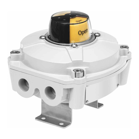
1Position indicator
2Housing cover
3Housing screws
4Shaft with cam
5Proximity switches
6Terminal strip
7Earth connection (PE) on the inside
and outside of the housing wall
8Cable inlet M20x1.5 or NPT ½
9Mounting adapter with retaining
screws M5x10
Fig. 1
Default settings on delivery:
– Position indicator “closed”
– Switching point for “open” 90° anti-clockwise
5 Additional information
– Accessories èwww.festo.com/catalogue.
– Service èwww.festo.com.
Contact the regional Festo contact if you have technical questions.
6 Function
The limit switch box is used for the detection and electrical and optical feedback
of the end positions of a drive. The limit switch box is suitable for operation with
semi-rotary drives with a mechanical interface in accordance with VDI/VDE
Guideline3845.
7 Installation
WARNING!
Carry out the commissioning, service and inspection outside of the explosive
atmosphere. Disconnect the power supply before this work and secure against
reconnection.
NOTICE!
Installation and commissioning may only be performed in accordance with the
operating instructions and by qualified personnel.
1. Close process valve.
2. Place the limit switch box with mounting adapter on the drive and align it.
– Avoid axial load of the drive shaft.
3. Fasten the mounting adapter to the drive.
– Lock the retaining screws. Tightening torque: 6 Nm ± 10%
Mounting adapter
When replacing the limit switch attachment, observe the tightening torque.
– Tightening torque between mounting adapter and limit switch box:
10 Nm ± 10%
8 Electrical connection
WARNING!
Before switching on the electrical circuit in potentially explosive atmospheres:
• Mount the cover securely on the housing.
• Connect with potential equalisation.
NOTICE!
Thread of the cable guide depends on the product variant: M20x1.5 or 1/2 NPT
Cable fittings must be appropriate for the corresponding thread type. Cable con-
nector threads must not protrude into the interior of the housing.
8141485
SRBE-...-EX
Limit Switch Box
8141485
2020-07c
[8141487]
Operating instructions
Festo SE & Co. KG
Ruiter Straße 82
73734 Esslingen
Germany
+49 711 347-0
www.festo.com
NOTICE!
The supplied plastic blanking plugs are intended exclusively for protection
against contamination during transport and handling. During operation, these
should be replaced by cable connectors and/or blanking plugs approved for use
in explosion protection areas.
WARNING!
Use cable connectors of type of (ignition) protection Ex-d and a degree of protec-
tion of at least IP67. Seal unused cable entries with blanking plugs.
1. Loosen the housing screws3on the housing cover2.
2. Screw the cable fitting into the cable inlet8. Guide the electrical connecting
cable through the cable fitting to the terminal block6.
3. Wiring connections è 8.1 Terminal plan
4. Connect the earth terminal7 with low impedance (short cable with large
cross section) to the earth terminal.
5. Place the housing cover in position and tighten the housing screws.
– Note the correct position of the seal.
8.1 Terminal plan
SRBE-Cxx-YR90-MW-22A-1W-…/SRBE-Cxx-YR90-R-2A-1W-…
Fig. 2 Two SPDT micro-switches, mechanical or magnetic
SRBE-Cxx-YR90-N-20N-ZC-…/SRBE-Cxx-YR90-N-1-ZU-…
Fig. 3 Two-wire proximity switches, inductive
SRBE-Cxx-YR90-N-1-P-…/SRBE-Cxx-YR90-N-1-N-…
Fig. 4 Three-wire proximity switches, inductive
SRBE-Cxx-YR90-MW-22A-2W-…
Fig. 5 Four SPDT micro-switches, mechanical
9 Switching point adjustment
The switching points are preset è 4 Product overview.
Fig. 6
1. Close process valve.
ÄPosition indicator: “closed”.
2. Loosen the housing screws on the housing cover and remove the housing
cover.
3. Lift the red cam against the spring and turn until the lower proximity switch
switches.
4. Release the red cam.
Ä– The spring presses the red cam into the ring gear.
– The switching point for “closed” is set.
5. Open process valve.
ÄPosition indicator: “open”.
6. Press down the green cam against the spring and turn until the upper proxim-
ity switch switches.
7. Release the green cam.
Ä– The spring presses the green cam into the ring gear.
– The switching point for “open” is set.
8. Place the housing cover in position and tighten the housing screws.
10 Maintenance and care
The device is maintenance-free. Repairs are not possible.
Avoid contact with aggressive substances.
– Only clean the device with a damp cloth. Do not use the following agents:
– Abrasives
– Alcohol
– Solvents
– Protect surfaces from excessive heat.
11 Fault clearance
Fault description Cause Remedy
Wire break Replace cable
Position of the switching points
incorrect
Setting switching points
Incorrect or unexpected signal
Proximity switch defective Replace limit switch box
Tab. 2
12 Technical data
SRBE-...
Angular detection setting range [°] 0…90
Cable entry
SRBE-…-M20 2 x M20x1.5
SRBE-…-N12 2 x 1/2 NPT
Electrical connection
SRBE-Cxx-YR90-MW-22A-1W-…
SRBE-Cxx-YR90-N-20N-ZC-…
SRBE-Cxx-YR90-N-1-P-…
SRBE-Cxx-YR90-N-1-N-…
SRBE-Cxx-YR90-N-1-ZU-…
SRBE-Cxx-YR90-R-2A-1W-…
10-pin, screw terminal
SRBE-Cxx-YR90-MW-22A-2W-… 14-pin, screw terminal
Conductor nominal cross section that
can be connected
[mm²] 0.25…2.5
Mounting position any
Operating voltage range AC
SRBE-Cxx-YR90-R-2A-1W-… [V] 0…220
SRBE-Cxx-YR90-MW-22A-1W-…
SRBE-Cxx-YR90-MW-22A-2W-…
[V] 0…250
Max. output current AC
SRBE-Cxx-YR90-R-2A-1W-… [A] 0.416 (220 V)
SRBE-Cxx-YR90-MW-22A-1W-…
SRBE-Cxx-YR90-MW-22A-2W-…
[A]
[V]
3 (250 V)
Operating voltage range DC
SRBE-Cxx-YR90-R-2A-1W-…
SRBE-Cxx-YR90-MW-22A-1W-…
SRBE-Cxx-YR90-MW-22A-2W-…
[V] 0…30
SRBE-Cxx-YR90-N-20N-ZC-… [V] 8.2
SRBE-Cxx-YR90-N-1-P-…
SRBE-Cxx-YR90-N-1-N-…
[V] 10…30
SRBE-Cxx-YR90-N-1-ZU-… [V] 5…60
Max. output current DC
SRBE-Cxx-YR90-R-2A-1W-… [A] 3 (300 V)
SRBE-...
SRBE-Cxx-YR90-MW-22A-1W-…
SRBE-Cxx-YR90-MW-22A-2W-…
[A] 6 (30 V); 0.6 (125 V); 0.3 (250 V)
SRBE-Cxx-YR90-N-20N-ZC-… [mA] 3
SRBE-Cxx-YR90-N-1-P-…
SRBE-Cxx-YR90-N-1-N-…
SRBE-Cxx-YR90-N-1-ZU-…
[mA] 100
Voltage drop
SRBE-Cxx-YR90-N-1-P-…
SRBE-Cxx-YR90-N-1-N-…
[V] £3
SRBE-Cxx-YR90-N-1-ZU-… [V] £5
Residual current
SRBE-Cxx-YR90-N-1-P-…
SRBE-Cxx-YR90-N-1-N-…
[mA] £15
No-load supply current
SRBE-Cxx-YR90-N-1-P-…
SRBE-Cxx-YR90-N-1-N-…
[mA] 0…0.5
SRBE-Cxx-YR90-N-1-ZU-… [mA] 0…1
Reverse polarity protection
SRBE-Cxx-YR90-N-1-P-…
SRBE-Cxx-YR90-N-1-N-…
SRBE-Cxx-YR90-N-1-ZU-…
For all electrical connections
Short circuit current rating
SRBE-Cxx-YR90-N-1-P-…
SRBE-Cxx-YR90-N-1-N-…
Pulsed
Ambient temperature EX [°C] –20…+60
Max. surface temperature T(*) limit switch box
SRBE-Cxx-YR90-MW-22A-1W-…
SRBE-Cxx-YR90-MW-22A-2W-…
SRBE-Cxx-YR90-N-1-ZU-…
[°C] T75
SRBE-Cxx-YR90-N-1-P-…
SRBE-Cxx-YR90-N-1-N-…
SRBE-Cxx-YR90-N-20N-ZC-…
SRBE-Cxx-YR90-R-2A-1W-...
[°C] T61
Degree of protection IP67, NEMA 4/4X
Continuous shock resistance to DIN/IEC
68 Part 2-82
±15g at 6 ms duration;
1000 shocks per direction
Vibration resistance to DIN/IEC 68 Part
2-6
0.35 mm path at 0…60 Hz;
5 g acceleration at 0…150 Hz
Materials
Housing Painted die-cast aluminium
Shaft high-alloy stainless steel
Seal NBR
Screws high-alloy stainless steel
Optical position indicator PC
Mounting adapter high-alloy stainless steel
Tab. 3

Other Festo Switch manuals

Festo VABF-S4-A2G2 Series User manual

Festo

Festo VABF-S4-A2G2 Series User manual

Festo SOEL-RTH-Q20 User manual

Festo

Festo SOEL-RTH-Q20 User manual

Festo DAPZ AR Series User manual

Festo

Festo DAPZ AR Series User manual

Festo PEV-1/4A-SW27-B-OD User manual

Festo

Festo PEV-1/4A-SW27-B-OD User manual

Festo SMT-10G-...-24V Series User manual

Festo

Festo SMT-10G-...-24V Series User manual

Festo PEV-1/4-B-OD User manual

Festo

Festo PEV-1/4-B-OD User manual

Festo SRBF-C series User manual

Festo

Festo SRBF-C series User manual

Festo VPEV-1/8 User manual

Festo

Festo VPEV-1/8 User manual

Festo PEV-1/4-B User manual

Festo

Festo PEV-1/4-B User manual

Festo SMT-8M-A-...-24V-E Series User manual

Festo

Festo SMT-8M-A-...-24V-E Series User manual

Festo CDSM-S3-P User manual

Festo

Festo CDSM-S3-P User manual

Festo Compact Performance CP-FB6-E Quick guide

Festo

Festo Compact Performance CP-FB6-E Quick guide

Festo SME-1-B User manual

Festo

Festo SME-1-B User manual

Festo PEV-1/4-B-M12 User manual

Festo

Festo PEV-1/4-B-M12 User manual

Festo SMEO-4 Series User manual

Festo

Festo SMEO-4 Series User manual

Festo DAPZ AR Series User manual

Festo

Festo DAPZ AR Series User manual

Festo SME-1 Series User manual

Festo

Festo SME-1 Series User manual

Festo PENV O-S-L-GH Series User manual

Festo

Festo PENV O-S-L-GH Series User manual

Festo CAMC-G-S Series User manual

Festo

Festo CAMC-G-S Series User manual

Festo SME-CDC-DS-24V-SQM8 User manual

Festo

Festo SME-CDC-DS-24V-SQM8 User manual

Festo SRBE Series User manual

Festo

Festo SRBE Series User manual

Festo SMTO-1 C Series User manual

Festo

Festo SMTO-1 C Series User manual

Festo SMTO-4 Series User manual

Festo

Festo SMTO-4 Series User manual

Festo PE-PK Series User manual

Festo

Festo PE-PK Series User manual

Popular Switch manuals by other brands

GE GuardSwitch 300 Series quick start guide

GE

GE GuardSwitch 300 Series quick start guide

Cabletron Systems SmartSTACK 100 user guide

Cabletron Systems

Cabletron Systems SmartSTACK 100 user guide

EUCHNER CES-I-BP Series operating instructions

EUCHNER

EUCHNER CES-I-BP Series operating instructions

Veris Industries Hawkeye 939 installation guide

Veris Industries

Veris Industries Hawkeye 939 installation guide

Supermicro SSE-G48-TG4 Configuration guide

Supermicro

Supermicro SSE-G48-TG4 Configuration guide

NIVELCO NIVOFLIP MAK-100 Series user manual

NIVELCO

NIVELCO NIVOFLIP MAK-100 Series user manual

FM Systems VLS771-2 installation manual

FM Systems

FM Systems VLS771-2 installation manual

INNOVATIVE CIRCUIT TECHNOLOGY ICT200-LVD instruction manual

INNOVATIVE CIRCUIT TECHNOLOGY

INNOVATIVE CIRCUIT TECHNOLOGY ICT200-LVD instruction manual

TRENDnet TPE-S44 - Switch Quick installation guide

TRENDnet

TRENDnet TPE-S44 - Switch Quick installation guide

EUCHNER TZ AS1 Series operating instructions

EUCHNER

EUCHNER TZ AS1 Series operating instructions

Eaton EGS Series Instruction booklet

Eaton

Eaton EGS Series Instruction booklet

HP P2361AA #ABA user manual

HP

HP P2361AA #ABA user manual

Key Digital KD-X4x1WUTx operating instructions

Key Digital

Key Digital KD-X4x1WUTx operating instructions

ANTAIRA LNP-2602G-SFP Series Quick installation guide

ANTAIRA

ANTAIRA LNP-2602G-SFP Series Quick installation guide

Cisco AJ732A -  MDS 9134 Fabric Switch installation guide

Cisco

Cisco AJ732A - MDS 9134 Fabric Switch installation guide

NETGEAR S350 Series installation guide

NETGEAR

NETGEAR S350 Series installation guide

IPGARD DPMST-4S-P quick start guide

IPGARD

IPGARD DPMST-4S-P quick start guide

Intermatic CA600 user manual

Intermatic

Intermatic CA600 user manual

manuals.online logo
manuals.online logoBrands
  • About & Mission
  • Contact us
  • Privacy Policy
  • Terms and Conditions

Copyright 2025 Manuals.Online. All Rights Reserved.