manuals.online logo
Brands
  1. Home
  2. •
  3. Brands
  4. •
  5. Festo
  6. •
  7. Switch
  8. •
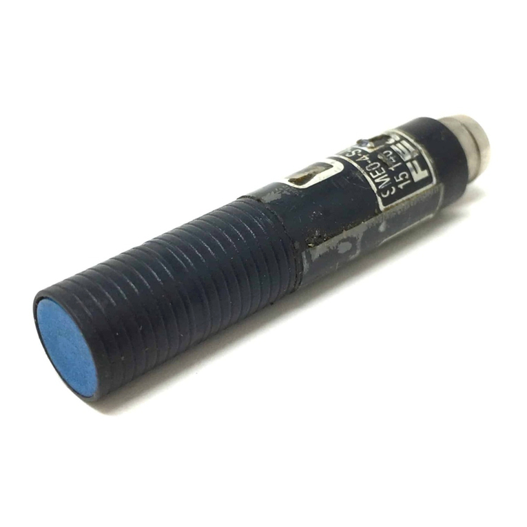
  9. Festo SMEO-2 Series User manual

Festo SMEO-2 Series User manual

372 615
Operating Instructions
Bedienungsanleitung
Electrical Reed Switch
Naherungsschalter
Type SMEO-2
Typ SMEO-2
with additional yellow LED
TypeSMEO-2-LED-24
mit
zus&zlicher
gelber
Leuchtdiode
TypSMEO-2-LED-24
Conditions regarding the use of Festo
equipment.
This.is
important for reasons of safety
WasistbeimEinsatz vonFesto Elementenzu
beachten?
D,e
Elnhaltung
der
~ewe~ls
angegebenen
Grenzwerte
ftir
Drticke,
Spannungen,
Temperaturen
und
de
Bexhtung
van
H~nwase”
1st
Voraussetzung
ftir die
ordnungsgem%e
Funktlon
und
daher
vom
Anwender
unbedingt
zt.
gewtihr-
l&ten
,,
,t
,S
,ncM
,rn~~kW
that only properly Instructed and
quaIlfled
personneluse
this
equipment.
2,
This
equipment
should only be used
withIn
the
llmlts
detaIled
in the technical
spraficatlon.
Strict
observance
of the
technIcal
speclficatlon
should be
e”sureU
at all
t,mes.
3,
Correctly prepared
compre?.sed
ar
should
be used at
all
t~rnes.
When
mstall~ng
the equipment and thereafter, the
Customer shall
ensure
that the environmental
ccmdrt~ons
at the
place
of use are taken into
corwderation.
4,
If the
eqwprnent
1s
mcorporated
in
a
system or used
wthmsafetydev~cesorcIrcuit%
theCustomwshal1
ensure
that
national
and local safety
laws
and
regulations
are
observed.
5,
Should
you
req”,re
further
x”format\on
please contact
your local
F&o
office
These instructions
are
important. Please keep them in
a
safe
place.
Es
1st
auf den
Betwb
mlt
ordnungsgemafl
aufbwateter
Druckluft
ohne
aggresswe
Meden
zu
achten.
Auf3erdem
sind de
jeweil~gen
Umweltbedingungen
an
Elnsatzort
.w
beruckslchtlge”.
Be1
Anwendung
van
F&o
Elementen
urn
Sicherheltsbe-
reich
slnd
stets
such
die
leweiligen
Vorschriften
der
Berufs-
genossenschaft
und
des
Techn\?,chen
Uberwachungs-
Verems
bzw.
dfe
entsprechenden
nationalen
Best~mmun-
ge”
zu
beachten
1. Controls
/
Connections
1. Bedienteile
/Anschlikse
EI
Reedswitch
7
@
LED
withType
SMEO-2-LED-24
(3
Cableoutlet can be repositioned
by4x90’
($1
Socket to DIN 43650
(3
Mounting kit
,~
(as;;rr;priate
to cylindertype)
5)
Strap
2. Technical data
Switching
voltage/Schaltspannung
Serve
class~f!cat~oni
Gebrauchskategorie
loadlohmsche Last
(AC121
DCl2)
inductive load
I
lnduktw?
Last (AC
14f
DC 13)
Switching
tImeI
Schaltzat
5’
13
Naherungsschalter
13
Leuchtdiode
beiTyp
SMEO-2-LED-24
13
Kabelgang
urn
4x9P
umsteckbar
@
Gerate-Steckdose
nach
DIN 43650
@Befestigungs-Bausatz
(entsprechenddemZylindertyp)
c@
Zuganker
m@
Spannband
2. Technische Daten
p;-2
~----~kiiSMEO-2~;~-
0
to/
his
25OV
ACf DC 12
to/
bis 27V AC
or
DC
1
at/
beI
23vV
AC
at/
bei
23O’V
DC
2.OA/2,OA
r--
Degree
of
protecton
to EN
60529/Schutzati
nach
EN 60529
--..--.~
-+---
IP
65
Temperature
range/
Temperatwbereich
-20
to/
bls
+6O”C
*
Dwgn
operating
voltage/
Semessungsbetrlebsspannung
**
Design operating current/
Semessungsbetrlebsstrom
3. Installation
3. Montage
3.1 Mounting kit
3.1
Befestigungs-Bausatz
Type
I
Typ SMB-1
Type
/
Typ SMB-2
for 6 mm dia. mounting
rail
or DUO profile
/
for Cylinder type
DNN
-
32 to 50
ftirzylinder
Befestigungsstange 6 mm
G?
und
fLir
Zyiinder Typ
DNN
-
32
his
50
DUO-Profil
SMB-3
for cylinder type DNN
-
63 to 100
ftir
Zylinder
Typ DNN
-
63 bis 100
3.2 Strap
3.2 Spannband
The switch is
additionally
secured to
thecylin-
Zusatzliche
Sicherung durch ein rostfreies
der by means of a stainless-steel strap. Spannband
The minimum distances of 4 mm must be
Die
Abstandevon
4mmsindunbedingt
einzu-
maintainedinall cases.
halten
1. Cut strap to length and insert in slide ring. 1. Spannband
ablangen
und in Gleitstein ein-
2. Screw slide ring into housing until the strap hangen.
is secured (2 to 3 turns of the thread). 2. Gleitstein so
weit
in das Gehause ein-
schrauben, bis das Spannband gesichert
ist(2bis3Gewindegange).
(X~Tightening
screw
EI Slide ring
f?
Clamping bracket
,F,
Strap
13
Spannschraube
I@
Gleitstein
(3
Klemmwinkel
8s
Spannband
3. Place the strap around the cylinder barrel,
insert it into the pin of the clamping bracket
and secure it on the housing.
4. Place clamping bracket on mounting rail,
adjust it and tighten the securing screws.
5.
Tighten the strap with the tightening screw
of the slide ring until the reed switch is
reliablysecured.
3.
Spannband urn das Zylinderrohr
legen
und
in den
Stift
des Klemmwinkels
einhangen
undamGehause befestigen.
4. Klemmwinkel auf der Befestigungsstange
aufsetzen, justieren und
Befestigungs-
schrauben anziehen
5. Spannband mit der Spannschraube des
Gleitsteinsnachziehenbis zur sicheren
Be-
festigung des
Naherungsschalters.
3.3 Minimum distance between reed
3.3 Mindestabstand von
switches
Ntiherungsschaltern
This is defined by the minimum distance of Dieser ist festgelegt durch den
Mindestab-
60mmbetweentheouterwallsof2cylinders.
stand von 60 mm zwischen 2
Zylinderaufjen-
wandungen.
4. Electrical connection
4. Elektrischer
Anschlul3
Socket to DIN 43650 Steckvorrichtung
nach
DIN 43650
The direction of departure of the cable can be
Die Abgangsrichtung des
Anschlul3kabels
selected as desired by repositioning the kann
durch
Umsetzen
der
Geratesteckdose
socket by 4
x
9V.
urn
4 x
90’
frei
gewahlt
werden.
4.1 Protective circuit
A protective circuit must be provided for the
switching of inductive loads.
4.1 Schutzbeschaltung
Bei
Schaltung von induktiven
Lasten
Schutz-
beschaltung
vorsehen
5. Switching characteristics with
cylinders 5. Schaltcharakteristik
bei
Zylindern
Piston
dia/
Kolben-0
nm
TypelT~~
Hysteresis/
Hysterese
H max. mm
SME
Responsetravel
/
Ansprechweg
S min. mm
SME
H
=
Hysteresis
H
=
Hysterese
S
=
Response travel
S
=
Ansprechweg
~I
Permanent magnet
+;I
Permanentmagnet
~‘2
Cylinder barrel
(,!I
Zylinderrohr
3
Switch on
c
3\1
Schalterein
NXf
Switch off
&
Schalter aus
5
Centre line of switch EI Schaltermitte
The minimum stroke between 2 switches is
H
rn%X
x
2 (safety margin 3 mm).
The overtravel speed
vmaX.
depends on the
response travel S of the individual cylinder
and the response time of the downstream
components.
Example:
A
DNN-80-...-A
(switched by SME-2) with
JMFH-5-‘14.
Response travel S min.
=
10 mm (see tables)
Switching time
JMFH-5-‘/A
=
16
ms
10 mm
V
,,,ax,
=
-
=0.625 m/s
16
ms
Der kleinste Hub zwischen 2 Schaltern
be-
tragt
H,,,aX
x 2 (Sicherheit 3 mm).
Die
uberfahrgeschwindigkeit
vmaX
ist vom
AnsprechwegSdereinzelnenZylinder,sowie
von der Ansprechzeit der nachgeschalteten
Elemente
abhangig.
Beispiel:
Ein
DNN-80-...-A(geschaltet
von SME-2) mit
JMFH-5-‘h.
Ansprechweg S min.
=
10 mm
(s.Tabelle)
Schaltzeit
JMFH-5-%
=
16
ms
1Omm
vlW
=-=0625m/s
16ms
’
Note:
Hinweis:
The reed switch must rest on the cylinder Der
Naherungsschalter
mu6 dabei auf dem
barrelinthis case. Zylinderrohraufliegen!
lf
SnX”,
is to be shortened, the reed switch
sot1
sm,n
verkurzt
sein,
kann der
Naherungs-
may be tilted away from the cylinder.
schalter
vom Zylinder weggeklappt werden.
Subject to change
Anderungen
vorbehalten
FESTO
PftlElJMATlC
Festo
KG Postfach
D-73726
Esslingen
3
(0711) 347-0 l 722 727
E
w
8

This manual suits for next models

1

Other Festo Switch manuals

Festo CDSM-S1 User manual

Festo

Festo CDSM-S1 User manual

Festo CDSM-S3-P User manual

Festo

Festo CDSM-S3-P User manual

Festo PEV-1/4-B-OD User manual

Festo

Festo PEV-1/4-B-OD User manual

Festo PEV-1/4-B-M12 User manual

Festo

Festo PEV-1/4-B-M12 User manual

Festo SME-CDC-DS-24V-SQM8 User manual

Festo

Festo SME-CDC-DS-24V-SQM8 User manual

Festo SMT-CDC-PS-24V-SQM8 User manual

Festo

Festo SMT-CDC-PS-24V-SQM8 User manual
Festo SMEO-4 Series User manual

Festo

Festo SMEO-4 Series User manual

Festo VPEV-1/8 User manual

Festo

Festo VPEV-1/8 User manual

Festo SMT-8M-A-...-24V-E Series User manual

Festo

Festo SMT-8M-A-...-24V-E Series User manual

Festo SME-8-K-LED-230 User manual

Festo

Festo SME-8-K-LED-230 User manual

Festo SMT-8 Series User manual

Festo

Festo SMT-8 Series User manual

Festo SMTO-4 Series User manual

Festo

Festo SMTO-4 Series User manual

Festo PEV-1/4-B User manual

Festo

Festo PEV-1/4-B User manual

Festo SMEO-4 Series User manual

Festo

Festo SMEO-4 Series User manual

Festo SMT-8-...-B Series User manual

Festo

Festo SMT-8-...-B Series User manual

Festo SME-8-ZS-230V-...-OE Series User manual

Festo

Festo SME-8-ZS-230V-...-OE Series User manual

Festo SRBF-C series User manual

Festo

Festo SRBF-C series User manual
Festo EAPM-L5-70-SLM User manual

Festo

Festo EAPM-L5-70-SLM User manual

Festo SMTSO-1 Series User manual

Festo

Festo SMTSO-1 Series User manual
Festo SMT-10G-...-24V Series User manual

Festo

Festo SMT-10G-...-24V Series User manual

Festo SME-1 Series User manual

Festo

Festo SME-1 Series User manual

Festo PE-PK Series User manual

Festo

Festo PE-PK Series User manual

Festo DAPZ AR Series User manual

Festo

Festo DAPZ AR Series User manual
Festo SRBE EX Series User manual

Festo

Festo SRBE EX Series User manual

Popular Switch manuals by other brands

JL Audio MVi-HUB Connection guide

JL Audio

JL Audio MVi-HUB Connection guide

ZyXEL Communications Dimension ES-3148 user guide

ZyXEL Communications

ZyXEL Communications Dimension ES-3148 user guide

Vava VA-UC016 user guide

Vava

Vava VA-UC016 user guide

Cisco AP776A - Nexus Converged Network Switch 5020 Configuration guide

Cisco

Cisco AP776A - Nexus Converged Network Switch 5020 Configuration guide

EnOcean Easyfit EWSSB user manual

EnOcean

EnOcean Easyfit EWSSB user manual

Next Network NEXT-POE4008L2-130 user manual

Next Network

Next Network NEXT-POE4008L2-130 user manual

Cables to Go 40021 instruction manual

Cables to Go

Cables to Go 40021 instruction manual

SMC Networks ZSE40A manual

SMC Networks

SMC Networks ZSE40A manual

EZCOO EZ-SW41HA-KVM user manual

EZCOO

EZCOO EZ-SW41HA-KVM user manual

Dell PowerEdge 1855 quick start guide

Dell

Dell PowerEdge 1855 quick start guide

Titan Electronics USB-400-IR installation guide

Titan Electronics

Titan Electronics USB-400-IR installation guide

H3C S6800-4C Installation, quick start

H3C

H3C S6800-4C Installation, quick start

Jensen RAINSWITCH Upgrade instructions

Jensen

Jensen RAINSWITCH Upgrade instructions

NETGEAR FS108P - ProSafe Switch installation guide

NETGEAR

NETGEAR FS108P - ProSafe Switch installation guide

Essential Audio Tools Mains Multiplier 5 user manual

Essential Audio Tools

Essential Audio Tools Mains Multiplier 5 user manual

Dynex DX-H720P quick start guide

Dynex

Dynex DX-H720P quick start guide

Supermicro SuperBlade Series user manual

Supermicro

Supermicro SuperBlade Series user manual

Repotec RP-G1510W Quick Installation and Initial Configuration

Repotec

Repotec RP-G1510W Quick Installation and Initial Configuration

manuals.online logo
manuals.online logoBrands
  • About & Mission
  • Contact us
  • Privacy Policy
  • Terms and Conditions

Copyright 2025 Manuals.Online. All Rights Reserved.