FIC PA-2011 User manual

PA-2011
MAINBOARD
MANUAL
DOC No. : 15739
Rev. : A2
Date : 5, 1997
Part No. : 25-10738-06

Handling Precautions
Warning :
1. Static electricity may cause damage to the integrated circuits on the
mainboard.
Before handling any mainboard outside of its protective packaging,
ensure that there is no static electric charge in your body.
2. There is a danger of explosion if the battery is incorrectly replaced.
Replace only with the same or an equivalent type recommended by the
manufacturer.
3. Discard used batteries according to the manufacturer’s instructions.
Observe the following basic precautions when handling the mainboard or other
computer components:
■Wear a static wrist strap which fits around your wrist and is connected to a
natural earth ground.
■Touch a grounded or anti-static surface or a metal fixture such as a water
pipe.
■Avoid contacting the components on add-on cards, boards and modules and
with the “gold finger” connectors plugged into the expansion slot. It is best
to handle system components by their mounting bracket.
The above methods prevent static build-up and cause it to be discharged
properly.
Trademark
All trademarks mentioned in this manual are registered properly of the respective owners.
Copyright
This manual may not, in whole or in part, be photocopied, reproduced, transcribed,
translated, or transmitted in whatsoever form without the written the consent of the
manufacturer, except for copies retained by the purchaser for personal archival purposes.
Notice

i
Chapter 1 Overview
Package Checklist....................................................................................... 2
Main Features............................................................................................. 3
Advanced Features ..................................................................................... 5
PC ’97 Compliant ............................................................................. 7
Infrared (IR) Connections................................................................. 8
Highly Convenient Integrated I/O Connectors.................................. 9
Chapter 2 Installation Procedures
Mainboard Layout...................................................................................... 12
1). Set System Jumpers............................................................................... 13
Jumpers............................................................................................. 13
Clear Password: CPW............................................................... 14
Flash EPROM Type Selection: EP1, EP2................................. 14
CPU to SRAM Data Transacting Mode Selection: SRAM....... 15
2). Install System RAM Modules............................................................... 16
DRAM and SDRAM......................................................................... 16
RAM Module Configuration............................................................. 17
Install SIMMs................................................................................... 18
Remove SIMMs................................................................................ 18
Install DIMMs................................................................................... 19
Remove DIMMs ............................................................................... 19
Cache Memory.................................................................................. 20
3). Install the CPUs .................................................................................... 21
CPU External Clock (Bus) Frequency:
CLK1, CLK2, CLK3................................................................. 22
CPU to Bus Frequency Ratio:
FREQ1, FREQ2, FREQ3.......................................................... 23
Intel Pentium CPUs................................................................... 24
Frequency............................................................................. 24
Voltage................................................................................. 25
AMD-K5/K6 CPUs................................................................... 26
Frequency............................................................................. 26
Voltage................................................................................. 27
Cyrix 6x86 CPUs ...................................................................... 28
Frequency............................................................................. 28
Voltage................................................................................. 29
Table of Contents

PA-2011 Mainboard Manual
ii
IBM 6x86 CPUs........................................................................ 30
Frequency............................................................................. 30
Voltage................................................................................. 31
4). Install Expansion Cards......................................................................... 32
5). Connector Cables and Power Supply.................................................... 34
Serial Port Connectors: COM1 and COM2............................... 34
CPU Fan Connector: CPU_FAN .............................................. 34
Floppy Diskette Drive Connector: FLOPPY............................. 35
Infrared Connector: IR.............................................................. 35
Front Panel Block Connector: F_PNL...................................... 36
PS/2 Keyboard Connector: PS2_KB......................................... 37
PS/2 Mouse Connector: PS2_MS............................................. 37
ATX Power Connector: ATX_PWR......................................... 38
Standard Power Supply Connector: AT_PWR.......................... 38
IDE HDD Device Connectors:
PRIMARY and SECONDARY................................................. 39
Printer Connector: PRINTER ................................................... 39
Remote Power Supply Connector: RPW_CON........................ 40
Universal Serial Bus Connectors: USB1 and USB2 ................. 40
Chapter 3 AMI BIOS Setup
Main Setup ................................................................................................. 41
Advanced Setup.......................................................................................... 42
Advanced CMOS Setup.................................................................... 43
Advanced Chipset Setup................................................................... 47
Power Management Setup................................................................. 50
Plug and Play Setup.......................................................................... 53
Peripheral Setup................................................................................ 56
Security Setup............................................................................................. 58
Exit Setup................................................................................................... 60

Installation Procedures
iii
Appendix A BIOS Update Instruction
Flash Process.............................................................................................. 61
Appendix B ICW/PhaseLink Clock Generator
CPU External Clock (Bus) Frequency:
CLK1, CLK2, CLK3.................................................................................. 63
Intel Pentium CPUs.................................................................................... 64
Frequency.............................................................................................. 64
AMD-K5/K6 CPUs.................................................................................... 65
Frequency.............................................................................................. 65
Cyrix 6x86 CPUs........................................................................................ 66
Frequency.............................................................................................. 66
IBM 6x86 CPUs......................................................................................... 67
Frequency.............................................................................................. 67

PA-2011 Mainboard Manual
iv
This Page Intentionally Left Blank

1
Overview
Based on the new highly-integrated VIA 590VP,the PA-2011 combines
blistering Pentiumprocessor performance with support for intelligent
diagnostic and power management features to provide a powerful and versatile
ATX-size platform for leading-edge PC ’97 compliant systems.
With its switching voltage regulator, the PA-2011 runs a complete range of Intel
Pentiumprocessors, including the Intel Pentium processor with MMX
technology, as well as the AMD-K5and Cyrix/IBM 6x86, and is easily
upgradable to the Cyrix/IBM M2 and the AMD-K6. For added power and
performance, the PA-2011 takes up to 512KB Pipeline Burst Level II cache and
up to 512MB DRAM via four-72 SIMM sockets and two 168-pin DIMM sockets
which accept high-speed EDO, and lightning-fast SDRAM memory types.
The PA-2011 comes with a full set of I/O features conveniently integrated on the
rear I/O panel, including two USB connectors. The board also has an integrated
PCI Bus Master Enhanced IDE controller with support for the new Ultra
DMA/33 protocol, which doubles ATA-2 Hard Disk Drive data transfer rates to
33MB/s while maintaining full backwards compatibility with existing PIO Mode
3, PIO Mode 4 and DMA Mode 2 devices.
Fully compliant with the Microsoft PC’97 standard at both the hardware and
BIOS levels, the PA-2011 comes with support for intelligent Hardware
Monitoring and DMI features which continuously check the thermal status of
your system and reduce the cost of ownership through improved manageability.
Chapter 1 of this manual gives you a brief overview of the PA-2011 mainboard,
including its main components and features. Chapter 2 contains advice on how to
upgrade and install key components on the mainboard, while Chapter 3 provides
detailed information about the board’s BIOS settings. For the most up-to-date
information about your mainboard and the latest FAQs and BIOS updates, visit
FIC Online at www.fic.com.tw.
Package Checklist
Please check that your package contains all the items listed below. If you
discover any item is damaged or missing, please contact your vendor.
Chapter 1

PA-2011 Mainboard Manual
2
■The PA-2011 mainboard
■This user manual
■One IDE device cable
■One floppy disk drive cable

Overview
3
Main Features
The PA-2011 mainboard comes with the following high-performance features:
■Easy Installation
AMI BIOS with support for auto-detection of Hard Disk Drives, Plug and
Play devices, and PS/2 keyboard and mouse, to facilitate the installation of
HDDs, expansion cards and other peripheral devices.
■Leading Edge Chipset
VIA 590VP chipset with integrated DRAM and LII cache controllers as well
as support for Intel’s new Dynamic Power Management Architecture
(DPMA), Concurrent PCI (PCI 2.1), and USB.
■Flexible Processor Support
Onboard 321-pin ZIF socket and switching voltage regulator support
complete range of leading-edge processors:
Intel PentiumP55C with MMXtechnology 166/200/233 MHz
processors.
Intel PentiumP54C/P54CS 90/100/120/133/150/166/200 MHz processors.
|||||||||AMD-K6-166 (166 MHz) / K6-200 (200 MHz) / K6-233 (233 MHz)
|||||||| processors.
|||||||||AMD-K5- PR90 (90 MHz) / K5-PR100 (100 MHz) / K5-PR120 (90
|||||||||MHz) / K5-PR133 (100 MHz) / K5-PR150 (105 MHz) / K5-PR166 (116
|||||||||MHz) / K5-PR200 (133 MHz) processors.
Cyrix M2 150/166/200/233 MHz processors.
|| || | Cyrix 6x86- PR133+ (110 MHz) / 6x86-PR150+ (120 MHz) / 6x86-
|||||||||PR166+ (133 MHz) / 6x86-PR200+ (150 MHz) processors.
IBM M2 150/166/200/233 MHz processors.
| IBM 6x86- P133+ (110 MHz) / 6x86-PR150+ (120 MHz) / 6x86-PR166+
(133 MHz) / 6x86-PR200+ (150 MHz) processors.
■Ultra-fast Level II Cache
Supports 256/512KB onboard Pipeline Burst Level II direct-mapped write-
back cache.
■Versatile Main Memory Support
Accepts up to 512MB RAM using four SIMMs of 8, 16, 32, 64, 128MB
with support for FPM and EDO DRAM and two DIMMs of 8, 16, 32, 64,
128MB with support for EDO DRAM and lightning-fast SDRAM.

PA-2011 Mainboard Manual
4
■ISA & PCI Expansion Slots
Four 16-bit ISA and four 32-bit PCI expansion slots provide all the room
you need to install a full range of add-on cards.
■Enhanced PCI Bus Master IDE Controller with Ultra DMA/33 Support
Integrated Enhanced PCI Bus Master IDE controller features two dual-
channel connectors that accept up to four Enhanced IDE devices, including
CD-ROM and Tape Backup Drives, as well as Hard Disk Drives supporting
the new Ultra DMA/33 protocol which doubles data transfer rates to
33MB/sec. Standard PIO Mode 3, PIO Mode 4, and DMA Mode 2 devices
are also supported.
■Super Multi I/O
Integrated SMC669/UMC8669 Plug and Play multi-I/O chipset features two
high-speed 16550A compatible serial ports, one EPP/ECP capable parallel
port, and one FDD connector. COM2 can be configured as an SIR compliant
port for infrared connections.
■USB Support
Two USB ports integrated in the rear I/O panel allow convenient, high-
speed Plug and Play connections to the growing number of USB compliant
external peripheral devices on the market.
■Onboard IrDA Connector
An IrDA connector for wireless infrared connections is available.

Overview
5
Advanced Features
This mainboard comes equipped with the most advanced new features that not
only optimize the performance of the latest processors but also enhance the
manageability, power management capabilities, and user-friendliness of your
system. This section provides detailed information on these features, and how
they are implemented on the mainboard.
■Optimized Intel MMXPerformance
The mainboard utilizes the advanced features of the VIA 590VP to optimize
the unrivaled performance of the Intel Pentiumprocessor with MMX
technology, allowing you to enjoy a richer video, audio, digital imaging and
communications experience from the latest generation of multimedia
software. To provide you with additional flexibility, the mainboard also
supports other leading-edge processors featuring Intel’s MMX
technology, including the AMD-K6processor.
■Lightning-Fast SDRAM Performance
The mainboard supports the new generation of lightning-fast SDRAM
(Synchronous Dynamic Random Access Memory) via its two onboard 168-
pin DIMM sockets. SDRAM delivers an added boost to overall system
performance by increasing the CPU-to-memory data transfer rate to
528MB/sec compared to 264MB/sec for conventional EDO DRAM.
SDRAM performance on the PA-2011 is further boosted by the board’s
integrated I2C controller, which optimizes the memory timing settings.

PA-2011 Mainboard Manual
6
■Blistering Ultra DMA/33 HDD Performance
With its integrated Enhanced PCI Bus Master IDE controller that supports
the new Ultra DMA/33 protocol, this mainboard doubles HDD data transfer
rates to 33MB/sec, compared to 16MB/sec for conventional PIO Mode 3,
PIO Mode 4, and DMA Mode 2 devices. By reducing the CPU’s workload
and increasing CPU utilization, Ultra DMA/33 significantly improves
system performance when running applications under Windows95 and
WindowsNT environments. The Ultra DMA/33 protocol is completely
backward compatible with conventional ATA-2 HDD devices; so the
mainboard also supports existing PIO Mode 3, PIO Mode 4 and DMA Mode
2 devices using the same cable.
With the integrated Enhanced PCI Bus Master IDE controller you can
connect up to four Enhanced IDE peripheral devices to your system. All
devices are categorized in the same way that IDE hard disks were
configured in the past, with one device set as the master device and the other
as the slave device. We recommend that Hard Disk Drives use the primary
IDE connector and that CD-ROM Drives utilize the secondary IDE
connector for optimum system performance.
■Concurrent PCI Architecture
The mainboard’s Concurrent PCI Architecture enables more efficient
operation of CPU, PCI and ISA transactions for faster and smoother
multimedia performance. It also allows the use of PCI 2.1 and 2.0
compatible add-in cards for long system life, built-in scalability and the
flexibility to adapt your system to future applications.

Overview
7
PC ‘97 Compliant
This mainboard is fully compliant with the new PC ’97 standard at both the
BIOS and hardware levels. PC ’97 is a set of hardware, bus and device design
requirements set by Microsoft in conjunction with other industry leaders aimed
at making PCs easier to use by maximizing cooperation between the operating
system and hardware.
The system design requirements under PC ’97 support a synergy among PC
hardware, Microsoft WindowsOperating Systems, and Windows-based
software. Key elements include support for Plug and Play compatibility and
power management for configuring and managing all system components, and
32-bit device drivers and installation procedures for both Windows95 and
WindowsNT.

PA-2011 Mainboard Manual
8
Infrared (IR) Connections
This mainboard features support for highly-sophisticated IR technology, which
allows bi-directional and cordless data transactions with other IrDA compliant
computers and peripheral devices using infrared as a medium. This transmission
is carried out in either Full Duplex Mode or Half Duplex Mode. The former
allows simultaneous data transmission and reception, while the latter disables the
reception when transmission occurs.
The I/O chipset on this mainboard features an IR interface that is fully compliant
with the IrDA standard. An IrDA device can be installed via a 9-pin D-type
connector in the rear panel of the computer which is linked by a cable to the
onboard IrDA pinhead, as shown in the illustration below.
The serial port COM2 on this mainboard is designed to be a IR compliant port. If
you wish to install the IR connection feature, you need to adjust the BIOS option
for high-speed performance. Please read page 56 of this manual.
Overview
9
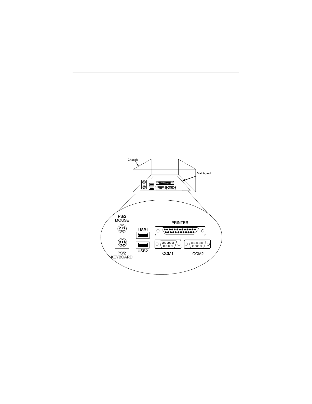
Highly Convenient Integrated I/O Connectors
This mainboard features has an integrated rear I/O panel that incorporates a full
set of I/O ports to allow simple and convenient connections to a complete
selection of external peripheral devices.
In addition to two 16550A UART compatible serial ports and one EPP/ECP
capable parallel port, the panel features two USB connectors that provide high
speed connections to the new generation of USB peripheral devices. PS/2
keyboard and PS/2 mouse connectors provide additional I/O connectivity.

PA-2011 Mainboard Manual
10
This Page Intetnionally Left Blank

11
Installation Procedures
The PA-2011 has several user-adjustable jumpers on the board that allow you to
configure your system to suit your requirements. This chapter contains
information on the various jumper settings on your mainboard.
To set up your computer, you should follow these installation steps:
■Step 1 -
Set system jumpers
■Step 2 -
Install System RAM modules
■Step 3 -
Install the CPU
■Step 4 -
Install expansion cards
■Step 5 -
Connect cables and power supply
■Step 6 -
Set up BIOS feature (Please read Chapter Three.)
Chapter 2
PA-2011 Mainboard Manual
12
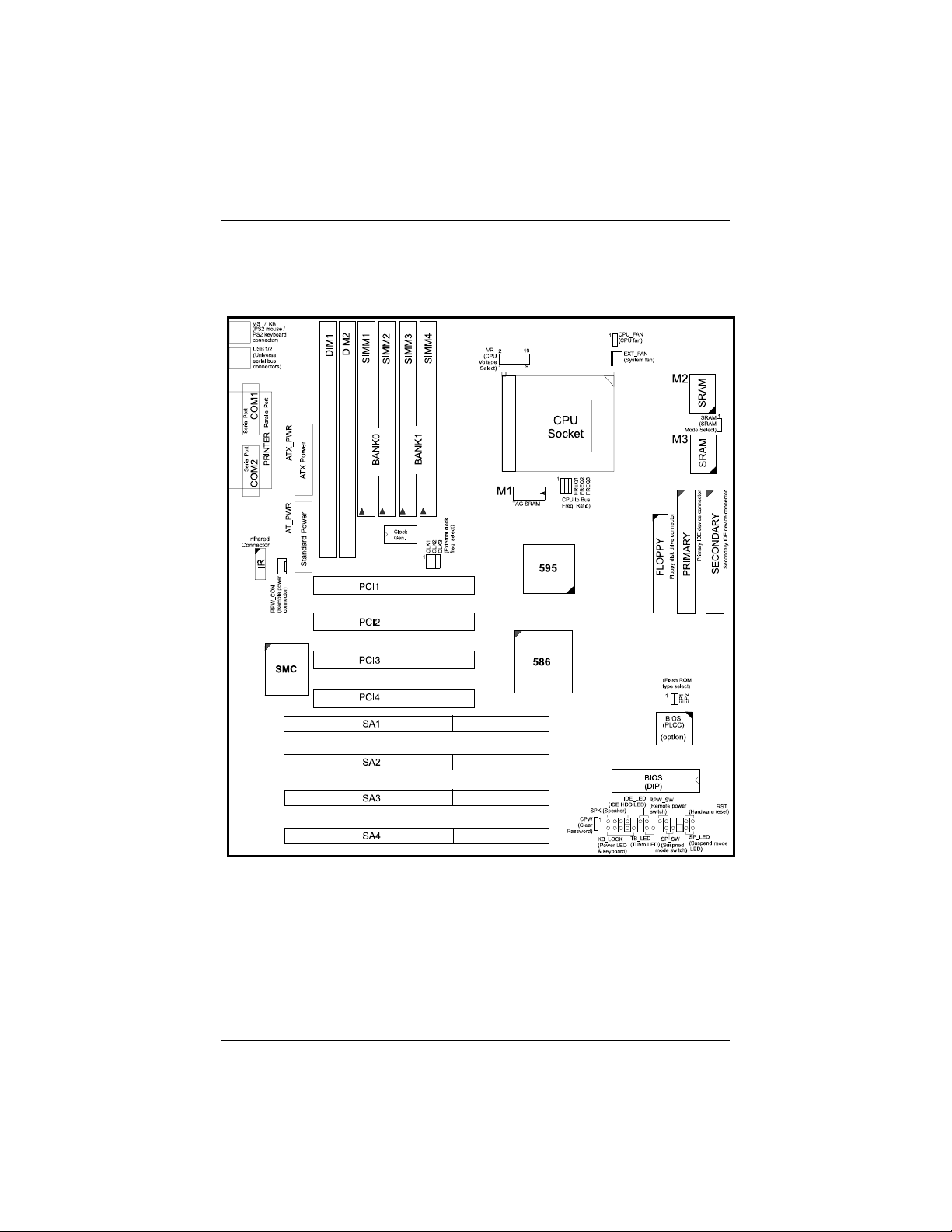
Mainboard Layout

Installation Procedures
13
1). Set System Jumpers
Jumpers
Jumpers are used to select the operation modes for your system. Some jumpers
on the board have three metal pins with each pin representing a different
function. To set a jumper, a black cap containing metal contacts is placed over
the jumper pins according to the required configuration. A jumper is said to be
shorted when the black cap has been placed on one or two of its pins. The types
of jumpers used in this manual are shown below:
NOTE : Users are not encouraged to change the jumper settings not listed in
this manual. Changing the jumper settings improperly may adversely affect
system performance.

PA-2011 Mainboard Manual
14
Clear Password: CPW
This jumper allows you to set the password configuration to Enabled or
Disabled. You may need to enable this jumper if you forget your password.
Flash EPROM Type Selection: EP1, EP2
These two jumpers allow you to configure the Flash EPROM chip
Table of contents
Other FIC Motherboard manuals


Popular Motherboard manuals by other brands


Asus
Asus M3A78 - Motherboard - ATX owner's manual

Acroname
Acroname BrainStem/MTM Getting started

Texas Instruments
Texas Instruments LM74670-SQEVM user guide

Texas Instruments
Texas Instruments INA210-215EVM user guide

Asus
Asus A7N8X-E Deluxe quick start guide

VIA Technologies
VIA Technologies 10GWG21Q00020 user manual