Fieldpiece HVAC Guide HG1 User manual

2
WWW.FIELDPIECE.COM WWW.FIELDPIECE.COM WWW.FIELDPIECE.COM WWW.FIELDPIECE.COM WWW.FIELDPIECE.COM WWW.F
I
I
ELDPIECE.COM WWW.FIELDPIECE.COM WWW.FIELDPIECE.COM WWW.FIELDPIECE.COM WWW.FIELDPIECE.COM WWW.FIELDPIECE.C
O
HVAC GUIDETM Tester
Field Manual
HG1 & HG2
Do it right the rst time!
Minimize call-backs. Reduce testing and diagno-
sis time. Improve the technician’s technical capability.
Minimize reliance on outside technical help. e HVAC
GuideTM Guided Probe Tester can do all that and more.
e display leads the technician step by step through
the most common HVAC tests. It then makes a diagno-
sis and recommends action. e HVAC GuideTM tester
makes the service call or installation faster, easier, clean-
er, and more complete.
Improper refrigerant charge is one of the primary
reasons for call-backs. It can cause compressor noise,
shorten compressor life, and lower capacity. Using the
built-in Superheat and Subcooling tests, the HVAC
GuideTM tester leads the technician through a step by
step procedure to determine if the refrigerant charge
is correct. With the proper accessory heads, no calcula-
tions, charts, or data entry are needed.
Improper airow can cause customers to complain
that they are too hot or too cold. Once you’ve checked
the duct system for restrictions and leaks, adjust the air-
ow with the Target Evaporator Exit Temperature pro-
cedure that’s built into the HVAC GuideTM tester.
An improperly adjusted furnace or water heater will
cause your customers to call you and complain about
the temperature being too cold or the hot water not be-
ing hot enough. Use the Combustion test built into the
HVAC GuideTM tester to determine if you have the right
air/fuel mixture by analyzing the combustion products.
You can then make adjustments to make sure the equip-
ment works as it should.
e CheckMe!® test (model HG2 only) is a much
more sophisticated air conditioner test procedure that
will help diagnose more complex problems by looking
at the air conditioning system as a whole.
Do it right the rst time, do it faster, do it easier, do
it more completely and avoid call-backs in the process.
Table of Contents
Do it Right the First Time! . . . . . . . . . . . . . . . . . . . . . . . . . . . . . . 2
Table of Contents. . . . . . . . . . . . . . . . . . . . . . . . . . . . . . . . . . . . . . 3
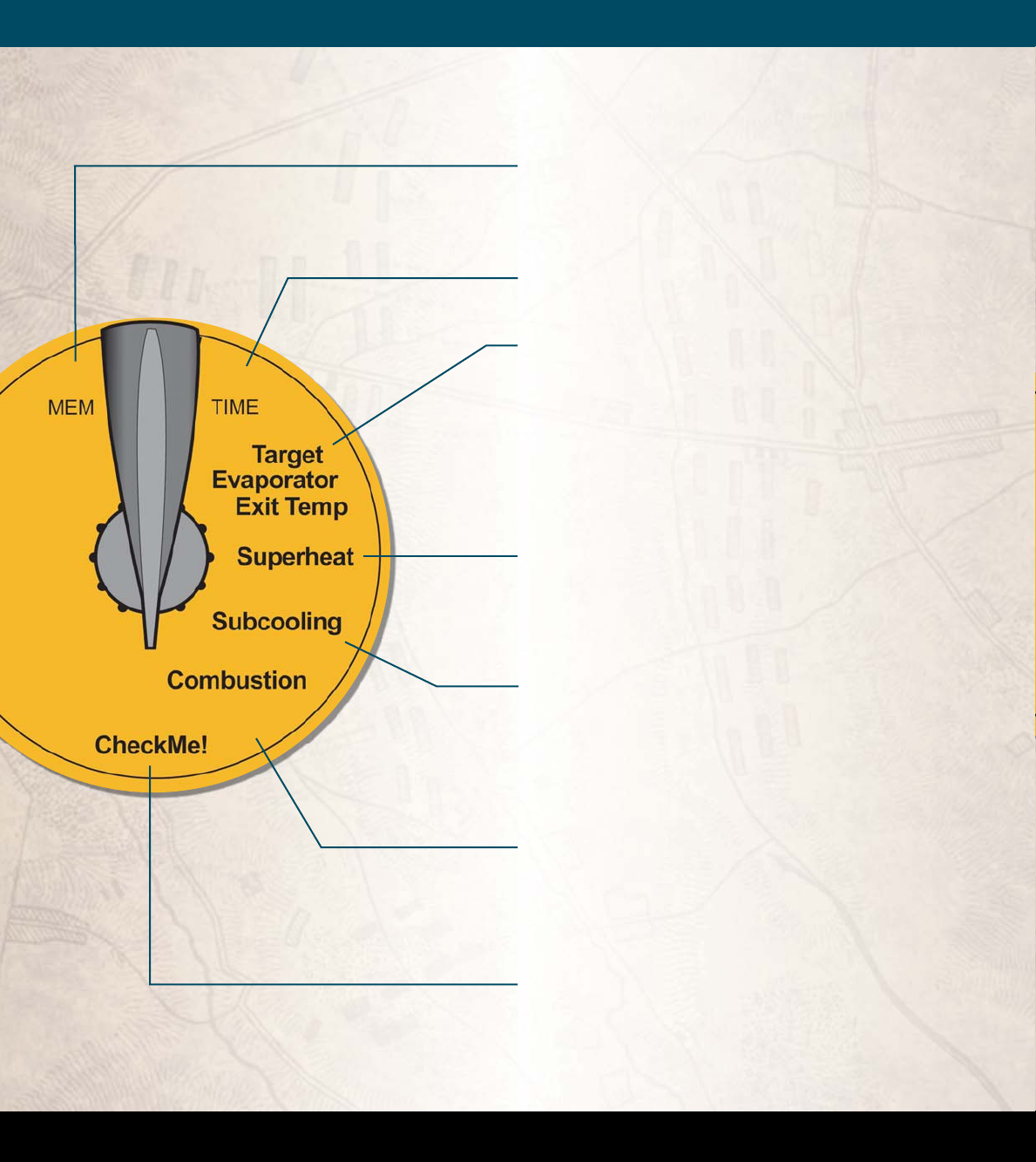
HVAC GuideTM Tester Controls . . . . . . . . . . . . . . . . . . . . . . . . . . 4
Select the Test (Switch Positions) . . . . . . . . . . . . . . . . . . . . . . . 6
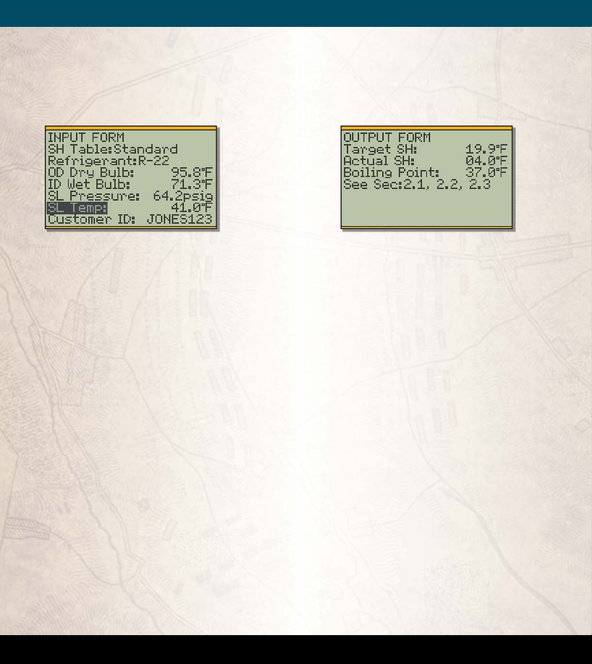
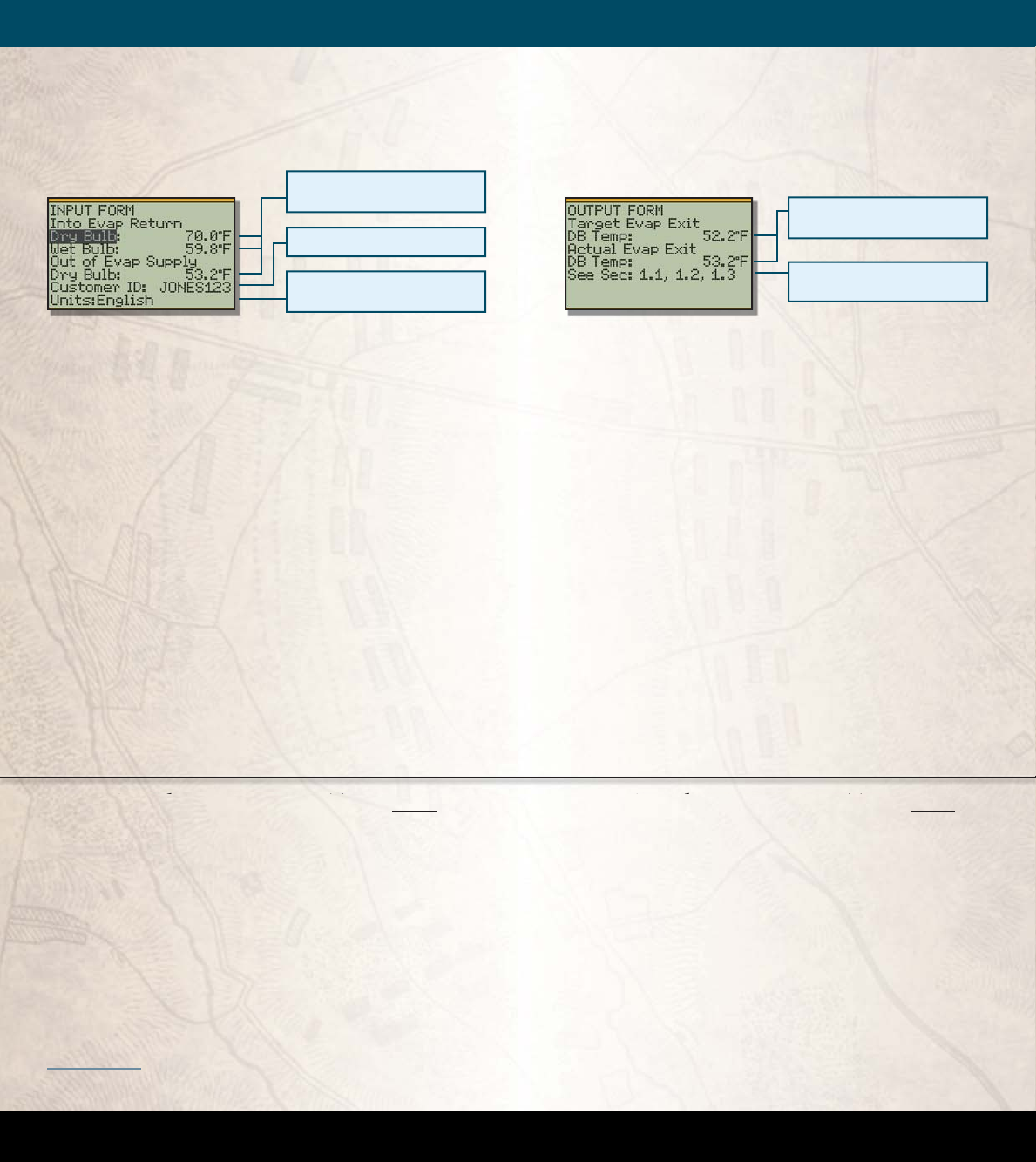
Fill in the INPUT FORM . . . . . . . . . . . . . . . . . . . . . . . . . . . . . . . . . 8
Read the OUTPUT FORM . . . . . . . . . . . . . . . . . . . . . . . . . . . . . . . 9
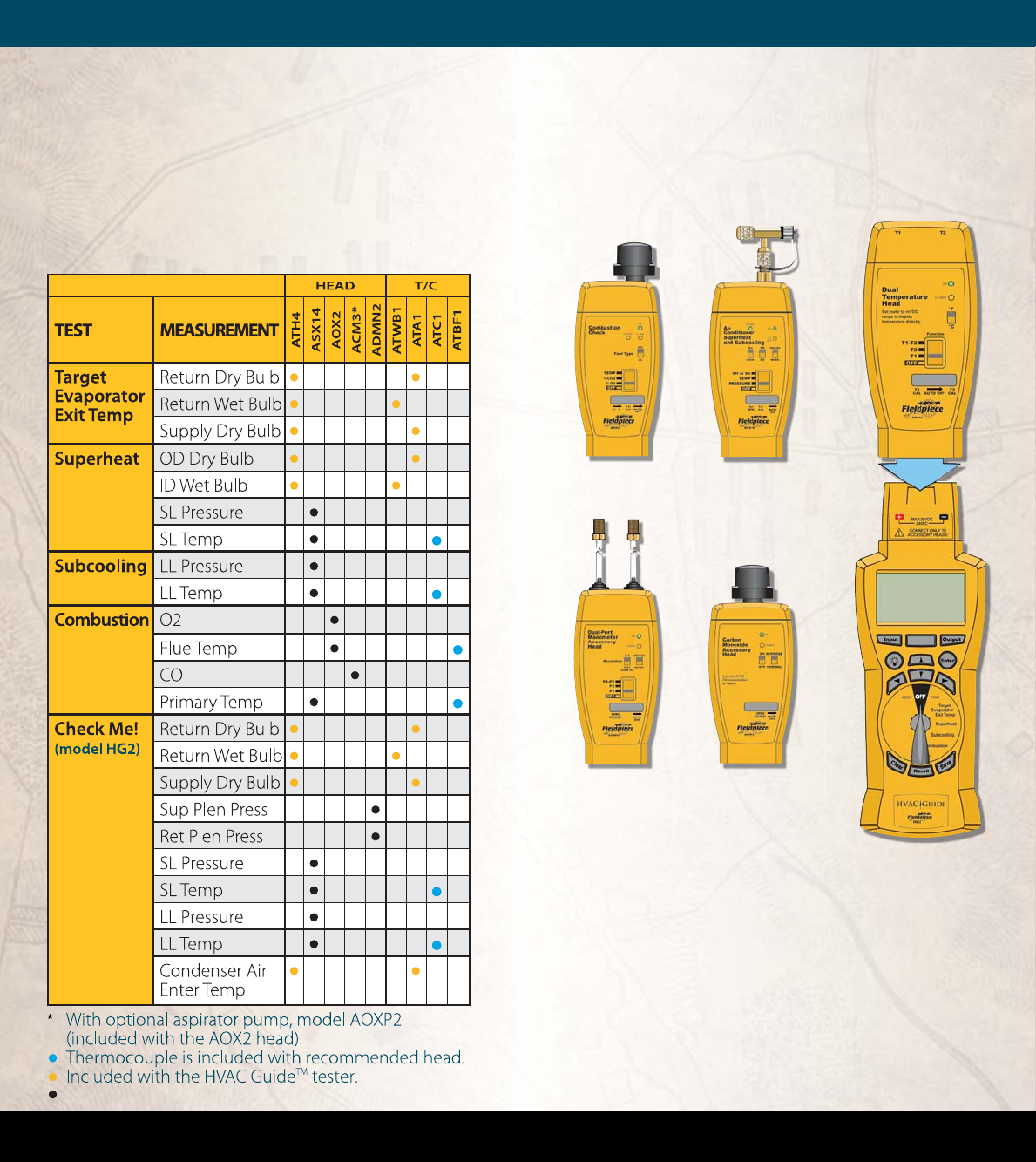
What Accessory Heads Do I Need? . . . . . . . . . . . . . . . . . . . . 10
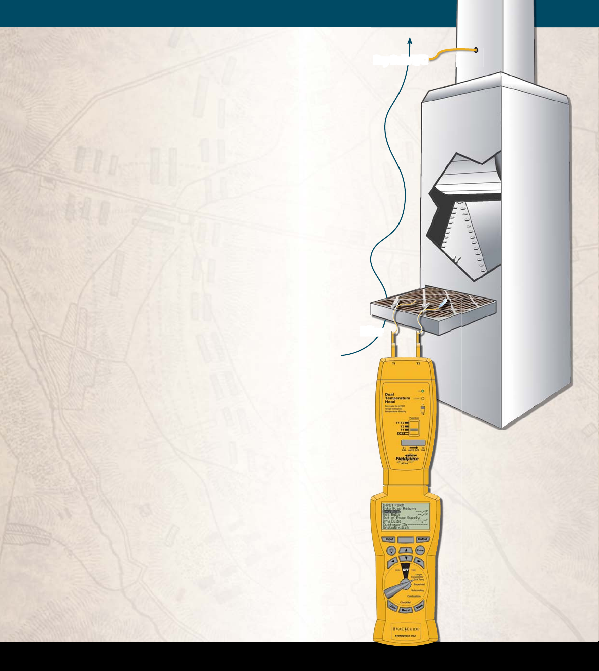
How to Connect an Accessory Head . . . . . . . . . . . . . . . . . . . 11
Tests . . . . . . . . . . . . . . . . . . . . . . . . . . . . . . . . . . . . . . . . . . . . . . . . . 12
Target Evaporator Exit Temperature . . . . . . . . . . . . . . . . . 12
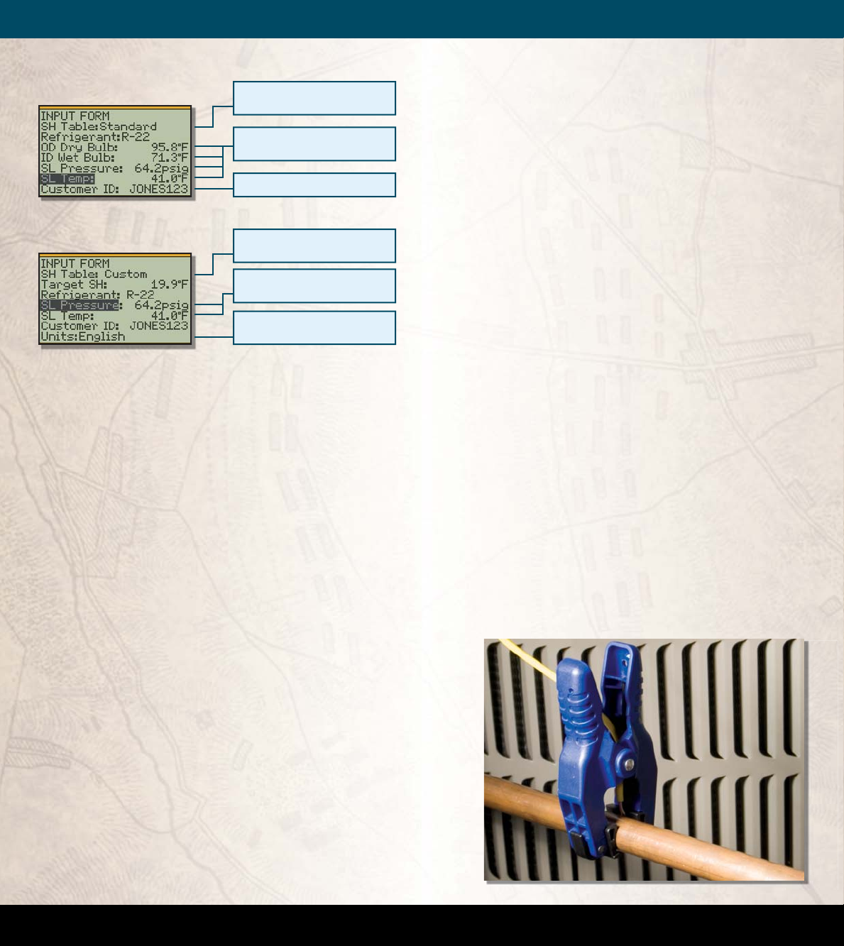
Superheat. . . . . . . . . . . . . . . . . . . . . . . . . . . . . . . . . . . . . . . . . . 16
Superheat and Subcooling FAQ part 1 . . . . . . . . . . . . 21
Subcooling. . . . . . . . . . . . . . . . . . . . . . . . . . . . . . . . . . . . . . . . . 22
Superheat and Subcooling FAQ part 2 . . . . . . . . . . . . 27
Combustion. . . . . . . . . . . . . . . . . . . . . . . . . . . . . . . . . . . . . . . . 28
“CheckMe!®” . . . . . . . . . . . . . . . . . . . . . . . . . . . . . . . . . . . . . . . 34
Advanced Operations . . . . . . . . . . . . . . . . . . . . . . . . . . . . . . . . 50
Time . . . . . . . . . . . . . . . . . . . . . . . . . . . . . . . . . . . . . . . . . . . . . . . 50
Memory (MEM). . . . . . . . . . . . . . . . . . . . . . . . . . . . . . . . . . . . . 50
Units. . . . . . . . . . . . . . . . . . . . . . . . . . . . . . . . . . . . . . . . . . . . . . . 51
Customer ID. . . . . . . . . . . . . . . . . . . . . . . . . . . . . . . . . . . . . . . . 51
Clearing a single input or INPUT FORM . . . . . . . . . . . . . . 52
Saving Data . . . . . . . . . . . . . . . . . . . . . . . . . . . . . . . . . . . . . . . . 52
Recalling Saved Tests . . . . . . . . . . . . . . . . . . . . . . . . . . . . . . . 53
Contrast Adjustment . . . . . . . . . . . . . . . . . . . . . . . . . . . . . . . 53
PC Software . . . . . . . . . . . . . . . . . . . . . . . . . . . . . . . . . . . . . . . . . . 54
Installing the PC Software . . . . . . . . . . . . . . . . . . . . . . . . . . 54
Communicating with a PC . . . . . . . . . . . . . . . . . . . . . . . . . . 55
Transfer Tests from the HVAC GuideTM Tester to a PC. . 56
Transfer Tests From the PC to the HVAC GuideTM Tester. . 58
Looking at Downloaded Data. . . . . . . . . . . . . . . . . . . . . . . 60
Other Operations with PC Software . . . . . . . . . . . . . . . . . . . 61
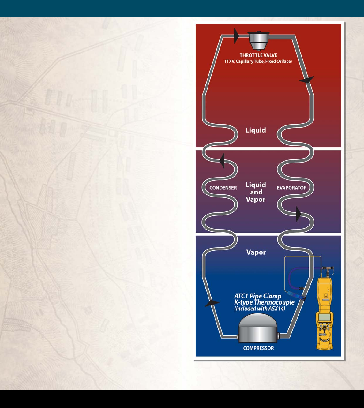
Air Conditioning Basics . . . . . . . . . . . . . . . . . . . . . . . . . . . . . . . 64
Combustion Basics . . . . . . . . . . . . . . . . . . . . . . . . . . . . . . . . . . . 66
Product Specications . . . . . . . . . . . . . . . . . . . . . . . . . . . . . . . . 68
Limited Warranty . . . . . . . . . . . . . . . . . . . . . . . . . . . . . . . . . . . . . 69
Obtaining Service . . . . . . . . . . . . . . . . . . . . . . . . . . . . . . . . . . . . 70
Disclaimer. . . . . . . . . . . . . . . . . . . . . . . . . . . . . . . . . . . . . . . . . . . . 70
John Proctor and Title 24 . . . . . . . . . . . . . . . . . . . . . . . . . . . . . 71
© Copyright Fieldpiece Instruments 2007

4
WWW.FIELDPIECE.COM WWW.FIELDPIECE.COM WWW.FIELDPIECE.COM WWW.FIELDPIECE.COM WWW.FIELDPIECE.COM WWW.F
I
I
ELDPIECE.COM WWW.FIELDPIECE.COM WWW.FIELDPIECE.COM WWW.FIELDPIECE.COM WWW.FIELDPIECE.COM WWW.FIELDPIECE.C
O
Top View
HVAC GUIDETM Tester Controls
Bottom View
Makes a selection or enters
data.
Enter Button
PC cable plugs into the
bottom to transfer data.
PC Cable Interface
Returns you to the INPUT
FORM.
Input Button
Connect accessory heads
here.
Input Jacks
Turns on the backlight for
30 sec.
Backlight Button
Displays INPUT FORMS and
OUTPUT FORMS.
Dot Matrix LCD Display
Navigate within FORMS
and screens.
Arrow Buttons
Rotate to select test.
Switch Position Dial
After "POWER OFF" clears,
unscrew the two screws to
replace the 6AA batteries.
Battery Cover
Recalls previous tests within
each switch position. Previous
tests can only be accessed
through the switch position in
which they were performed
and are sorted by Customer ID
and Time Stamp.
Recall Button
Saves the current INPUT FORM.
Inputs are saved with Customer
ID and Time Stamp. See Saving
Data section for details.
Save Button
Triggers calculations and takes
you to the OUTPUT FORM.
Output Button
Clears a single input or
the entire INPUT FORM by
holding for 3 seconds.
Clear Button
Test Equipment Depot - 800.517.8431 - 99 Washington Street Melrose, MA 02176
TestEquipmentDepot.com

6
WWW.FIELDPIECE.COM WWW.FIELDPIECE.COM WWW.FIELDPIECE.COM WWW.FIELDPIECE.COM WWW.FIELDPIECE.COM WWW.F
I
I
ELDPIECE.COM WWW.FIELDPIECE.COM WWW.FIELDPIECE.COM WWW.FIELDPIECE.COM WWW.FIELDPIECE.COM WWW.FIELDPIECE.C
O
Select the Test Switch Positions
MEM: Erase a single test, an entire customer’s set of
tests, or all data. MEM also allows you to check
memory status, rmware version, and communi-
cate with a PC for data transfer.
TIME: Set current time and date for internal clock. All
tests are time stamped and cannot be changed later.
Target Evaporator Exit Temperature: By mea-
suring the return wet bulb and dry bulb, the HVAC
GuideTM tester calculates a target evaporator exit
temperature. To ensure that the A/C system has the
proper airow per tonnage, the actual evaporator
exit temperature must be within ±3°F of the target
evaporator exit temperature as outlined in CA title
24.
Superheat: For a xed restrictor air conditioning sys-
tem, the HVAC GuideTM tester uses the indoor wet
bulb and outside dry bulb to calculate a target su-
perheat and uses the suction line temperature and
pressure to calculate actual superheat.
Subcooling: For a TXV/EXV air conditioning system,
the HVAC GuideTM tester uses liquid line tempera-
ture and pressure to calculate actual subcooling. If
the manufacture’s target subcooling is not available,
the HVAC GuideTM tester provides a conservative
estimate.
Combustion: For combustion equipment, the HVAC
GuideTM tester uses %O2, ue temperature, primary
temperature and CO ppm to calculate %CO2, % Ex-
cess Air, CO (air free), Net Temperature, Standard
Eciency and Siegert Eciency.
CheckMe!® (model HG2): is is a more advanced
test for determining the overall state of an air con-
ditioning system. e CheckMe!® test will give you a
diagnosis of the system in plain English and a list of
potential problems in the system.

8
WWW.FIELDPIECE.COM WWW.FIELDPIECE.COM WWW.FIELDPIECE.COM WWW.FIELDPIECE.COM WWW.FIELDPIECE.COM WWW.F
I
I
ELDPIECE.COM WWW.FIELDPIECE.COM WWW.FIELDPIECE.COM WWW.FIELDPIECE.COM WWW.FIELDPIECE.COM WWW.FIELDPIECE.C
O
Fill in the INPUT FORM
Figure 1. INPUT FORM for the Superheat test.
e INPUT FORM lists parameters in the order of
expected entry.
ree ways to enter data:
1. Automatic: Attach appropriate head, select ap-
propriate line with the UP/DOWN arrows, press
ENTER to start measuring, and press ENTER
again to lock in the value.
2. Drop down menu: To change a parameter that
has a default, press RIGHT arrow or ENTER, use
UP/DOWN arrows to scroll through the drop-
down list, and press ENTER again.
3. Manual: Enter system data (or to enter test data
not taken with an accessory head) by pressing the
RIGHT arrow and then, character-by-character, use
the UP/DOWN arrows and the RIGHT arrow to
‘type in’ the value. When nished press ENTER. Tar-
get Evaporator Exit Temperature test has no system
data to enter.
Read the OUTPUT FORM
Figure 2. OUTPUT FORM for the Superheat test.
To display the OUTPUT FORM, ll in the INPUT
FORM correctly and press the OUTPUT button or
scroll down. If the INPUT FORM is missing inputs, the
appropriate lines on the OUTPUT FORM will be blank.
If the data entered on the INPUT FORM is out of range
or physically impossible, an error message is displayed.
e OUTPUT FORM displays the results of the calcula-
tions.
• e “See Sec:” at the bottom of the OUTPUT FORM
tells you what section in the manual has more infor-
mation about how to perform the specic test and
what the results mean.
• To ensure that your changes have optimized the sys-
tem, retest aer the system is stabilized.
e CheckMe!® test (model HG2) has a more de-
tailed OUTPUT FORM. If everything on the INPUT
FORM is lled out properly, the CheckMe!® OUTPUT
FORM will rank the possible problems in order of likeli-
hood and describe how to x them. If you haven’t taken
all the necessary measurements, the rst line will tell
you what you need to do for a complete diagnosis.

10
WWW.FIELDPIECE.COM WWW.FIELDPIECE.COM WWW.FIELDPIECE.COM WWW.FIELDPIECE.COM WWW.FIELDPIECE.COM WWW.F
I
I
ELDPIECE.COM WWW.FIELDPIECE.COM WWW.FIELDPIECE.COM WWW.FIELDPIECE.COM WWW.FIELDPIECE.COM WWW.FIELDPIECE.C
O
What Accessory Heads
Do I Need?
Refer to the chart below to nd the recommend-
ed accessory head and thermocouple for each mea-
surement. Automatically input measurements with
Fieldpiece accessory heads for maximum accuracy, or
manually input from non-Fieldpiece test equipment.
How to Connect an
Accessory Head
ATH4 on
HVAC Guide TM tester
AOX2
ACM3
ADMN2
ASX14
Recommended accessory head.
Test Equipment Depot - 800.517.8431 - 99 Washington Street Melrose, MA 02176
TestEquipmentDepot.com

12
WWW.FIELDPIECE.COM WWW.FIELDPIECE.COM WWW.FIELDPIECE.COM WWW.FIELDPIECE.COM WWW.FIELDPIECE.COM WWW.F
I
I
ELDPIECE.COM WWW.FIELDPIECE.COM WWW.FIELDPIECE.COM WWW.FIELDPIECE.COM WWW.FIELDPIECE.COM WWW.FIELDPIECE.C
O
Tests
1.1 Target Evaporator Exit Temperature
For given return plenum air conditions, Target
Evaporator Exit Temperature gives you an indication of
the proper indoor airow. is test can be easily per-
formed simultaneously with superheat or subcooling
tests.
If actual evaporator exit temperature is more than
3°F above or below the Target Evaporator Exit Tempera-
ture, an airow problem may exist. Ensure that lters are
clear, dampers are adjusted properly and the fan speed
is set correctly if it can be varied. e Target Evapora-
tor Exit Temperature switch position uses the table from
California Title 24.
Direction
of Airow
A-Coil
A-Coil
Filter
Fan
Fan
Dry Bulb and
Dry Bulb and
Wet Bulb T/C
Wet Bulb T/C
Dry Bulb T/C
Supply Plenum
Supply Plenum
C
WWW.FIELDPIECE.CO WWW.
FI
t
CE
E
E
E
E
E
E
E
E
E
E
E
E
E
.
.COM
WWW
.
FIELDPIECE
.
C
O
M
M
M
M
M
M
M
M
M
M
M
M
M
M
M
W
W
t
er
Figure 3. Setting up the ATH4 and
HVAC GuideTM tester to measure dry
bulb and wet bulb temperatures
between filter and coil.

14
WWW.FIELDPIECE.COM WWW.FIELDPIECE.COM WWW.FIELDPIECE.COM WWW.FIELDPIECE.COM WWW.FIELDPIECE.COM WWW.F
I
I
ELDPIECE.COM WWW.FIELDPIECE.COM WWW.FIELDPIECE.COM WWW.FIELDPIECE.COM WWW.FIELDPIECE.COM WWW.FIELDPIECE.C
O
1.3 Target Evaporator Exit Temperature
OUTPUT FORM
Figure 5. OUTPUT FORM for Target Evaporator ExitTemperature.
Press OUTPUT for the Target Evaporator Exit Tem-
perature OUTPUT FORM.
Target Evap Exit DB Temp (Target Evaporator
Exit Dry Bulb Temperature): is is the target exit
temperature based on the measured indoor condi-
tions.
Actual Evap Exit DB Temp (Actual Evaporator
Exit Dry Bulb Temperature): is is the measured
temperature of the air in the supply.
e Actual Evap Exit DB Temp should be
within ±3°F of the Target Evap Exit DB Temp. If
the temperature is outside of this range, the technician
should make modications to correct the problem.
1.2 Target Evaporator Exit Temperature
INPUT FORM
Figure 4. INPUT FORM for Target Evaporator ExitTemperature.
Into Evap Return Dry Bulb and Wet Bulb: Take
measurements as close to the inlet of the air handler
as possible. If the lter is just before the air handler,
the easiest way is to clip an ATWB1 and ATA1 to the
lter on the side facing the evaporator and take the
measurements. If the lter is not before the evapo-
rator, make small holes in the return plenum just big
enough for the probes. Seal any holes before leaving
the jobsite.
Out of Evap Supply DB (dry bulb temp leaving
the evaporator): Measure in the center of the supply
plenum. Punch a small hole in the supply plenum
and insert a calibrated dry bulb thermocouple such
as the ATA1 or ATB1. Make sure the thermocouple
is in the center of the plenum cross-section. Seal the
hole when nished.
Can be measured automatically with
Fieldpiece accessory heads.
Units can be changed to either English
or Metric.
Customer ID is useful for record keeping.
Sections of manual with more
information about this test.
If Target and Actual are more than 3°F
apart a modification is needed.
An Actual Evap Exit DB Temp above the
Target Evap Exit DB Temp usually indicates low
capacity. Occasionally airow is higher than expected.
Look for causes of low capacity such as refrigerant mis-
charge or dirty condenser coil. If the airow is high,
correct by lowering the fan speed.
Because everything within the system is inter-de-
pendent, one adjustment can aect other parts of the
system. For example, increasing airow increases the
superheat, which may require adding refrigerant. Aer
modications, allow 15 minutes to stabilize and then
retest.
An Actual Evap Exit DB Temp below the
Target Evap Exit DB Temp indicates low airow.
Increasing airow can be accomplished by elimi-
nating restrictions in the duct system, increasing blower
speed, cleaning lters or opening registers. Aer cor-
rective measures are taken, repeat measurement proce-
dures as oen as necessary to establish adequate airow
range. Allow system to stabilize for 15 minutes before
repeating measurement procedure.1
1 2005 Residential ACM Manual, Page RD-5, (#5-7)
Al T
Al T

16
WWW.FIELDPIECE.COM WWW.FIELDPIECE.COM WWW.FIELDPIECE.COM WWW.FIELDPIECE.COM WWW.FIELDPIECE.COM WWW.F
I
I
ELDPIECE.COM WWW.FIELDPIECE.COM WWW.FIELDPIECE.COM WWW.FIELDPIECE.COM WWW.FIELDPIECE.COM WWW.FIELDPIECE.C
O
2.1 Superheat
Superheat is the temperature rise above the boiling
point of the refrigerant aer the evaporator. Too high,
and the refrigerant boils o early in the evaporator and
‘wastes’ most of the capacity of the evaporator. Too low,
and you risk liquid going into the compressor.
Using superheat is the best way to obtain proper
refrigerant charge for a xed restrictor metering device
system.
If the air conditioner is in good working order and
the airow is adjusted properly, comparing the actual
and target superheat will tell you if refrigerant needs to
be added or recovered. Ensure the pressure never ex-
ceeds the manufacturer's maximum overload pressure
guidelines.
On a xed restrictor system, the target superheat is
determined based upon the indoor wet bulb and out-
door dry bulb temperatures. Proper superheat ensures
the compressor doesn't ood under a low indoor load
and that the maximum eciency and capacity are main-
tained.
Figure 6. Using the ASX14 Superheat/Subcooling Head to gather suction line
temperature and pressure for the HVAC GuideTM tester SuperheatTest.
Test Equipment Depot - 800.517.8431 - 99 Washington Street Melrose, MA 02176
TestEquipmentDepot.com

18
WWW.FIELDPIECE.COM WWW.FIELDPIECE.COM WWW.FIELDPIECE.COM WWW.FIELDPIECE.COM WWW.FIELDPIECE.COM WWW.F
I
I
ELDPIECE.COM WWW.FIELDPIECE.COM WWW.FIELDPIECE.COM WWW.FIELDPIECE.COM WWW.FIELDPIECE.COM WWW.FIELDPIECE.C
O
2.2 Superheat INPUT FORM
Figure 7. INPUT FORM for StandardTable SuperheatTest.
Figure 8. INPUT FORM for CustomTable SuperheatTest.
SH Table: Default: “Standard” uses the target super-
heat table from Title 24 for xed restrictor systems.
Other selection: “Custom” allows you to enter your
own target superheat by displaying the Target SH
input.
Target SH (Custom SH Table): Change the SH Ta-
ble to Custom and enter the manufacturer’s recom-
mended superheat in the Target SH input.
Refrigerant: Default: R-22. Other selections: R-410A,
R-134A, R-404A, R-407C, R-409A, R-408A, R-507A,
R-414B (HotshotTM), R-422C (OneshotTM), R-422B
(NU222BTM) or R-12.
OD Dry Bulb (outdoor dry bulb, Standard SH Ta-
ble): Clip a calibrated ATA1 to the inlet of the con-
denser ns (typically on the side of the condenser),
in the shade if possible. Note that the temperature of
the air entering the outdoor coil can be considerably
dierent than the ambient temperature due to recir-
culation of air exiting the unit. Determine the aver-
age temperature of the air entering the condenser.
ID Wet Bulb (indoor wet bulb, Standard SH Table):
Take measurements very close or within the return
air side of the inlet to the air handler (not at the re-
turn grill since temperatures change by the time the
air reaches the indoor coil). Wet the wet bulb sensor
(ATWB1) and insert it aer 15 minutes of continu-
ous running. Clip downstream of the lter if the
lter is just before the air handler. Clip on the side
facing the evaporator and take the measurements.
If the lter is not before the evaporator, make small
holes in the return plenum just big enough for the
probes. Seal any holes before leaving the jobsite.
Watch the wet bulb temperature; it will drop and
then stabilize. e wet bulb temperature is the sta-
bilized reading. If the sensor starts to dry out, the
reading will rise and the wrong temperature will be
recorded.
SL Pressure (suction line pressure): Connect the
ASX14 to the suction side service port. Select pres-
sure mode on the ASX14 head. e system must be
stabilized before taking the measurements. Enter
data manually if you want to get pressure from your
gauges. e analysis is only as good as the measure-
ments. e Fieldpiece ASX14 has better resolution
than most gauge sets.
SL Temp (suction line temperature): Measure near SL
service port (within 6 inches). Use the ATC1, ATC2
or ATC3 to get a good pipe temperature. e clamp
should be perpendicular to the pipe and should be
securely seated with the sensor in contact with the
suction line. If working on a package unit make sure
you are at least 6 inches away from the compressor.
Figure 9. ATC1 pipe clamp thermocouple attached to a pipe correctly.
Fi 9 ATC1 i l th l tt h d t i tl
Standard table uses the Title 24 target
superheat table.
Customer ID is useful for record keeping.
Can be measured automatically with
Fieldpiece accessory heads.
Custom table allows you to enter your
own target superheat value.
Can be measured automatically with
Fieldpiece accessory heads.
Units can be changed to either English
or Metric.

20
WWW.FIELDPIECE.COM WWW.FIELDPIECE.COM WWW.FIELDPIECE.COM WWW.FIELDPIECE.COM WWW.FIELDPIECE.COM WWW.F
I
I
ELDPIECE.COM WWW.FIELDPIECE.COM WWW.FIELDPIECE.COM WWW.FIELDPIECE.COM WWW.FIELDPIECE.COM WWW.FIELDPIECE.C
O
2.3 Superheat OUTPUT FORM
Figure 10. Superheat Test OUTPUT FORM.
Press OUTPUT for the Superheat OUTPUT FORM.
Target SH (Superheat): Indicates what the superheat
should be as calculated from outdoor dry bulb and
indoor wet bulb
Actual SH (Superheat): Shows the superheat calculated
from the measured suction line temperature and suc-
tion line pressure.
Boiling Point: is is the saturation temperature of the
refrigerant in the evaporator coil. It is one of the tem-
peratures from which superheat is calculated.
e
Actual SH (superheat) should be within ±5°F of
the Target SH to ensure optimum performance. If the ac-
tual SH is outside this range, modications to the charge
or adjustments to the restrictor (TXV) are necessary.
Adding refrigerant lowers your Actual SH. Recover-
ing refrigerant increases your Actual SH. e amount of
refrigerant necessary to add or recover will vary based on
the size of the system and the dierence between the Ac-
tual and Target SH.
Because everything within the system is inter-depen-
dent, one adjustment can aect other parts of the system.
For example, increasing airow increases the superheat,
which may require adding refrigerant. Aer modica-
tions, allow 15 minutes to stabilize and then retest.
Superheat and Subcooling FAQ
Q: How do superheat/subcooling tools work?
A: Superheat tools measure suction line pressure and
suction line temperature, and calculate the actual su-
perheat. Subcooling tools measure the liquid line pres-
sure and liquid line temperature and calculate actual
subcooling. e refrigerant charts for calculations are
incorporated into the soware of the HVAC GuideTM
tester.
Q: When should I take my actual and target
superheat/subcooling?
A: Superheat and subcooling readings must be taken
when the system is in a steady state. Typically a resi-
dential system will be in a steady state aer 10-15 min-
utes. Turn the system on and set the thermostat low to
ensure that the system doesn’t turn o during your
testing. Once the system’s temperatures and pressures
are not uctuating, the system is in a steady state.
Wet bulb temperature, outdoor dry bulb, suction line
pressure and suction line temperature must be taken
within a short time period to ensure valid results.
Conditions that aect your target superheat and tar-
get subcooling can change by the minute.
Q: What do I do with my ACTUAL superheat
or ACTUAL subcooling measurements?
A: Compare actual readings against the target superheat/
subcooling. As a general rule, if superheat is too high,
add refrigerant. If too low, remove refrigerant. If sub-
cooling is too low, remove refrigerant. If subcooling is
too high, add refrigerant. Consult the manufacturer’s
specications before adding or recovering refrigerant
as further diagnostic tests may be needed
Continued on page 27
Sections of manual with more information
about this test.
If Target SH and Actual SH are more than
5°F apart, as in this example, you need to
make adjustments to the system.
Boiling point is used to calculate Superheat.

22
WWW.FIELDPIECE.COM WWW.FIELDPIECE.COM WWW.FIELDPIECE.COM WWW.FIELDPIECE.COM WWW.FIELDPIECE.COM WWW.F
I
I
ELDPIECE.COM WWW.FIELDPIECE.COM WWW.FIELDPIECE.COM WWW.FIELDPIECE.COM WWW.FIELDPIECE.COM WWW.FIELDPIECE.C
O
3.1 Subcooling
Subcooling is the temperature decrease below the
boiling point (same as the condensing point) in the con-
denser. Too high, and refrigerant condenses too early in
the condenser and ‘wastes’ most of the capacity of the
condenser. Too low, and a mixture of gas and liquid can
be delivered to the expansion valve, reducing eciency.
Subcooling is the best way to obtain proper refriger-
ant charge for a TXV/EXV system.
If the air conditioner is in good working order and
the airow is adjusted properly, comparing the actual
and target subcooling will tell you if refrigerant needs
to be added or recovered (ensure the pressure never ex-
ceeds the manufacturer's maximum overload pressure
guidelines).
In a properly working TXV/EXV system, the super-
heat is held constant. Ensure the TXV/EXV bulb is in-
stalled properly, there is proper refrigerant to obtain tar-
get subcooling, and there are no liquid line restrictions.
Adjust refrigerant charge so that the actual subcooling is
within ±3°F of target subcooling.
Figure 11. Using the ASX14 Superheat/Subcooling Head to gather liquid line
temperature and pressure for the HVAC GuideTM tester SubcoolingTest.
Test Equipment Depot - 800.517.8431 - 99 Washington Street Melrose, MA 02176
TestEquipmentDepot.com

24
WWW.FIELDPIECE.COM WWW.FIELDPIECE.COM WWW.FIELDPIECE.COM WWW.FIELDPIECE.COM WWW.FIELDPIECE.COM WWW.F
I
I
ELDPIECE.COM WWW.FIELDPIECE.COM WWW.FIELDPIECE.COM WWW.FIELDPIECE.COM WWW.FIELDPIECE.COM WWW.FIELDPIECE.C
O
3.2 Subcooling INPUT FORM
Figure 12. Subcooling Test INPUT FORM question.
Figure 13. Subcooling Test INPUT FORM with Manufacturer's Data.
Figure 14. Subcooling Test INPUT FORM without Manufacturer's Data.
Does the manufacturer have a recommended
subcooling? Default: Yes. Always answer "YES" if
you have a manufacturer’s recommended subcooling.
Other selection: "NO" will use a conservative estimate
for Target SC (Subcooling).
Refrigerant: Default: R-22. Other selections: R410A,
R-134A, R-404A, R-407C, R-409A, R-408A, R-507A,
R-414B (HotshotTM), R-422C (OneshotTM), R-422B
(NU222BTM) or R-12.
Target SC (WITH Manufacturer’s Data): Man-
ually input the manufacturer’s target subcooling.
LL Pressure (liquid line pressure): Connect the
ASX14 to the liquid line service port. Set the acces-
sory head to measure pressure and ensure the read-
ing stabilizes before locking in the reading. Enter
data manually if you want to get pressure from your
gauges. e analysis is only as good as the measure-
ments. e Fieldpiece ASX14 has better resolution
than most gauge sets.
LL Temp (liquid line temperature): Measure near the
same location LL Pressure was taken. Use the ATC1,
ATC2 or ATC3 to get a good pipe temperature. e
clamp should be perpendicular to the pipe and
should be securely seated with the sensor in contact
with the liquid line. If working on a package unit
make sure you are at least 6 inches away from the
compressor.
Figure 15. ATC1 pipe clamp thermocouple attached to a pipe correctly.
Answering Yes or No takes you to a
different INPUT FORM. Always use
the manufacturer's recommended
subcooling when available.
Target SC must be entered from the
equipment specifications.
Can be measured automatically with
Fieldpiece accessory heads.
Units can be changed to either English
or Metric.
Without manufacturer's recommended
subcooling data, the HVAC GuideTM
tester makes a conservative Target SC
estimate.
Can be measured automatically with
Fieldpiece accessory heads.
Current time is set withinTIME switch
position (see page 52).

26
WWW.FIELDPIECE.COM WWW.FIELDPIECE.COM WWW.FIELDPIECE.COM WWW.FIELDPIECE.COM WWW.FIELDPIECE.COM WWW.F
I
I
ELDPIECE.COM WWW.FIELDPIECE.COM WWW.FIELDPIECE.COM WWW.FIELDPIECE.COM WWW.FIELDPIECE.COM WWW.FIELDPIECE.C
O
3.3 Subcooling OUTPUT FORM
Figure 16. Subcooling Test OUTPUT FORM.
Press OUTPUT for the Subcooling OUTPUT FORM.
Target SC (Subcooling): Indicates what the subcool-
ing should be from the manufacturer’s specications.
e HVAC GuideTM tester uses a built in conservative
estimate when manufacturer’s specications are not
available.
Actual SC (Subcooling): Displays the subcooling calcu-
lated from the measured liquid line temperature and
liquid line pressure.
Boiling Point: is is the saturation temperature of the
refrigerant in the condenser coil. It is one of the tem-
peratures from which subcooling is calculated.
e
Actual SC (subcooling) should be within ±3°F
of the Target SC for correct refrigerant charge. Tem-
peratures outside of this range indicate that you need to
make adjustments.
Adding refrigerant increases your Actual SC. Re-
covering refrigerant decreases your Actual SC. e
amount of refrigerant necessary to add or recover will
vary based on the size of the system and the dierence
between the Actual and Target SC.
Because everything is inter-dependent, changes in one
part of the system aect other parts of the system. For ex-
ample, increasing airow decreases the subcooling, which
may require adding refrigerant. Aer modications, allow
15 minutes for the system to stabilize and then retest.
If Target SC and Actual SC are more than
3°F apart, as in this example, you need to
make adjustments to the system.
Boiling point is used to calculate Subcooling.
Sections of manual with more information
about this test.
Superheat and Subcooling FAQ
Part 2 (continued from page 21)
Q: What if my ACTUALS are far dierent from
my TARGETS, but the system seems to be
running properly?
A: Many poor performing systems have actual super-
heat/subcooling measurements well outside the tar-
get. e system may be drastically overcharged or
undercharged. Comparing actual superheat/subcool-
ing readings with the manufacturer’s equipment spe-
cic target superheat/subcooling oen conrms the
system’s condition. Sometimes there is something else
wrong.
Make sure the system has been in operation for at least
15 minutes and is stable. Make sure it continues to
operate throughout the test. Take your readings in as
short of a time period as possible. ings can change,
even for a system that appears stable.
Make sure your test equipment is calibrated. Refer to
the manual of the accessory head for calibration in-
structions. Make certain the unit selected corresponds
to the reading you are taking. For superheat on ac-
cessory heads (ASX14, ASX24), make certain the large
switch on the face of the head is switched to super-
heat and small switch is in the “SH” position. Make
certain that you are testing for superheat/subcooling
at the proper location in the system. Test the evapora-
tor/suction line side of the system for superheat. Test
the condenser/high side of the system for subcooling.
If you still get readings that don’t seem right, you can
perform a manual test using your gauges, a wet sock
for wet bulb (ATWB1 wet bulb thermocouple), ther-
mometer, refrigerant chart, and manufacturer’s target
superheat chart. If it still appears your unit is reading
superheat/subcooling incorrectly, call Fieldpiece tech-
nical support.
Q: Where can I nd more info on Superheat
and Subcooling?
A: Visit www.eldpiece.com

28
WWW.FIELDPIECE.COM WWW.FIELDPIECE.COM WWW.FIELDPIECE.COM WWW.FIELDPIECE.COM WWW.FIELDPIECE.COM WWW.F
I
I
ELDPIECE.COM WWW.FIELDPIECE.COM WWW.FIELDPIECE.COM WWW.FIELDPIECE.COM WWW.FIELDPIECE.COM WWW.FIELDPIECE.C
O
4.1 Combustion
Combustion Test helps you determine the eective-
ness of the combustion by analysis of combustion prod-
ucts and temperature.
e Combustion Test will only tell you about com-
bustion and does not take into account any losses from
poor insulation, or cycling and standby losses. It does
not measure any losses in the distribution system such
as uninsulated hydronic piping, air duct leakage or in-
sulation levels.
Properly tuned gas combustion equipment will
produce little or no carbon monoxide, no soot, and will
consume less fuel.
Figure 17. CO measurement of flue gas for the Combustion Test using an
ACM3 Carbon Monoxide Head and the pump that’s included with the AOX2
Combustion Check Head.
Supply
Supply
Plenum
Plenum
Flue
Flue
Test Equipment Depot - 800.517.8431 - 99 Washington Street Melrose, MA 02176
TestEquipmentDepot.com

30
WWW.FIELDPIECE.COM WWW.FIELDPIECE.COM WWW.FIELDPIECE.COM WWW.FIELDPIECE.COM WWW.FIELDPIECE.COM WWW.F
I
I
ELDPIECE.COM WWW.FIELDPIECE.COM WWW.FIELDPIECE.COM WWW.FIELDPIECE.COM WWW.FIELDPIECE.COM WWW.FIELDPIECE.C
O
4.2 Combustion INPUT FORM Overview
Figure 18. CombustionTest INPUT FORM.
Combustion gases should be sampled close to the exit
from the heat exchanger within an area where all gasses
would be well mixed and before dilution air enters the
venting systems i.e., dra hoods, barometric dampers, etc.
Testing within 18 inches of the breech is a typical location
for most oil-red equipment. If the appliance is an atmo-
spheric gas with a dra hood, the test would be taken in
the top ue passage prior to mixing with dilution air.
Aer testing is complete, the hole in the ue/stack
must be patched with temperature silicone or a compa-
rable plug.
Fuel: Select Natural Gas, Oil #2 or Propane for the fuel
type of the system or appliance.
Type: Default: Condensing. Other selection: Non-Con-
densing. e presence of a condensate line indicates
a condensing unit, otherwise it is a non-condensing
unit.
O2:Connect the AOX2 with the switch on %O2and take
a sample of the combustion products in the ue/stack
(within 18 inches from the start of the ue).
Flue Temp: Connect the ATR1 temperature probe to
the AOX2. Set the AOX2 on TEMP and measure the
temperature of the combustion products in the ue/
stack (18 inches from the start of the ue).
CO: Connect the ACM3 and take a sample of the com-
bustion products in the ue/stack in the same location
as the O2% measurement (within 18" from the start of
the ue).
Primary Temp: Measure the temperature of the air
being introduced to the combustion process. Measure
the air temperature as close as possible to the entry
point of the appliance.
4.3 Combustion OUTPUT FORM Overview
Figure 19. CombustionTest OUTPUT FORM.
Press OUTPUT for the Combustion OUTPUT
FORM.
CO2:e %CO2in the combustion products.
Excess O2:e amount of O2above the minimum
theoretical amount needed for complete combus-
tion. For complete and ecient combustion, excess
O2must be adjusted to manufacturer’s specica-
tions.
COAF (carbon monoxide air free): e amount of CO
in the combustion products taking into account the
dilution eect of excess O2.
Net Temp: e stack (vent) temperature minus the
primary air temperature.
Standard E (Eciency): e actual eciency of the
combustion equipment calculated by analyzing the
losses up the exhaust.
Siegert E (Eciency): e European standard for
combustion eciency.
Select the Fuel and what type of
equipment you are working on.
Can be measured automatically with
Fieldpiece accessory heads.
Customer ID is useful for record keeping.
Sections of manual with more
information about this test.
Modify combustion equipment
to bring these calculations to the
manufacturer's specifications.

32
WWW.FIELDPIECE.COM WWW.FIELDPIECE.COM WWW.FIELDPIECE.COM WWW.FIELDPIECE.COM WWW.FIELDPIECE.COM WWW.F
I
I
ELDPIECE.COM WWW.FIELDPIECE.COM WWW.FIELDPIECE.COM WWW.FIELDPIECE.COM WWW.FIELDPIECE.COM WWW.FIELDPIECE.C
O
e following tables show acceptable results from
the Combustion Test for dierent types of equipment2.
For all combustion equipment, ANSI Manufacturing
Standards recommends carbon monoxide (CO)
should be below 400PPM in the ue. Technical
Standards and Safety Authority recommends repair
above 100PPM in the ue.
Atmospheric Fan Assisted Natural Gas or LPG
Oxygen (O2) 6-9%
Stack Temperature 325-500°F
Condensing Natural Gas or LPG
Oxygen (O2) 6-9%
Stack Temperature 90-140°F
Natural Gas/LPG Power Burners
Oxygen (O2) 3-6%
Stack Temperature 275-500°F
Fuel Oil Flame Retention Power Burners
Oxygen (O2) 3-7%
Stack Temperature 325-500°F
Fuel Oil Non-Flame Retention Power Burners
Oxygen (O2) 6-9%
Stack Temperature 400-600°F
Condensing Oil
Oxygen (O2) 3-7%
Stack Temperature 90-140°F
2 From Carbon Monoxide a Clear and Present Danger Third Edition, Dwyer,
Leatherman, Manclark, Kimball, Rasmussen, ESCO Press 2003.
Erik Rasmussen
Erik Rasmussen has been an expert in the com-
bustion analysis eld for over 20 years. Rasmussen has
helped Fieldpiece in providing much of the tables and
contents of the combustion section in this manual to
reect the best real-world practices and knowledge of
today. Rasmussen has also authored and coauthored
several books on combustion analysis which go into
much greater depth on the fundamentals of the opera-
tion and diagnosis of combustion equipment.
• Sixteen 16 years as a service and installation
specialist of:
* Natural gas
* Propane
* Oil heat
* Air conditioning
• Contractor
• HVACR Instructor
• Co-author, "Carbon Monoxide: A Clear and Pres-
ent Danger", ESCO Press
• Author, “Combustion Analysis and Fuel Ecien-
cy”, ESCO Press
• International Programs Director for COSA, the
Carbon Monoxide Safety Association
• Board Member HVAC Excellence
• President of ESCO press international, (Canada)
• Rasmussen continues to stay current on all tech-
nologies and procedures through the operation of
his own service organization.

34
WWW.FIELDPIECE.COM WWW.FIELDPIECE.COM WWW.FIELDPIECE.COM WWW.FIELDPIECE.COM WWW.FIELDPIECE.COM WWW.F
I
I
ELDPIECE.COM WWW.FIELDPIECE.COM WWW.FIELDPIECE.COM WWW.FIELDPIECE.COM WWW.FIELDPIECE.COM WWW.FIELDPIECE.C
O
5.1 “CheckMe!®” (HG2 Only)3
“CheckMe!®” is the most advanced real-world
method for troubleshooting A/C systems. It looks at the
big picture to diagnose problems. Superheat, Subcooling,
and Target Evaporator Exit Temperature tests look at in-
dividual performance indicators to determine if they are
within proper range. CheckMe!® looks at the system as
a whole to give a more complete diagnosis. CheckMe!®
saves time and money by quickly diagnosing a range of
problems or even multiple problems. CheckMe!® rec-
ommends actions to tune the air conditioning system
to its optimum with minimal retests. is leads to even
fewer call backs.
e algorithms built into CheckMe!® are based
on the real world servicing of over 150,000 air con-
ditioners. e testing procedure and accuracy of the
diagnosis have been rened over many years by Proc-
tor Engineering. e CheckMe!® switch position is a
real time-saver because it can give you a more accurate
diagnosis than looking at individual aspects of the air
conditioner.
e CheckMe!® has 35 diagnoses which will help
you pinpoint the problem with the air conditioning
system. In addition to giving you better diagnoses, the
CheckMe!® test will ensure that you have lled in the
form completely and warns you if conditions are un-
likely to exist or impossible. In these cases, you will
want to retake some measurements.
CheckMe!® will analyze the system with almost any
amount of data. e more information supplied to the
program, the more accurate and comprehensive the di-
agnosis. CheckMe!® determines the current state of the
equipment. erefore you can pretest equipment prior
to any repairs.
3 CheckMe!® is the registered trademark of Proctor Engineering Group, Ltd.
5.2 CheckMe!® INPUT FORM Overview
Figure 20. CheckMe!® INPUT FORM.
e quickest way to an optimized system will be to
clean coils and lters prior to the initial test. en com-
pletely ll out the the CheckMe!® INPUT FORM for a
more comprehensive and accurate diagnosis of the sys-
tem.
General Information:The type of
system and the nominal tonnage.
Can be measured automatically with
Fieldpiece accessory heads.
True Flow:The measurements are
only visible if you select Yes for True
Flow. These are manual inputs.
Customer ID is useful for record
keeping.
Grant:These are all manual inputs
which are used for record keeping
when participating in a grant
program or third party verification.
Units can be changed to either
English or Metric.
Test Equipment Depot - 800.517.8431 - 99 Washington Street Melrose, MA 02176
TestEquipmentDepot.com

36
WWW.FIELDPIECE.COM WWW.FIELDPIECE.COM WWW.FIELDPIECE.COM WWW.FIELDPIECE.COM WWW.FIELDPIECE.COM WWW.F
I
I
ELDPIECE.COM WWW.FIELDPIECE.COM WWW.FIELDPIECE.COM WWW.FIELDPIECE.COM WWW.FIELDPIECE.COM WWW.FIELDPIECE.C
O
CheckMe!® INPUT FORM
Sys Type (System Type): Default: AC (Air Condition-
ing). Other selections: H Pump Heat (heat pump in
heating mode), H Pump Cool (heat pump in cool-
ing mode) or Geothermal.
Nom Ton: Nominal tonnage of the A/C system.
INDOOR UNIT
All temperature and pressure measurements must
be taken aer the unit reaches steady state (generally 15
minutes of continuous operation).
Metering Device: Default: TXV/EXV. Other selec-
tion: Fixed.
ID Volt (indoor unit voltage): Default: 120V 1 phase.
Other selections: 240V 1 phase, 240V 3 phase, 460V
3 phase or 575V 3 phase.
Return DB (dry bulb) and Return WB (wet bulb):
Take measurements very close or within the return
air side of the inlet to the air handler (not at the re-
turn grill since temperatures change by the time the
air reaches the indoor coil). Wet the wet bulb sen-
sor (ATWB1) and insert it aer 15 minutes of con-
tinuous running. Insert the dry bulb sensor (ATA1)
through the same hole. ey can be clipped together
on the downstream side of the lter if the lter is
just before the air handler.
Watch the wet bulb temperature; it will drop and
then stabilize. e wet bulb temperature is the sta-
bilized reading. If the sensor starts to dry out, the
reading will rise and the wrong temperature will be
recorded. If the lter is not directly upstream of the
air handler, make small holes in the return plenum
just big enough for the probes. Seal any holes before
leaving the jobsite.
Supply DB (dry bulb leaving the indoor coil): Mea-
sure in the center of the supply plenum. Make a
small hole in the supply plenum and insert a cali-
brated dry bulb thermocouple such as the ATA1 or
ATB1. Determine the average air temperature in the
supply plenum.
OUTDOOR UNIT
Refrigerant: Default: R-22. Other selections: R410A,
R-134A, R-404A, R-407C, R-409A, R-408A, R-507A,
R-414B (HotshotTM), R-422C (OneshotTM), R-422B
(NU222BTM) or R-12.
Rated Amps (Rated amperage of the outside unit):
is can be found on the nameplate along with the
outdoor voltage and the refrigerant.
OD Volts (outdoorunitvoltage):Default:240V1phase.
Other selections: 120V 1 phase, 240V 3 phase, 460V
3 phase or 575V 3 phase.
Target Subcool: Manufacturer’s recommended
subcooling for TXV/EXV systems. is varies by
manufacturer , and may also change depending on
weather conditions. Always charge to the equip-
ment manufacturer’s specications when available.
If no target subcooling is available then the HVAC
GuideTM tester will make a conservative estimate.
SL Pressure (suction line pressure): Connect the
ASX14 to the suction side service port. Select pres-
sure mode on the ASX14 head. e system must be
stabilized before taking the measurements. Enter
data manually if you want to get pressure from your
gauges. e analysis is only as good as the measure-
ments. e Fieldpiece ASX14 has better resolution
than most gauge sets.
SL Temp (suction line temperature): Measure near SL
service port (within 6 inches). Use the ATC1, ATC2
or ATC3 to get a good pipe temperature. e clamp
should be perpendicular to the pipe and should be

38
WWW.FIELDPIECE.COM WWW.FIELDPIECE.COM WWW.FIELDPIECE.COM WWW.FIELDPIECE.COM WWW.FIELDPIECE.COM WWW.F
I
I
ELDPIECE.COM WWW.FIELDPIECE.COM WWW.FIELDPIECE.COM WWW.FIELDPIECE.COM WWW.FIELDPIECE.COM WWW.FIELDPIECE.C
O
securely seated with the sensor in contact with the
suction line. If working on a package unit make sure
you are at least 6 inches away from the compressor.
LL Pressure (liquid line pressure): Connect the
ASX14 to the liquid line service port. Set the acces-
sory head to measure pressure and ensure the read-
ing stabilizes before locking in the reading. Enter
data manually if you want to get pressure from your
gauges. e analysis is only as good as the measure-
ments. e Fieldpiece ASX14 has better resolution
than most gauge sets.
LL Temp (liquid line temperature): Measure near the
same location LL Pressure was taken. Use the ATC1,
ATC2 or ATC3 to get a good pipe temperature. e
clamp should be perpendicular to the pipe and
should be securely seated with the sensor in contact
with the liquid line. If working on a package unit
make sure you are at least 6 inches away from the
compressor.
Condenser Air Enter Temp (Condenser Air En-
tering Temperature): Clip a calibrated ATA1 to the
inlet of the condenser ns (typically on the side of
the condenser), in the shade if possible. Note that
the temperature of the air entering the outdoor coil
can be considerably dierent than the ambient tem-
perature due to recirculation of air exiting the unit.
Determine the average temperature of the air enter-
ing the condenser.
Cond Amps Draw (Condensing unit amp draw):
Actual amperage of the outdoor unit. For a package
system this will be the total amp draw of the unit.
is measurement must be taken with another me-
ter with an AC Amp clamp (such as the SC77) and
then input manually.
TrueFlow® 4
e TrueFlow® meter measures the airow directly
via a grid installed in place of the lter (or other location
that has all the indoor unit airow through it).
4 TrueFlow® is the registered trademark of The Energy Conservatory.
TrueFlow®: Default: NO. If NO, skip ahead to the
Grant section. Answering YES unlocks the inputs
for this section.
Supply Plenum Press Without Grid: TrueFlow®
system operating pressure with the lter installed
and no TrueFlow® grid. is is the NSOP and is
measured using the static pressure probe included
with the TrueFlow® plate.
Grid Size: Default: 14 inches. Other selection: 20 inches.
Choose the grid size you are using.
Grid Pressure: is is the TFSOP and is measured
using the TrueFlow® plate.
GRANT
If you are working under a grant you must add ad-
ditional information about the system to qualify for the
grant. In parts of the United States, CheckMe!® is used
to qualify for tax rebates and/or nancial incentives.
ese programs have specic requirements that will be
available in the HG2.
Residential and commercial air conditioning con-
stitutes about 15% and 33% peak of the electricity con-
sumed in this country. Utilities or regulatory commit-
tees oen oer grants to motivate consumers to save
energy.
In order to participate in these grants a technician
will usually have to work through a third party verier.
Contact your local utility to learn on how to become a
grant participant.
Test: Default: Initial. e other selection is Aer Re-
pair.
Grant: Default: None. Other selections will be avail-
able as grants are included. Some grants require dif-
ferent calculations.
Other manuals for HVAC Guide HG1
1
This manual suits for next models
1
Table of contents
Other Fieldpiece Test Equipment manuals