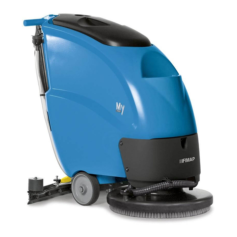
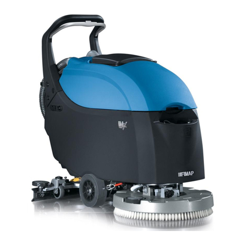
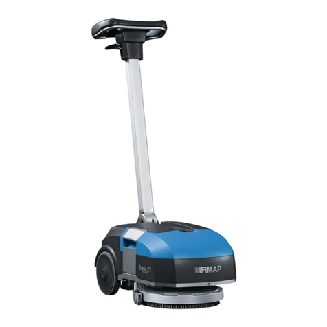
Fimap GL Pro User manual

ORIGINAL INSTRUCTION DOC. 10095239 - Ver. AA - 02-2020
PROFESSIONAL SCRUBBING MACHINES
USE AND MAINTENANCE MANUAL
GL Pro


CONTENTS
CONTENTS.............................................................................................................3
LOCATION OF THE MAIN MACHINE COMPONENTS .........................................5
GENERAL DESCRIPTION .....................................................................................5
GENERAL SAFETY REGULATIONS .........................................................................................5
DEFINITION OF LEVELS OF WARNING...................................................................................5
SYMBOLS USED IN THE MANUAL...........................................................................................6
PURPOSE AND CONTENT OF THE MANUAL .........................................................................6
TARGET GROUP........................................................................................................................6
PRESERVATION OF THE USER ...............................................................................................7
ON CONSIGNMENT OF THE MACHINE...................................................................................7
INTRODUCTORY COMMENT....................................................................................................7
IDENTIFICATION DATA..............................................................................................................7
TECHNICAL DESCRIPTION ......................................................................................................7
INTENDED USE .........................................................................................................................7
SAFETY ......................................................................................................................................7
REGULATIONS ..........................................................................................................................7
SERIAL NUMBER PLATE...........................................................................................................7
TECHNICAL DATA .................................................................................................8
GENERAL MACHINE DATA .......................................................................................................8
GENERAL MACHINE PERFORMANCE ....................................................................................8
MACHINE POWER SUPPLY TYPE............................................................................................8
SCRUBBING SYSTEM PERFORMANCE..................................................................................9
VACUUM HEAD PERFORMANCE.............................................................................................9
SYMBOLS AND LABELS USED ON THE MACHINE ...........................................9
SYMBOLS USED ON THE MACHINE .......................................................................................9
LABELS USED ON THE MACHINE ...........................................................................................9
CONTROL PANEL ....................................................................................................................10
CONTROL DISPLAY.................................................................................................................10
PREPARATION OF MACHINE ............................................................................. 11
HANDLING THE PACKAGED MACHINE .................................................................................11
HOW TO UNPACK THE MACHINE..........................................................................................11
HOW TO MOVE THE MACHINE..............................................................................................12
MACHINE SAFETY ..................................................................................................................12
TYPE OF BATTERY TO BE USED...........................................................................................12
BATTERY MAINTENANCE AND DISPOSAL ...........................................................................12
INSERTING THE BATTERIES INTO THE MACHINE ..............................................................12
CONNECTING THE BATTERIES TO THE MACHINE'S ELECTRICAL SYSTEM ...................13
RECHARGING THE BATTERIES.............................................................................................13
3

INSERTING WATER SYSTEM FILTER....................................................................................14
FILLING THE SOLUTION TANK ..............................................................................................15
DETERGENT SOLUTION ........................................................................................................15
ASSEMBLING THE BRUSH HEAD BRUSH ............................................................................15
PREPARING TO WORK .......................................................................................16
STARTING WORK ................................................................................................17
HOUR METER..........................................................................................................................17
BATTERY CHARGE LEVEL INDICATOR.................................................................................17
OVERFLOW DEVICE ...............................................................................................................17
WORKING PROGRAMS.......................................................................................18
SCRUBBING WITH DRYING....................................................................................................18
SCRUBBING WITHOUT DRYING ............................................................................................18
DRYING WITHOUT SCRUBBING ............................................................................................18
ADDITIONAL FUNCTIONS ..................................................................................19
ECO MODE ..............................................................................................................................19
MANUAL MODE .......................................................................................................................19
ADJUSTMENT OF THE DETERGENT SOLUTION FLOW......................................................20
SILENT-MAX FUNCTION .........................................................................................................20
ALARM SCREEN......................................................................................................................20
AT THE END OF THE WORK...............................................................................21
ROUTINE MAINTENANCE...................................................................................21
DRAINING THE RECOVERY TANK.........................................................................................22
CLEANING THE SQUEEGEE BODY .......................................................................................22
CLEANING THE BRUSH HEAD BRUSH .................................................................................22
CLEANING THE RECOVERY TANK FILTERS.........................................................................23
EMPTYING THE SOLUTION TANK .........................................................................................23
CLEANING THE WATER SYSTEM FILTER.............................................................................23
CLEANING THE VACUUM TUBE ............................................................................................23
EXTRAORDINARY MAINTENANCE....................................................................24
REPLACING THE SQUEEGEE BODY RUBBER BLADES .....................................................24
REPLACING THE BRUSH HEAD BRUSH...............................................................................24
CHOOSING AND USING BRUSHES ...................................................................25
TROUBLESHOOTING ..........................................................................................26
EC DECLARATION OF CONFORMITY ...............................................................28
4

LOCATION OF THE MAIN MACHINE COMPONENTS
The machine's main components are the
following:
1. Solution tank cap.
2. Solution tank.
3. Detergent solution lter.
4. Brush head body.
5. Solution tank dumping system.
6. Detergent solution tap.
7. Squeegee body.
8. Recovery tank cover.
9. Squeegee vacuum hose.
10. Suction motor tube.
11. Recovery tank.
12. Recovery tank handle.
13. Solution tank level hose.
14. Battery compartment closure carter.
15. Battery charging compartment closure carter.
16. Squeegee control pedal.
17. Control panel.
18. Dead man's lever.
19. Control column uncoupling lever.
The descriptions contained in this document are not binding. The company therefore reserves the right to make any modications at any time to
elements, details, or accessory supply, as considered necessary for reasons of improvement or manufacturing/commercial requirements. The
reproduction, even partial, of the text and drawings contained in this document is prohibited by law. The company reserves the right to make
any technical and/or supply modications. The images are shown as reference only and are not binding as to the actual design and/or
equipment.
GENERAL SAFETY REGULATIONS
Before using the machine, please read the following document carefully and follow the
instructions contained herein, along with the instructions in the document supplied with the
machine itself, "GENERAL SAFETY REGULATIONS" (document code 10083659).
DEFINITION OF LEVELS OF WARNING
DANGER: indicates an imminent dangerous situation that, unless avoided, will result in death or serious injuries.
WARNING: Indicates a potentially dangerous situation that, unless avoided, could cause death of serious injury.
ATTENTION: Indicates a potentially dangerous situation that, unless avoided, could cause slight or moderate injuries.
N.B.: instructs the reader to pay particular attention to the topic that follows.
GENERAL DESCRIPTION
5
1 8
17
2 9
18
3 10
19
4
511 146 12 157 13 16

PURPOSE AND CONTENT OF THE MANUAL
The aim of this manual is to provide customers with all the information needed to use the machine in the safest, most appropriate and most
autonomous way. This includes information concerning technical aspects, safety, operation, downtime, maintenance, spare parts and scrapping.
The operators and qualied technicians must carefully read the instructions in this manual before carrying out any operations on the machine.
If in doubt about the correct interpretation of instructions, contact your nearest FIMAP Customer Service Centre to obtain the necessary
clarications.
TARGET GROUP
This manual is written both for operators and for qualied machine maintenance technicians. Operators must not perform operations that should
be carried out by qualied technicians. The manufacturer is not liable for damages resulting from failure to comply with this veto.
SYMBOLS USED IN THE MANUAL
Open book symbol with an "i"
Indicates the need to consult the instruction manual.
Open book symbol
Tells the operator to read the user manual before using the device.
Covered place symbol:
The operations preceded by this symbol must always be carried out in a dry, covered area.
Information symbol:
Indicates additional information for the operator, to improve the use of the device.
Warning symbol:
Carefully read the sections preceded by this symbol meticulously following the instructions indicated for the safety of the operator
and the device.
Danger symbol (corrosive substances):
The operator should always wear protective gloves to avoid the risk of serious injury to the hands caused by corrosive substances.
Danger symbol (battery acid leakage):
Indicates the danger of leaking acid or acid fumes from the batteries while they are being recharged.
Danger symbol (moving carriages):
Indicates that the packed product should be handled with suitable carriages that conform to legal requirements.
Mandatory room ventilation symbol:
Informs the operator that the room must be ventilated while the batteries are being recharged.
Symbol indicating the compulsory use of protective gloves:
Indicates that the operator should always wear protective gloves, to avoid the risk of serious injury to his hands from sharp objects.
Symbol indicating the compulsory use of tools:
Informs the operator of the need to use tools not included with the machine.
Symbol indicating a treading ban:
Informs the operator that it is forbidden to tread on machine components, as this could lead to serious injury.
Recycling symbol:
Tells the operator to carry out the operations in compliance with environmental regulations in force in the place where the appliance
is being used.
Disposal symbol:
Carefully read the sections marked with this symbol for disposing of the appliance.
6

PRESERVATION OF THE USER
The Use and Maintenance Manual must be stored in its special pouch close to the machine, protected from liquids and anything else that could
compromise its legibility.
ON CONSIGNMENT OF THE MACHINE
When the machine is consigned to the customer, an immediate check must be performed to ensure all the material mentioned in the shipping
documents has been received, and also to check the machine has not suered damage during transportation. If this is the case, the carrier
must ascertain the extent of the damage at once, informing our customer service oce. It is only by prompt action of this type that the missing
material can be obtained, and compensation for damage successfully claimed.
INTRODUCTORY COMMENT
Any oor scrubbing machine can only work properly and eectively if used correctly and kept in full working order by performing the
maintenance operations described in the attached documentation. We therefore suggest you read this instruction booklet carefully and read it
again whenever diculties arise while using the machine. If necessary, remember that our assistance service (organised in collaboration with
our dealers) is always available for advice or direct intervention.
IDENTIFICATION DATA
For technical assistance or to request replacement parts, always give the model, the version and the serial number (written on the relevant
plate).
TECHNICAL DESCRIPTION
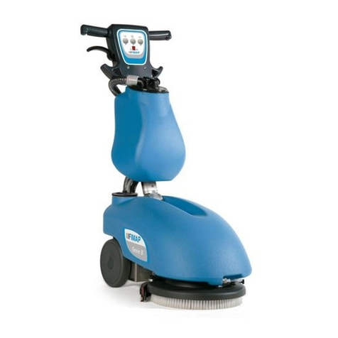
The GL Pro is a oor scrubbing machine that, together with the mechanical action of a brush with the addition of the chemical action of a
water-detergent solution, is able to clean a wide range of oors and types of dirt, using its forward movement to collect the removed dirt and the
detergent solution not absorbed by the oor. The machine must only be used for this purpose.
INTENDED USE
This scrubbing machine was designed and built for the cleaning (scrubbing and drying) of smooth, compact ooring in the commercial,
residential and industrial sectors by a qualied operator in proven safety conditions. The scrubbing machine is not suitable for cleaning rugs or
carpet oors. It is only suitable for use in closed (or at least covered) places.
ATTENTION: the machine is not suitable for use in the rain, or under water jets.
IT IS FORBIDDEN to use the machine in environments with an explosive atmosphere to clean dangerous powders or ammable liquids. In
addition, it is not suitable as a means of transport for people or objects.
SAFETY
Operator cooperation is paramount for accident prevention. No accident prevention programme can be eective without the full cooperation
of the person directly responsible for machine operation. The majority of occupational accidents that happen either in the workplace or whilst
moving are caused by failure to respect the most basic safety rules. An attentive, careful operator is most eective guarantee against accidents
and is fundamental in order to implement any prevention programme.
REGULATIONS
All references to forwards and backwards, front and rear, right and left indicated in this manual should be understood as referring to the operator
in the driving position, with his/her hands on the control column.
SERIAL NUMBER PLATE
11
10
9
8
7
6
1
2
3
4
5
The serial number plate is located inside the solution tank, and indicates the general
characteristics of the machine, in particular the serial number of the machine. The serial
number is a very important piece of information and should always be provided together with
any request for assistance or when purchasing spare parts. The serial number plate contains
the following:
1. The weight of the batteries that power the machine (expressed in kg).
2. The IP protection rating of the machine.
3. The gross weight of the machine (expressed in kg).
4. The machine ID code.
5. The machine serial number.
6. The machine ID name.
7. The nominal power consumed by the machine (expressed in W).
8. The maximum grade that the appliance can handle during work activities
(expressed in %).
9. The year of machine manufacture.
10. The nominal voltage of the machine (expressed in V).
11. The commercial name of the machine, and the manufacturer's address.
7
TECHNICAL DATA
GENERAL MACHINE DATA
DESCRIPTION U/M
[KMS] GL Pro
Nominal input power [IEC 60335-2-72; IEC 62885-9] kW 7,2
Solution tank capacity [IEC 62885-9] l 10
Solution tank volume l 17
Recovery tank capacity [IEC 62885-9] l 11
Recovery tank volume l 15
Minimum inversion corridor [IEC 62885-9] mm 900
Machine dimensions during work (length x height x width) mm
765
1110
490
Machine dimensions during transport [IEC 62885-9] mm 450
Battery compartment dimensions (length x height x width) mm
215
215
290
Machine net weight [IEC 62885-9] kg 52,5
Machine weight during transport [IEC 62885-9] kg 73,5
GVW [IEC 60335-2-72; IEC 62885-9] kg 84
Maximum specic pressure on wheels [IEC 62885-9] N/mm20,77
Sound pressure level in operator seat [ISO 11201] (LpA) dB 61,4
Sound power level [IEC 60335-2-72; IEC 62885-9; ISO 3744] (LwA) dB 73,9
Uncertainty KpA dB ±1,5
Hand-arm vibrations [IEC 60335-2-72; IEC 62885-9; ISO 5349-1] m/s20,48
Vibration uncertainty ±4%
IP test [IEC 60335-2-72; IEC 60529] IP X3
Electrical protection class (machine; on-board battery charge) [IEC 60335-2-72; IEC 60335-1] III ; ON
GENERAL MACHINE PERFORMANCE
DESCRIPTION U/M
[KMS] GL Pro
Productivity m2/h 1300
Estimated coverage m2/h 900
Maximum uphill gradient during transfer with machine in working order % 2
Maximum working slope % 2
Time taken to empty recovery tank [IEC 62885-9] min. 1:40
Water consumption [IEC 62885-9] ml/m220
Maximum ambient temperature for correct machine operation °C +40
Maximum ambient temperature for correct machine operation during scrubbing phase °C +10
MACHINE POWER SUPPLY TYPE
DESCRIPTION U/M
[KMS] GL Pro
Recommended battery capacity (C5) [IEC 62885-9] AhC5 28
Battery duration hh:mm 01:15
Battery charging time DOD 60% hh:mm 05:00
The batteries used are: AGM NP33-12
The battery charger used was: 24V - 5A
8

SCRUBBING SYSTEM PERFORMANCE
DESCRIPTION U/M
[KMS] GL Pro
Working width [IEC 62885-9] mm 355
Nominal power of brush motor/s [IEC 62885-9] W 440
Total width of brushes [IEC 62885-9] mm 1x355
Maximum free brush rotations rpm 140
Maximum force of the brush head on the oor N 245
Maximum pressure exerted by the brush head on the oor N/cm20,44
Maximum solution ow [IEC 62885-9] l/min 1.2
VACUUM HEAD PERFORMANCE
DESCRIPTION U/M
[KMS] GL Pro
Squeegee width mm 440
Drying track [IEC 62885-9] mm 435
Nominal power of vacuum motor(s) [IEC 62885-9] W 280
Maximum vacuum [IEC 62885-9; IEC 60312-1] kPa 6,8
Maximum air ow [IEC 62885-9] l/s 25
SYMBOLS USED ON THE MACHINE
Filter body position symbol:
Applied to the front of the machine to indicate the position of the solution tank lter.
Recovery tank drainage hose symbol:
Applied to the left-hand side of the machine to identify where to insert the dumping system tube for the solution tank.
Symbol for maximum temperature for lling the solution tank:
Located on the front of the machine to indicate the maximum temperature of the water for lling the solution tank safely.
Solution tank lling symbol:
Located on the left side of the machine's solution tank to indicate the amount of water or detergent solution in the tank. The symbol
on the side indicates that the tank is full to about a half of its capacity.
Solution tank lling symbol:
Located on the left side of the machine's solution tank to indicate the amount of water or detergent solution in the tank. The symbol
on the side indicates that the tank is full.
SYMBOLS AND LABELS USED ON THE MACHINE
LABELS USED ON THE MACHINE
Label indicating the need to read the Use and Maintenance Manual:
Applied in the vicinity of the steering column in order to remind the operator to read the user and maintenance manual before
using the machine.
Label indicating the need to read the Use and Maintenance Manual:
Used in the brush head body, and indicates the prohibition to approach the brush head while the brush is moving.
Usage warning label:
Used on the back of the machine. The label indicates the absolute prohibition to vacuum and/or collect waste in a solid and/or
liquid state that is incandescent and/or ammable and/or explosive.
9

CONTROL PANEL
1
2 6
5
4 7
3
The control panel is divided as follows:
1. Machine stand-by mode activation - deactivation button.
2. SILET - MAX function activation - deactivation button.
3. Control display.
4. Suction motor activation or deactivation button.
5. Eco mode program activation or deactivation button.
6. Button to increase the level increment of detergent solution on the brush.
7. Button to decrease the level increment of detergent solution on the brush
CONTROL DISPLAY
3
2
1The control display is divided in:
1. Symbol string.
2. Text string.
3. Battery charge level.
Battery gas emissions warning label:
Used on the back of the machine. The label indicates that while the battery is charging, highly ammable hydrogen vapours could
escape. The label indicates that before performing maintenance on the machine, disconnect battery power supply cable from the
machine's main cable. The label indicates that it is prohibited to charge the batteries if the battery charger power supply cable is
damaged.
Battery charging phase label:
Used on the back of the machine. The label indicates the phases to perform to charge the batteries (valid for versions without CB).
Machine starting instructions label:
Used on the back of the control column. The label indicates the phases for starting the machine for operation.
10

PREPARATION OF MACHINE
HANDLING THE PACKAGED MACHINE
The machine's overall weight including packaging is 65Kg. The external dimensions of the package are: width 58cm; length 88cm and height
76cm.
N.B.: it is recommended that all the packaging components be kept for any future machine transportation.
DANGER: Move the packaged product with handling equipment that complies with legal requirements regarding size and mass of the
packaging.
HOW TO UNPACK THE MACHINE
The machine is shipped in specic packaging. To remove it, proceed as follows:
1. Place the lower part of the outer packaging in contact with the oor.
N.B.: use the pictograms printed on the box as a reference.
2. Remove the outer package.
WARNING: the machine is contained in specic packaging materials, whose elements (plastic bags, staples, etc.) can pose potential
hazards, and must not be left within reach of children, disabled persons, etc.
ATTENTION: It is recommended to wear the appropriate PPE (Personal Protective Equipment), suitable for the work to be carried out.
3. Insert a ramp in the rear part of the machine.
ATTENTION: the ramp gradient must not be such as to cause damage to the machine as it comes down.
4. The machine is secured to the footboard with wedges that lock the wheels, remove these wedges.
5. Drive the machine down the ramp.
ATTENTION: during this operation, check there are no people or objects near the machine.
11
1
6
11
16 17
12 13 14 15
7 9 108
3 542
2
6 7
8
10
9
4
5
5
3
1
9
15
11 12 12
13 14

HOW TO MOVE THE MACHINE
To transport the machine safely, proceed as follows:
DANGER: before starting any task, make sure the current regulations concerning the safe transport of dangerous substances are
scrupulously observed.
1. Check to make sure that the solution tank and the recovery tank are empty. If this is not the case, empty them (see the sections titled
“EMPTYING THE SOLUTION TANK” and “EMPTYING THE RECOVERY TANK”).
2. Stand at the back of the machine.
3. Lift the squeegee body, press the “SQUEEGEE CONTROL” pedal (1) at the rear right of the machine (Fig.1).
4. Use a ramp to move the machine up onto the transport vehicle.
ATTENTION: during this operation, check there are no people or objects near the machine.
N.B.: the ramp gradient must not be such as to cause damage to the machine as it goes up.
5. Place the machine on the transport device, put the machine in stand-by by pressing the button (2) located on the control panel (Fig.2).
6. Press the uncoupling lever (3) (Fig.3) and turn the control column to the vertical position (Fig.4).
7. Press the uncoupling lever (4) (Fig.5) and open the battery compartment closing carter, using the handle (5) (Fig.6).
8. Disconnect the electrical connector from the machine's general system.
9. Reclose the battery compartment closure carter, make sure that the retainer system is correctly engaged.
WARNING: secure the device according to the directives in force in the country of use, so that it cannot slide or tip over.
MACHINE SAFETY
To ensure that work is carried out in the best safety conditions, proceed as follows:
1. Check to make sure that the solution tank and the recovery tank are empty. If this is not the case, empty them (see the sections titled
“EMPTYING THE SOLUTION TANK” and “EMPTYING THE RECOVERY TANK”).
2. Stand at the back of the machine.
3. Lift the squeegee body, press the “SQUEEGEE CONTROL” pedal (1) at the rear right of the machine (Fig.1).
4. Put the machine in stand-by by pressing the button (2) located on the control panel (Fig.2).
5. Press the uncoupling lever (4) (Fig.5) and open the battery compartment closing carter, using the handle (5) (Fig.6).
6. Disconnect the electrical connector from the machine's general system.
7. Reclose the battery compartment closure carter, make sure that the retainer system is correctly engaged.
TYPE OF BATTERY TO BE USED
CODE DESCRIPTION
229862 BATTERY KIT 12V 33Ah AGM
229891 BATTERY KIT 12V 26Ah Pb
229863 BATTERY KIT 12V 36Ah Pb
Used batteries must meet the requirements set out in DIN EN 50272-3 "Traction batteries for
industrial trucks".
To ensure proper performance, the machine must be powered with 24V.
The machine can be powered with the battery kits listed in the table to the side.
N.B.: it is recommended to use battery kit 12V 33Ah AGM.
BATTERY MAINTENANCE AND DISPOSAL
For battery maintenance and recharging, respect the instructions provided by the battery manufacturer. When the batteries reach the end of
their service life, they must be disconnected by a specialised and properly trained operator, and must be subsequently removed from the battery
compartment using suitable lifting devices.
N.B.: dead batteries are classied as dangerous waste and as such must be delivered to an authorised body for disposal.
INSERTING THE BATTERIES INTO THE MACHINE
The batteries must be housed in the special compartment at the rear of the machine and should be handled using lifting equipment that is
suitable in terms of both weight and its coupling system.
ATTENTION: It is recommended to wear the appropriate PPE (Personal Protective Equipment), suitable for the work to be carried out.
ATTENTION: to prevent an accidental short circuit use insulated tools to connect the batteries, and do not place or drop metal objects on
the battery. Remove rings, watches and any clothing with metal parts that may come into contact with the battery terminals.
12

The various phases for inserting the batteries in the battery compartment are as follows:
1. Make sure the machine is in a safe condition (read “MACHINE SAFETY”).
2. Move to the rear of the machine, press the uncoupling lever (4) (Fig.5) and open the battery compartment closing carter, using the handle
(5) (Fig.6).
N.B.: for battery maintenance and daily recharging, you must fully respect the indications provided by the manufacturer or retailer.
ATTENTION: all installation and maintenance operations must be carried out by specialised personnel.
N.B.: before installing the battery, clean the battery compartment.
N.B.: Check that the connectors on the cables supplied are functioning correctly.
ATTENTION: check that the characteristics of the battery that you are looking to use are appropriate for the type of work to be performed.
ATTENTION: Check the battery charge and the condition of the contacts on the battery.
N.B.: you are advised to only lift and move the batteries with lifting and transportation means suitable for the specic weight and size
ATTENTION: the lifting hooks must not damage the blocks, connectors or cables.
N.B.: Before inserting the batteries into the machine, remember to cover the terminals with a little grease to protect them against external
corrosion.
3. House the batteries in the compartment, positioning the poles “+” and “-“ opposite each other.
ATTENTION: The battery compartment cover acts as a support surface when it is in a horizontal position, and the handle (5) acts as a
reinforcement and therefore must be positioned perpendicularly to the oor.
RECHARGING THE BATTERIES
The batteries must be charged prior to rst use, and whenever they no longer provide sucient power to perform the desired work.
ATTENTION: The control board and the battery charger, if present on-board, are set for AGM batteries, contact the nearest FIMAP
service centre to modify the setting if you want to use another type of battery.
ATTENTION: to avoid any permanent damage to the batteries, it is essential to avoid their complete discharge; begin recharging them
within a few minutes of noting the "discharged batteries" signal.
ATTENTION: Never leave the batteries completely discharged, even if the machine is not being used.
1. Bring the machine to the battery recharging area.
ATTENTION: park the machine in an enclosed place, on a at and level surface; near the machine there must be no objects that could
either damage it, or be damaged through contact with it.
DANGER: the room used to recharge the batteries must be adequately ventilated to prevent the accumulation of gases that leak from
batteries.
2. Perform the procedure for securing the machine ( see the section titled “SECURING THE MACHINE”).
CONNECTING THE BATTERIES TO THE MACHINE'S ELECTRICAL SYSTEM
N.B.: The batteries should be connected so as to obtain a total voltage of 24V.
ATTENTION: It is recommended that the electrical connection operations be carried out by specialised and trained personnel.
ATTENTION: to prevent an accidental short circuit use insulated tools to connect the batteries, and do not place or drop metal objects on
the battery. Remove rings, watches and any clothing with metal parts that may come into contact with the battery terminals.
The various phases for inserting the batteries in the battery compartment are as follows:
1. Using the supplied jumper cable, connect the batteries to the “+” and “-” poles in series.
2. Connect the battery connector cable to the "+" and "-" poles in order to obtain the terminal voltage of 24V.
3. Connect the battery connector to the electrical system connector.
13

To recharge the batteries without the built-in battery charger, proceed as follows:
ATTENTION: the following operations must be carried out by qualied personnel. An incorrect connection of the connector may cause a
malfunction of the device.
3. Press the uncoupling lever (4) (Fig.5) and open the battery compartment closing carter, using the handle (5) (Fig.6).
• Disconnect the battery connector from the electric system connector.
• Connect the external battery charger cable to the battery connector.
N.B.: the coupling connector of the battery charger is consigned inside the bag containing this instruction booklet, and must be
assembled on the cables of the battery charger as indicated in the instructions.
DANGER: before connecting the batteries to the battery charger, make sure it is suitable for the batteries used.
N.B.: carefully read the use and maintenance instructions of the battery charger that is used for charging.
ATTENTION: Keep the battery compartment closing carter open for the entire duration of the battery recharging cycle to allow gas fumes
to escape.
• Once the recharge cycle has been completed, disconnect the battery charger's cable from the battery connector.
• Connect the battery connector to the electrical system connector.
• Reclose the battery compartment closure carter, make sure that the retainer system is correctly engaged.
To recharge the batteries with the on-board battery charger proceed as follows:
ATTENTION: the following operations must be carried out by qualied personnel. An incorrect connection of the connector may cause a
malfunction of the device.
N.B.: Carefully read the use and maintenance instructions of the battery charger that is used for charging, this document is delivered
along with the machine.
• Press the uncoupling lever (4) (Fig.5) and open the battery compartment closing carter, using the handle (5) (Fig.6).
• Turn the battery charge cover (6) as far as possible (Fig.7).
• Remove the cap that covers the battery charger socket (Fig. 8).
ATTENTION: before connecting the batteries to the battery charger, make sure it is suitable for the batteries used.
WARNING: Before inserting the battery charger power cable into the socket, verify that there is no condensate or other forms of liquids.
N.B.: the battery charger power cable is delivered inside the bag containing this instruction booklet.
• Plug the battery charger cable into the mains socket.
• Connect the battery charger's power cable to the socket on the battery charger itself.
ATTENTION: keep the recovery tank open for the duration of the battery recharging cycle to allow gas fumes to escape.
• When the recharge cycle is complete, disconnect the battery charger cable from the mains.
• Disconnect the battery charger's power cable from the socket on the battery charger itself.
• Reposition the cap in the battery charger socket.
• Reclose the battery charging cover, make sure that the retainer system is correctly engaged.
• Reclose the battery compartment closure carter, make sure that the retainer system is correctly engaged.
INSERTING WATER SYSTEM FILTER
Before using the machine for the rst time the water system lter needs to be reset, for shipping reasons the lter cartridge and the cap have
been removed. To insert the lter cartridge in the water system lter body proceed as follows:
1. Take the machine to the maintenance area.
2. Make sure the machine has been secured (see the section titled “SECURING THE MACHINE”).
ATTENTION: It is recommended to wear the appropriate PPE (Personal Protective Equipment), suitable for the work to be carried out.
3. Move to the front left of the machine and tighten the tap outow, turn the lever (7) located in the tap body clockwise (Fig.9).
4. Insert the lter cartridge (8) in the housing on the cap (9) (Fig.10).
N.B.: The o-ring gasket (10) in the lter cartridge must be inserted into its seat in the cap (Fig.10).
5. Screw the cap (9) onto the body of the lter (11) (Fig.11).
14

FILLING THE SOLUTION TANK
Before lling the solution tank, carry out the following steps:
1. Take the machine to the usual place for lling the solution tank.
2. Perform the procedure for securing the machine ( see the section titled “SECURING THE MACHINE”).
3. Move to the front of the machine and check that the water system lter cap (9) is tightened, otherwise tighten it (Fig.11).
The solution tank can be lled with water in two dierent ways:
• Removing the cap/measuring device (12) and lling the solution tank by means of a rubber hose or a bucket (Fig.12).
• Inserting the lling tube in the hole (13) located in the cap/measuring device (12) (Fig.13), the hole is able to support the lling tube by itself.
4. Fill with clean water, at a temperature no higher than 50°C (122°F) and no lower than 10°C (50°F). The amount inside the tank can be seen
by means of the level tube (14) on the left-hand side of the machine (Fig.14).
DETERGENT SOLUTION
After lling the solution tank with clean water, add the liquid detergent to the tank in the concentration and manner indicated on the detergent
manufacturer's label.
To prevent the formation of an excessive amount of foam that could damage the vacuum motor, use the minimum percentage of detergent
required.
ATTENTION: It is recommended to wear the appropriate PPE (Personal Protective Equipment), suitable for the work to be carried out.
ATTENTION: always use detergents whose manufacturer's label indicates their suitability for scrubbing machines. Do not use acid or
alkaline products or solvents without this indication.
ATTENTION: always use low-foam detergent. To avoid the production of foam, put a minimum quantity of antifoam liquid in the recovery
tank before starting to clean. Do not use pure acids.
ASSEMBLING THE BRUSH HEAD BRUSH
To t the brush on the brush head body, proceed as follows:
1. Release the control column from the vertical position, press the stop lever (3) (Fig.3) and turn the control column towards yourself (Fig.15).
2. Turn the column towards yourself to nd the optimal position, this position must provide a sensation of comfort when using the machine.
Once the ideal position has been found, release the stop lever (2) to lock the column.
3. Place the brush on the oor and place the brush head body over it (Fig.16).
4. Activate the machine by pressing the button (2) located on the control panel (Fig.2).
5. Press the operator presence lever (15) (Fig.17), the gearmotor will activate and the brush will be connected to the brush retainer plate.
ATTENTION: during this operation, check there are no people or objects near the machine.
15

PREPARING TO WORK
Before beginning to work, it is necessary to:
1. Move to the rear of the machine, press the uncoupling lever (1) (Fig.1) and open the battery compartment closing carter, using the handle
(2) (Fig.2).
ATTENTION: the following operations must be carried out by qualied personnel. An incorrect connection of the connector may cause a
malfunction of the device.
2. Connect the battery connector to the electrical system connector.
3. Reclose the battery compartment closure carter, make sure that the retainer system is correctly engaged.
4. Move to the front left of the machine and check that the water system lter cap (3) is closed, otherwise tighten it (Fig.3).
5. Move to the front left of the machine and check that the water tap is opened completely, turn the lever (4) clockwise (Fig.4).
6. Move to the front right of the machine and turn the squeegee support counter-clockwise (Fig.5).
7. Make sure the vacuum tube (5) is correctly connected to the sleeve on the squeegee body. If it isn't, connect it (Fig.6).
8. Remove the recovery tank cover (6) (Fig.7).
1. Make sure the recovery tank is empty. If this is not the case, empty it (read “EMPTYING THE RECOVERY TANK”).
2. Remove the oating guard (7) by turning it clockwise (Fig.8).
3. Make sure the suction motor lter (8) is correctly connected and is clean (Fig.9). Otherwise, clean it (see “CLEANING THE RECOVERY
TANK FILTERS”).
4. Make sure that the squeegee lter (9) is correctly connected and clean (Fig.10), otherwise clean it (see “CLEANING THE RECOVERY
TANK FILTERS”).
5. Ret the recovery tank cover.
6. Check that the amount of detergent solution present in the solution tank is sucient for the type of work to be performed. If this is not the
case, top up the solution tank (see the sections titled “FILLING THE SOLUTION TANK” and “DETERGENT SOLUTION”).
N.B.: The amount inside the tank can be seen by means of the level tube (10) on the left-hand side of the machine (Fig.11).
7. Check that the squeegee rubbers are in good working condition. If not, carry out maintenance (see “REPLACING THE SQUEEGEE BODY
RUBBER BLADES”).
8. Check the condition of wear of the brush, and if excessively worn perform maintenance (see “REPLACING THE BRUSH HEAD BRUSH”).
N.B.: The condition of wear of the brushes can be inspected by checking if the bristles are longer than 10mm, otherwise they must be
replaced (the brush has a tuft of yellow bristles, the total height of the tuft is 10mm).
16
1
6
11
1
2
5
10
2
7
3
8 9
4
10
5
4
9
3
7 8
2
6

STARTING WORK
The machine can be used in the following work modes:
• ECO MODE, see “ECO MODE”.
• MANUAL MODE, see “MANUAL MODE”.
The working program “SCRUBBING WITH DRYING" in “ECO MODE” will be taken as an example. To start working in this mode, proceed as
follows:
1. Make all the checks listed in “PREPARING TO WORK”.
2. Sit on the driver’s seat.
1. Release the control column from the vertical position, press the stop lever (1) (Fig.1) and turn the control column towards yourself (Fig.2).
2. Turn the column towards yourself to nd the optimal position, this position must provide a sensation of comfort when using the machine.
Once the ideal position has been found, release the stop lever (1) to lock the column.
3. Activate the machine by pressing the button (2) located on the control panel (Fig.3).
4. Lower the squeegee, activate the pedal (3) located at the rear right of the machine (Fig.4).
5. Activate the suction motor by pressing the button (4) located on the control panel (Fig.3).
6. Press the operator presence lever (5) (Fig.5).
7. As soon as the operator presence levers are pressed, the brush head motor and the suction motor will start working. As a result, also the
pump in the water system will start to operate and detergent solution will be delivered to the brush. During the rst few metres, check that
there is sucient solution and that the squeegee is drying correctly.
8. The machine will now begin to work with full eciency until the battery is at or until the detergent solution has nished.
HOUR METER
0.4
H
1 2
4 3
The machine control panel contains the control display, which shows the total usage time via a series of
numbers (1).
The digits that precede the "." symbol identify the hours, whereas the numbers that precede the “.” symbol
identify the tenths of an hour (a tenth of an hour corresponds to six minutes).
N.B.: When the “hour glass” symbol (2) is ashing it indicates that the hour meter is counting the
appliance's operating time.
BATTERY CHARGE LEVEL INDICATOR
The control display is on the control panel, the battery charge level can be seen at the bottom.
The indicator is composed of two charge level symbols, the rst represented by a graphic symbol (3), the second by a symbol that represents a
battery (4).
The graphic symbol (3) is composed of 9 charge levels, each of which represents a residual charge percentage.
When the residual charge is at 20% the battery symbol (4) starts to ash, in these conditions bring the machine to the area used for charging the
batteries.
N.B.: a few seconds after the battery charge level reaches 20%, the brush motor switches o automatically. With the remaining charge it
is still possible, however, to complete the drying process before recharging
N.B.: a few seconds after the battery charge level reaches 10%, the suction motor switches o automatically. With the remaining charge,
it is still possible, however, to move the machine to the location designated for its recharging.
OVERFLOW DEVICE
The standard model machine is NOT equipped with an overow device, because the volume of the recovery tank is larger than the capacity
of the solution tank. In extraordinary cases, there is a mechanical device (oat) under the recovery tank lid that, when the recovery tank is
full, shuts o the air to the vacuum motor intake to protect it; the sound of the suction motor will then be deeper. Empty the recovery tank (see
“EMPTYING THE RECOVERY TANK”).
17
5421 3
2
4
153

WORKING PROGRAMS
SCRUBBING WITH DRYING
To perform a scrubbing and drying program, proceed as follows:
1. Make all the checks listed in “PREPARING TO WORK”.
2. Sit on the driver’s seat.
1. Release the control column from the vertical position, press the stop lever (1) (Fig.1) and turn the control column towards yourself (Fig.2).
2. Turn the column towards yourself to nd the optimal position, this position must provide a sensation of comfort when using the machine.
Once the ideal position has been found, release the stop lever (1) to lock the column.
3. Activate the machine by pressing the button (2) located on the control panel (Fig.3).
4. Lower the squeegee, activate the pedal (3) located at the rear right of the machine (Fig.4).
5. Activate the suction motor by pressing the button (4) located on the control panel (Fig.3).
N.B.: As soon as the button (4) is pressed, “ON” will appear on the control display (Fig.5).
6. Press the operator presence lever (5) (Fig.6).
7. As soon as the operator presence levers are pressed, the brush head motor and the suction motor will start working. As a result, also the
pump in the water system will start to operate and detergent solution will be delivered to the brush. During the rst few metres, check that
there is sucient solution and that the squeegee is drying correctly.
8. The machine will now begin to work with full eciency until the battery is at or until the detergent solution has nished.
DRYING WITHOUT SCRUBBING
To perform a working program of only drying without scrubbing the oor, proceed as follows:
1. Make all the checks listed in “PREPARING TO WORK”.
2. Sit on the driver’s seat.
1. Release the control column from the vertical position, press the stop lever (1) (Fig.1) and turn the control column towards yourself (Fig.2).
2. Turn the column towards yourself to nd the optimal position, this position must provide a sensation of comfort when using the machine.
Once the ideal position has been found, release the stop lever (1) to lock the column.
3. Activate the machine by pressing the button (2) located on the control panel (Fig.3).
4. Adjust the detergent solution delivery level to “H2O 0”, press the button “-” repeatedly (6) (Fig.3) until “H2O 0” appears on the control
display.
SCRUBBING WITHOUT DRYING
To perform a scrubbing program without drying , proceed as follows:
1. Make all the checks listed in “PREPARING TO WORK”.
2. Sit on the driver’s seat.
1. Release the control column from the vertical position, press the stop lever (1) (Fig.1) and turn the control column towards yourself (Fig.2).
2. Turn the column towards yourself to nd the optimal position, this position must provide a sensation of comfort when using the machine.
Once the ideal position has been found, release the stop lever (1) to lock the column.
3. Activate the machine by pressing the button (2) located on the control panel (Fig.3).
4. Press the operator presence lever (5) (Fig.6).
5. As soon as the operator presence levers are pressed, the brush head motor and the suction motor will start working. As a result, also the
pump in the water system will start to operate and detergent solution will be delivered to the brush. During the rst few metres, check that
there is sucient solution.
6. The machine will now begin to work with full eciency until the battery is at or until the detergent solution has nished.
18
6
421 3
2
4 6
1
5
3
ON
5
H2o 1
7

ADDITIONAL FUNCTIONS
N.B.: The rst time one of the two symbols shown above in the control display are pressed, the current level of detergent solution will be
shown for two seconds (Fig.7).
5. Lower the squeegee, activate the pedal (3) located at the rear right of the machine (Fig.4).
6. Activate the suction motor by pressing the button (4) located on the control panel (Fig.3).
N.B.: As soon as the button (4) is pressed, “ON” will appear on the control display (Fig.5).
7. Press the operator presence lever (5) (Fig.5).
8. As soon as the operator presence levers are pressed, the brush head motor and the suction motor will start working, the pump in the water
system will not start to deliver detergent solution to the brush. During the rst few metres of work, check that the squeegee is frying properly.
9. The machine will now work at its maximum eciency level.
ATTENTION: The drying without scrubbing operation should only be carried out if the device was used
beforehand to carry out a scrubbing without drying operation.
ECO MODE
At the centre of the control panel is the ECO MODE button; pressing this will activate “ECO MODE”, a program which guarantees the best
possible performance in terms of consumption and cleaning.
To activate the ECO MODE program with the machine stopped and active, press the button (1) in the centre of the control panel (Fig.1).
N.B.: As soon as the button (1) is pressed, “ECO” will appear on the control display (Fig.2).
N.B.: As soon as the machine is activated by pressing the button (2) located on the control panel (Fig.1), ECO MODE will be
automatically loaded.
N.B.: To deactivate ECO MODE, press the button (1) in the centre of the control panel (Fig.1). As soon as the button (1) is pressed,
“ECO” will disappear from the control display (Fig.3).
N.B.: ECO MODE can also be deactivated by pressing one of the buttons (3) (Fig.1) used to adjust the supply of detergent solution to the
brush (see “ADJUSTMENT OF THE DETERGENT SOLUTION FLOW”).
N.B.: ECO MODE can also be deactivated by pressing the “SILENT/MAX” button (4) (Fig.1), which is used to adjust the suction motor
performance (see “SILENT/MAX FUNCTION”).
MANUAL MODE
To change from “ECO MODE” to “MANUAL MODE”, simply change one of the following parameters:
1. Adjusting the quantity of detergent solution present in the machine's water system by pressing the buttons (3) on the control panel (Fig.1)
(see “ADJUSTMENT OF THE DETERGENT SOLUTION FLOW”).
2. Adjusting the performance level of the suction motor, pressing the button (4) on the control panel (Fig.1) (see “SILENT/MAX FUNCTION”).
N.B.: When “MANUAL MODE” is active in the control display, “ECO” will disappear from the control display (Fig.2).
19
1
ECO
2
ALL_90
7
LO
4
H2o 1
3
Hi
5
1
4
2 3

SILENT-MAX FUNCTION
This machine has a SILENT-MAX function for reducing the noise generated by the suction motor. The SILENT function is always active in the
machine by default. To deactivate the SILENT function, press the button (4) on the control panel (Fig.2).
N.B.: When the SILENT function is active, "LO” will appear on the control display (Fig.4).
N.B.: When the MAX function is active, "HI” will appear on the control display (Fig.5).
ALARM SCREEN
If an error occurs, the control display will show the corresponding alarm screen (Fig. 6), the screen will remain visible until the error has been
resolved. When an error occurs, do as follows:
1. Stop the machine immediately.
2. If the error persists, switch o the machine and wait a few minutes before switching it back on.
3. If the error continues, read the following table:
CODE DESCRIPTION POSSIBLE CAUSE SOLUTION
ALL_3 Low voltage The function board has detected a low
battery voltage level.
Recharge the batteries, if the problem continues replace the
batteries.
ALL_49 Amperometric - brush
output 1
The function board has detected an
excessive load on the brush head group.
Stop the machine and lighten the pressure on the brush(es).
If the alarm continues, turn o the machine and contact the
nearest service centre.
ALL_52
Amperometric -
vacuum cleaner
output 1
The function board has detected an
excessive load on the vacuum head.
Stop the machine and check that the vacuum head is
not obstructed (see “SQUEEGEE BODY CLEANING”;
CLEANING THE RECOVERY TANK FILTERS “CLEANING
THE VACUUM TUBE”).
If the alarm continues, turn o the machine and contact the
nearest service centre.
ALL_90 Lever pushed
The function board detected that the
operator presence levers have been
pushed when starting the machine.
Release the operator presence levers.
WARNING: In the case of any other alarm screen other than those indicated above, turn o the machine and contact the nearest service
centre.
ADJUSTMENT OF THE DETERGENT SOLUTION FLOW
To adjust the ow of detergent solution during work, proceed as follows:
1. During the rst few working meters check that the amount of solution is sucient to wet the oor, but not enough to be collected by the
squeegee.
2. If the amount of solution that comes out is not right, use the “+” and “-” buttons (3) on the control panel to adjust it (Fig.1).
N.B.: The detergent solution ow regulation function is only active when the gearmotor in the brush head body is active.
N.B.: The rst time one of the two symbols shown above in the control display are pressed, the current level of detergent solution will be
shown for two seconds (Fig.3).
N.B.: The ow of detergent solution onto the brush can be adjusted to four levels, from “H2O 0” to a maximum of “H2O 3”. The level can
be seen by the text on the control display (Fig.3).
N.B.: If the ow is adjusted to “H2O 0” is no emission of detergent solution.
20
Other manuals for GL Pro
1
Table of contents
Other Fimap Scrubber manuals

Fimap
Fimap FIMOP User manual

Fimap
Fimap SMG120 B User manual

Fimap
Fimap MAXIMA BASE BT 2017 User manual

Fimap
Fimap GL Pro User manual

Fimap
Fimap SMG130 S User manual

Fimap
Fimap MY50 User manual

Fimap
Fimap FS50 H User manual

Fimap
Fimap FS80 User manual

Fimap
Fimap MAXIMA User manual

Fimap
Fimap MMg base User manual
Popular Scrubber manuals by other brands

Cleaning Machines
Cleaning Machines KRUGER KF43E manual

U.S. Products
U.S. Products Solus 310R Information and operating instructions

Electrolux Professional
Electrolux Professional WH5 500H user manual

Kärcher
Kärcher BR 550 BAT Product information

Nederman
Nederman FE840 PLUS Operation manual

Advance acoustic
Advance acoustic SC1500 Service manual