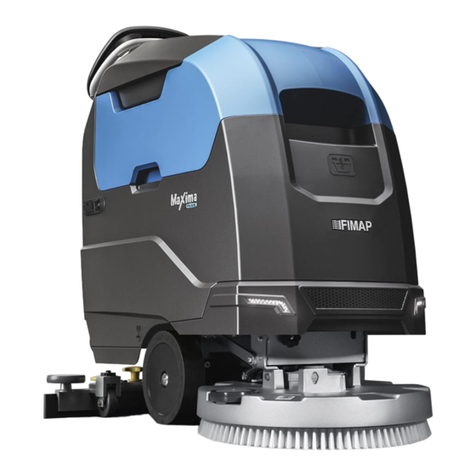
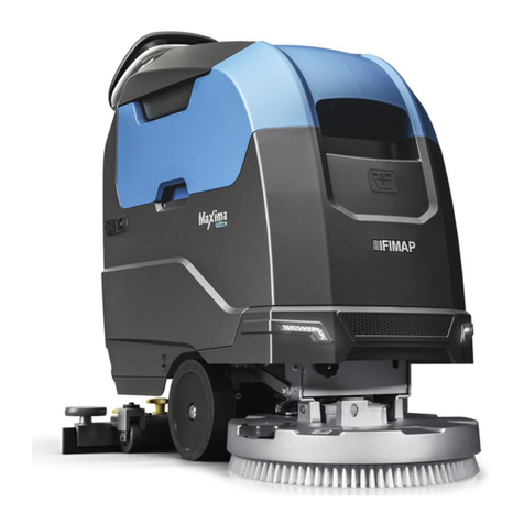
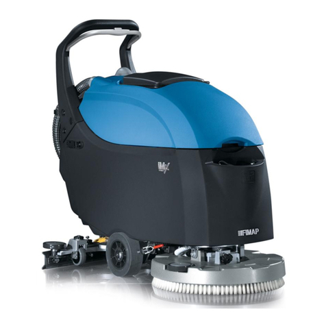
Fimap MxL Pro Series User manual

ORIGINAL INSTRUCTIONS DOC. 10084108 - Ver. AA - 01-2019
PROFESSIONAL SCRUBBING MACHINES
USE AND MAINTENANCE MANUAL
MxL Pro


MAIN MACHINE COMPONENTS
The machine's main components are the following:
1. Dead man's lever.
2. Control handlebars.
3. Eco Mode button.
4. Cover for FFM “FIMAP FLEET MANAGEMENT” SOS button
(Optional).
5. FFM “FIMAP FLEET MANAGEMENT” SOS button (Optional).
6. Control panel and control display.
7. Reverse control button.
8. FSS “FIMAP SOLUTION SAVER” control switch (optional) or FLR
“FIMAP LONG RANGE” control switch (optional).
9. Battery disconnect button.
10. “TANK CLEANING GUN” control switch (optional) or “LIQUID
VACUUM WAND” control switch (optional).
11. Support hook for recovery tank drainage tube.
12. Recovery tank drainage hose.
13. Solution tank level indicator.
14. Squeegee body control lever.
15. Main key switch.
16. Vacuum tube.
17. Solution tank drainage cap.
18. Squeegee body support.
19. Squeegee body.
20. Water ow adjustment tap.
21. Solution tank ller tube cap.
22. Cover cap for FFF “FIMAP FAST FILL” quick coupling kit
(optional).
23. Solution tank ller cap/measuring inlet.
24. Front headlights (optional).
25. Accessory compartment door.
26. Control handle for accessory compartment door.
27. Recovery tank cover lifting handle.
28. Recovery tank.
29. Recovery tank lifting handle.
30. Solution tank.
31. Electric brake control lever
32. Detergent solution lter.
3
20
18
17
16
19
30
27
25 26
28
29
24
23
22
21
2
73 654
1
10 9 8
13
11
12
14
15
31 32

CONTENTS
MAIN MACHINE COMPONENTS...............................................................................................3
CONTENTS.................................................................................................................................4
GENERAL SAFETY REGULATIONS .........................................................................................6
SYMBOLS USED IN THE MANUAL ..........................................................................................6
PURPOSE AND CONTENT OF THE MANUAL .........................................................................7
STORING THE USE AND MAINTENANCE MANUAL...............................................................7
ON CONSIGNMENT OF THE MACHINE ...................................................................................7
INTRODUCTORY COMMENT ....................................................................................................7
IDENTIFICATION DATA..............................................................................................................7
TECHNICAL DESCRIPTION ......................................................................................................7
INTENDED USE..........................................................................................................................7
SAFETY ......................................................................................................................................7
REGULATIONS...........................................................................................................................7
TARGET GROUP........................................................................................................................7
SERIAL NUMBER PLATE ..........................................................................................................8
TECHNICAL DATA .....................................................................................................................8
DISPOSAL ..................................................................................................................................9
SYMBOLS USED ON THE MACHINE .....................................................................................10
SYMBOLS PRESENT ON THE REGISTRATION PLATE.................................................................................... 10
SYMBOLS PRINTED ON THE MACHINE ........................................................................................................... 10
LABELS USED ON THE MACHINE..................................................................................................................... 10
SYMBOLS ON THE CONTROL PANEL................................................................................... 11
SYMBOLS ON THE CONTROL DISPLAY ............................................................................... 11
PREPARATION OF MACHINE .................................................................................................12
HANDLING THE PACKAGED MACHINE ............................................................................................................ 12
HOW TO UNPACK THE MACHINE ..................................................................................................................... 12
HOW TO MOVE THE MACHINE ......................................................................................................................... 13
MACHINE SAFETY.............................................................................................................................................. 14
TYPE OF BATTERY TO BE USED ...................................................................................................................... 14
BATTERY MAINTENANCE AND DISPOSAL....................................................................................................... 14
INSERTING THE BATTERIES IN THE MACHINE............................................................................................... 14
RECHARGING THE BATTERIES ........................................................................................................................ 14
ASSEMBLING THE BRUSH (SCRUBBING VERSION) ...................................................................................... 15
ASSEMBLING THE BRUSH (SWEEPING VERSION) ........................................................................................ 15
ASSEMBLING THE SQUEEGEE BODY.............................................................................................................. 16
INSERTING WATER SYSTEM FILTER ............................................................................................................... 16
FILLING THE SOLUTION TANK WITH WATER .................................................................................................. 16
DETERGENT SOLUTION (VERSIONS WITHOUT FSS) .................................................................................... 16
FILLING THE DETERGENT CANISTER (VERSIONS WITH FSS) ..................................................................... 17
PREPARING TO WORK ...........................................................................................................18
STARTING WORK ....................................................................................................................19
HOUR METER ..................................................................................................................................................... 20
BATTERY CHARGE LEVEL INDICATOR ............................................................................................................ 20
SCRUBBING WITH DRYING ............................................................................................................................... 20
SCRUBBING WITHOUT DRYING ....................................................................................................................... 20
DRYING................................................................................................................................................................ 21
ECO MODE.......................................................................................................................................................... 21
MANUAL MODE................................................................................................................................................... 21
PROGRAM ZONE MODE .................................................................................................................................... 21
ADJUSTMENT OF THE DETERGENT SOLUTION FLOW ................................................................................. 22
REGULATING THE FORWARD SPEED ............................................................................................................. 22
REVERSE GEAR ................................................................................................................................................. 22
4
EXTRA BRUSH HEAD PRESSURE FUNCTION................................................................................................. 22
SILENT-MAX FUNCTION..................................................................................................................................... 23
DETERGENT SOLUTION RECYCLING SYSTEM (FLR VERSIONS) ................................................................ 23
AUTOMATIC DETERGENT DOSING SYSTEM (FSS VERSIONS) .................................................................... 23
VACUUM WAND KIT............................................................................................................................................ 23
SPRAY GUN KIT .................................................................................................................................................. 24
ALARM SCREEN ................................................................................................................................................. 24
AUTOMATIC REQUEST FOR TECHNICAL ASSISTANCE (FFM VERSIONS) .................................................. 24
BATTERY DISCONNECT SWITCH ..................................................................................................................... 24
OVERFLOW DEVICE .......................................................................................................................................... 25
AT THE END OF THE WORK...................................................................................................25
RECOMMENDED MAINTENANCE OPERATIONS .................................................................26
CLEANING THE SQUEEGEE BODY................................................................................................................... 27
CLEANING THE DEBRIS HOPPER (SWEEPING VERSION) ............................................................................ 27
CLEANING THE BRUSH HEAD BRUSHES (SCRUBBING VERSION).............................................................. 27
CLEANING THE BRUSH HEAD BRUSHES (SWEEPING VERSION)................................................................ 27
DRAINING THE RECOVERY TANK .................................................................................................................... 28
CLEANING THE RECOVERY TANK FILTERS .................................................................................................... 28
CLEANING THE VACUUM TUBE........................................................................................................................ 28
EMPTYING THE SOLUTION TANK..................................................................................................................... 28
CLEANING THE WATER SYSTEM FILTER ........................................................................................................ 28
EXTRAORDINARY MAINTENANCE WORK ........................................................................... 29
REPLACING THE BRUSH (SCRUBBING VERSION)......................................................................................... 29
REPLACING THE BRUSH (SWEEPING VERSION)........................................................................................... 29
REPLACING THE SQUEEGEE BODY RUBBER BLADES................................................................................. 29
ADJUSTMENT INTERVENTIONS............................................................................................30
ADJUSTING THE SQUEEGEE BODY'S RUBBER BLADES .............................................................................. 30
CHOOSING AND USING BRUSHES .......................................................................................30
TROUBLESHOOTING ..............................................................................................................31
EC DECLARATION OF CONFORMITY ...................................................................................33
5

The descriptions contained in this document are not binding. The company therefore reserves the right to make any modications at any time to
elements, details, or accessory supply, as considered necessary for reasons of improvement or manufacturing/commercial requirements. The
reproduction, even partial, of the text and drawings contained in this document is prohibited by law.
The company reserves the right to make any technical and/or supply modications. The images are for reference purposes only, and
are not binding in terms of design and supply.
GENERAL SAFETY REGULATIONS
Before using the machine, please read the following document carefully and follow the
instructions contained herein, along with the instructions in the document supplied with the
machine itself, "GENERAL SAFETY REGULATIONS" (document code 10083659).
SYMBOLS USED IN THE MANUAL
Open book symbol with an "i":
Indicates the need to consult the instruction manual.
Open book symbol:
Tells the operator to read the user manual before using the device.
Covered place symbol:
The operations preceded by this symbol must always be carried out in a dry, covered area.
Information symbol:
Indicates additional information for the operator, to improve the use of the device.
Warning symbol:
Carefully read the sections preceded by this symbol meticulously following the instructions indicated for the safety of the operator and
the device.
Danger symbol (corrosive substances):
The operator should always wear protective gloves to avoid the risk of serious injury to the hands caused by corrosive substances.
Danger symbol (battery acid leakage):
Indicates the danger of leaking acid or acid fumes from the batteries while they are being recharged.
Danger symbol (moving carriages):
Indicates that the packed product should be handled with suitable carriages that conform to legal requirements.
Mandatory room ventilation symbol:
Informs the operator that the room must be ventilated while the batteries are being recharged.
Symbol indicating the compulsory use of protective gloves:
Indicates that the operator should always wear protective gloves, to avoid the risk of serious injury to his hands from sharp objects.
Symbol indicating the compulsory use of tools:
Informs the operator of the need to use tools not included with the machine.
Symbol indicating a treading ban:
Informs the operator that it is forbidden to tread on machine components, as this could lead to serious injury.
Recycling symbol:
Tells the operator to carry out the operations in compliance with environmental regulations in force in the place where the appliance is
being used.
Disposal symbol:
Carefully read the sections marked with this symbol for disposing of the appliance.
6

PURPOSE AND CONTENT OF THE MANUAL
The aim of this manual is to provide customers with all the information needed to use the machine in the safest, most appropriate and most
autonomous way. This includes information concerning technical aspects, safety, operation, downtime, maintenance, spare parts and scrapping.
The operators and qualied technicians must carefully read the instructions in this manual before carrying out any operations on the machine. If
in doubt about the correct interpretation of instructions, contact your nearest Customer Service Centre to obtain the necessary clarications.
STORING THE USE AND MAINTENANCE MANUAL
The Use and Maintenance Manual must be stored in its special pouch close to the machine, protected from liquids and anything else that could
compromise its legibility.
ON CONSIGNMENT OF THE MACHINE
When the machine is consigned to the customer, an immediate check must be performed to ensure all the material mentioned in the shipping
documents has been received, and also to check the machine has not suered damage during transportation. If this is the case, the carrier
must ascertain the extent of the damage at once, informing our customer service oce. It is only by prompt action of this type that the missing
material can be obtained, and compensation for damage successfully claimed.
INTRODUCTORY COMMENT
Any oor scrubbing machine can only work properly and eectively if used correctly and kept in full working order by performing the
maintenance operations described in the attached documentation. We therefore suggest you read this instruction booklet carefully and read it
again whenever diculties arise while using the machine. If necessary, remember that our assistance service (organised in collaboration with
our dealers) is always available for advice or direct intervention.
IDENTIFICATION DATA
For technical assistance or to request replacement parts, always give the model, the version and the serial number (written on the relevant
plate).
TECHNICAL DESCRIPTION
The MxL Pro is a oor scrubbing machine that can work on various types of oor and dirt thanks to the mechanical action of a brush and the
chemical action of a water-detergent solution. As it advances, it collects the dirt removed, along with the detergent solution not absorbed by the
ooring itself. The machine must only be used for this purpose.
INTENDED USE
This scrubbing machine was designed and built for the cleaning (scrubbing and drying) of smooth, hard ooring in the commercial, residential
and industrial sectors by a qualied operator in proven safety conditions. The scrubbing machine is not suitable for cleaning rugs or carpets. It
is only suitable for use in indoor (or at least covered) environments.
ATTENTION: the machine is not suitable for use in the rain, or under water jets.
ATTENTION: IT IS FORBIDDEN to use the machine for picking up dangerous dusts or inammable liquids in places with an explosive
atmosphere. In addition, it is not suitable as a means of transport for people or objects.
SAFETY
Operator cooperation is paramount for accident prevention. No accident prevention programme can be eective without the full cooperation
of the person directly responsible for machine operation. The majority of occupational accidents that happen either in the workplace or whilst
moving are caused by failure to respect the most basic safety rules. An attentive, careful operator is most eective guarantee against accidents
and is fundamental in order to implement any prevention programme.
REGULATIONS
All references to forwards and backwards, front and rear, right and left indicated in this manual should be understood as referring to the operator
in the driving position, with his/her hands on the control handlebars.
TARGET GROUP
This manual is written both for operators and for qualied machine maintenance technicians. Operators must not perform operations that should
be carried out by qualied technicians. The manufacturer is not liable for damages resulting from failure to comply with this veto.
7

TECHNICAL DATA
Remarks:
(1) The working capacity is calculated using a forward speed of 2.5 Km/h.
(2) The width of the squeegee refers to its maximum footprint.
(3) The width is to be understood as being without the squeegee mounted on the machine.
(4) Machine weight: refers to the overall machine weight without the batteries, and with both tanks empty.
(5) Machine weight during transport: refers to the overall machine weight with the batteries, but with both tanks empty.
TECHNICAL DATA Unit of
Measurement
MxL 65 Bt
Pro
MxL 75 Bt
Pro
MxL 85 Bt
Pro
MxL 70 Bts
Pro
Rated machine power W 1710 1710 1710 1610
Working capacity up to (1) m2/h 1638 1913 2100 1613
Working width mm 655 765 840 645
Squeegee width (2) mm 785 885 985 885
Brush head brush diameter (number - diameter) mm 2 / Ø340 2 / Ø400 2 / Ø430 -
Dimensions of cylindrical brush [number - (diameter - length)] mm - - - 2 / (Ø180 / 616)
Number of brush head brush rotations rpm 140 140 140 550
Brush head motor electrical properties [number / (voltage - rated power)] V / W 2 / (24 / 500) 2 / (24 / 500) 2 / (24 / 500) 2 / (24 / 450)
Debris hopper internal volume dm3- - - 8
Weight exerted on the brush head kg 33÷55 35÷57 38÷60 15÷40
Gradeability (weight(5)) % - - - -
Traction motor electrical properties [number / (voltage - rated power)] V / W 1 / (24 / 300) 1 / (24 / 300) 1 / (24 / 300) 1 / (24 / 300)
Forward speed (with transfer program active) Km/h 4,9 4,9 4,9 4,9
Suction motor electrical properties [number / (voltage - rated power)] V / W 1 / (24 / 422) 1 / (24 / 422) 1 / (24 / 422) 1 / (24 / 422)
Vacuum on vacuum head mBar 112 112 112 112
Maximum solution tank capacity l 74 74 74 74
Maximum recovery tank capacity l 85 85 85 85
Maximum solution tank capacity L 3 3 3 3
Machine dimensions (length - width(3) - height) mm 1497 - 701 -
1093 1514 - 795 - 1093 1542 - 878 - 1093 1471 - 733 - 1093
Battery compartment dimensions (length - width - useful height) mm 524 - 396 - 320 524 - 396 - 320 524 - 396 - 320 524 - 396 - 320
Electrical properties of recommended battery [number / (voltage / electric charge)] V / AhC54 / (6 / 180) 4 / (6 / 180) 4 / (6 / 180) 4 / (6 / 180)
Maximum individual battery weight (recommended) kg 31 31 31 31
Machine weight(4) kg 191 193 196 192
Machine weight during transport(5) kg 315 317 320 316
GVW kg 400 402 405 410
Sound pressure level (ISO 11201) - Lpa dB (A) <70 <70 <70 <70
Uncertainty Kpa dB (A) 1,5 1,5 1,5 1,5
Hand vibration level (ISO 5349) m/s2<2,5 <2,5 <2,5 <2,5
Vibration measurement uncertainty - - - -
SERIAL NUMBER PLATE
The serial number plate is positioned underneath the electrical system control panel inside the machine. It indicates the general machine
characteristics, in particular the serial number. The serial number is a very important piece of information and should always be provided
together with any request for assistance or when purchasing spare parts. The serial number plate contains the following:
1. The maximum weight of the batteries that power the machine
(expressed in kg).
2. The IP protection rating of the machine.
3. The gross weight of the machine (expressed in kg).
4. The machine ID code.
5. The machine serial number.
6. The machine ID name.
7. The nominal power consumed by the machine (expressed in W).
8. The maximum grade that the appliance can handle during
work activities (expressed in %).
9. The year of machine manufacture.
10. The nominal voltage of the machine (expressed in V).
11. The commercial name of the machine, and the manufacturer's
address.
Designby FIMAP Verona (Italy)
Assembledin FIMAP Verona (Italy)
ViaInvalidi del Lavoro, 1 S. Maria di Zevio - Verona - Italy
11
10
9
8
7
6
1
2
3
4
5
8

Remarks:
(1) The working capacity is calculated using a forward speed of 1.5 Km/h.
(2) The width of the squeegee refers to its maximum footprint.
(3) The width is to be understood as being without the squeegee mounted on the machine.
(4) Machine weight: refers to the overall machine weight without the batteries, and with both tanks empty.
(5) Machine weight during transport: refers to the overall machine weight with the batteries, but with both tanks empty.
TECHNICAL DATA Unit of
Measurement
MxL 65 Bt
Pro
MxL 75 Bt
Pro
MxL 85 Bt
Pro
MxL 70 Bts
Pro
Rated machine power W 1710 1710 1710 1610
Working capacity up to (1) sq.ft/h 17631 20591 22604 17362
Working width in 25,8 30,1 33,1 25,4
Squeegee width (2) in 30,9 34,8 38,8 34,8
Brush head brush diameter (number - diameter) in 2 / Ø13,39 2 / Ø15,75 2 / Ø16,93 -
Dimensions of cylindrical brush [number - (diameter - length)] in - - - 2 / (Ø7,09 / 24,25)
Number of brush head brush rotations rpm 140 140 140 550
Brush head motor electrical properties [number / (voltage - rated power)] V / W 2 / (24 / 500) 2 / (24 / 500) 2 / (24 / 500) 2 / (24 / 450)
Debris hopper internal volume ft3- - - 0,3
Weight exerted on the brush head lb 73÷121 77÷126 84÷132 33÷88
Gradeability (weight(5)) % - - - -
Traction motor electrical properties [number / (voltage - rated power)] V / W 1 / (24 / 300) 1 / (24 / 300) 1 / (24 / 300) 1 / (24 / 300)
Forward speed (with transfer program active) mph 3 3 3 3
Suction motor electrical properties [number / (voltage - rated power)] V / W 1 / (24 / 422) 1 / (24 / 422) 1 / (24 / 422) 1 / (24 / 422)
Vacuum on vacuum head mBar 112 112 112 112
Maximum solution tank capacity l 19 19 19 19
Maximum recovery tank capacity l 22 22 22 22
Maximum solution tank capacity l 0,8 0,8 0,8 0,8
Machine dimensions (length - width(3) - height) in 59 - 28 - 43 60 - 31 - 43 61 - 35 - 43 58 - 29 - 43
Battery compartment dimensions (length - width - useful height) in 20,6 - 15,6 - 12,6 20,6 - 15,6 -
12,6 20,6 - 15,6 - 12,6 20,6 - 15,6 - 12,6
Electrical properties of recommended battery [number / (voltage / electric charge)] V / AhC54 / (6 / 180) 4 / (6 / 180) 4 / (6 / 180) 4 / (6 / 180)
Maximum individual battery weight (recommended) lb 68 68 68 68
Machine weight(4) lb 421 426 432 423
Machine weight during transport(5) lb 694 699 706 697
GVW lb 882 886 893 904
Sound pressure level (ISO 11201) - Lpa dB (A) <70 <70 <70 <70
Uncertainty Kpa dB (A) 1,5 1,5 1,5 1,5
Hand vibration level (ISO 5349) m/s2<2,5 <2,5 <2,5 <2,5
Vibration measurement uncertainty - - - -
DISPOSAL
To dispose of the machine, take it to a demolition centre or an authorised collection centre. Before scrapping the machine,
it is necessary to remove and separate out the following materials, then send them to the appropriate collection centres in
accordance with the environmental hygiene regulations currently in force:
• Brushes
• Felt
• Electric and electronic parts*
• Batteries
• Plastic parts (tanks and handlebars)
• Metal parts (levers and frame)
(*) In particular, contact your distributor when scrapping electric and electronic parts.
9

SYMBOLS USED ON THE MACHINE
SYMBOLS PRESENT ON THE REGISTRATION PLATE
SYMBOLS PRINTED ON THE MACHINE
LABELS USED ON THE MACHINE
Direct current symbol:
Used on the machine's registration plate to indicate that it is powered by a DC power supply.
Battery symbol:
Used on the machine's registration plate to indicate the maximum weight of the batteries used to power the machine (expressed in
kg). The value refers to the batteries that the manufacturer oers.
X% Maximum gradient symbol:
Used on the machine serial number plate, to indicate the maximum gradient that can be safely handled in working mode.
Solution tank drain pipe symbol:
Located on the rear part of the machine, to identify the solution tank drainage point.
Recovery tank drainage hose symbol:
Located on the rear part of the machine, to identify the recovery tank drainage tube.
Cap/lter position symbol:
Located on the right-hand side of the machine to indicate the position of the detergent solution tank lter-cap.
Symbol of maximum temperature for lling the solution tank:
Located on the front of the machine to indicate the maximum temperature of the water for lling the solution tank safely.
Squeegee body working position symbol:
Located on the rear part of the machine, to indicate the squeegee control lever rotation direction for bringing the squeegee to its
working position.
Symbol for squeegee body idle:
Located on the rear part of the machine, to indicate the squeegee control lever rotation direction for bringing the squeegee to its idle
position.
Battery connection symbol:
Located on the front of the solution tank, to indicate how to connect the batteries in order to obtain a total voltage of 24V.
Label for detergent solution tap command:
Located on the right-hand side of the machine, to identify the control knob of the detergent solution tap.
Label for brush head tilt adjustment:
Located on the front of the machine, to identify the knob for adjusting the brush head body tilt.
Label indicating the need to read the Use and Maintenance Manual:
Axed to the machine in order to warn the operator to read the user and maintenance manual (this document) before using the
machine for the rst time.
Battery recharge hazard label:
Located inside the machine (above the electric system carter), to warn the operator of the possible risk during battery recharging
Battery recharge warning label:
Located inside the machine (above the electric system carter), to warn the operator when it's necessary to recharge the batteries.
Daily care warning label:
Applied to the machine to remind the operator of the applicable procedures for properly caring for the machine itself.
Machine use warning label:
Located on the rear of the machine, to warn the operator which substances cannot be removed with the machine.
Solution tank lter daily care warning label:
Applied to the machine to remind the operator to clean the solution tank after each use.
10

Moving brush hazard label:
Used on the machine to warn the operator not to place his/her hands near the moving brush.
Label warning about the risk of crushed hands:
Indicates danger to hands due to crushing between two surfaces.
Main switch symbol:
Located near the control panel, to indicate the main key switch.
SYMBOLS ON THE CONTROL PANEL
1. Reverse activation symbol.
2. Buttons for movement speed adjustment.
3. “ECO MODE” control button.
4. Brush head control button.
5. “AREA 2” program activation button.
6. “AREA 3” program activation button.
7. “AREA 1” program activation button.
8. “FNC” function activation-deactivation button.
9. Buttons for detergent solution adjustment.
10. Symbol for extra brush head pressure activation.
11. Control display.
3s.
10
11
1
8
7 6
5
4
3
9 2
SYMBOLS ON THE CONTROL DISPLAY
1. Detergent cleaning solution level indicator in the machine water circuit.
2. Indicator of the machine movement speed.
3. Indicator of the battery charge level.
4. Percentage value of the battery charge level.
5. Symbol indicating the hour meter is active.
6. Approximate hour meter value.
7. ECO-MODE active symbol.
8. Symbol indicating connection to the FFM system.
1
3
6
4
587
2
11

PREPARATION OF MACHINE
HANDLING THE PACKAGED MACHINE
The machine is contained in specic packaging, and since the packaging elements (plastic bags, staples, etc.) are a potential source of danger,
they should not be left within the reach of children, disabled persons, etc.
The machine's overall weight including packaging is 000Kg.
The overall dimensions of the package are: width=765mm length=1460mm height=1270mm.
N.B.: it is recommended that all the packaging components be kept for any future machine transportation.
ATTENTION: Move the packaged product with handling equipment that complies with legal requirements regarding size and mass of the
packaging.
HOW TO UNPACK THE MACHINE
The machine is shipped in specic packaging. To remove it, proceed as follows:
1. Place the lower part of the outer packaging in contact with the oor.
N.B.: Use the pictograms printed on the box as reference.
2. Remove the outer package.
CAUTION: these operations must be carried out using protective gloves to avoid any possible contact with the edges or tips of metal
objects.
3. Make sure the electric brake is engaged, then rotate the lever (1) in the direction of the arrow. The lever is located on the rear right-hand
side of the machine (Fig.1).
4. Check that the machine is o; if this is not the case, set the main switch to position "0" by turning the key (2) a quarter turn anti-clockwise
(Fig.2). Remove the key from the instrument panel.
5. Grip the handle (3) on the right-hand side of the recovery tank and turn the tank as far as it will go, until it reaches the maintenance position
(Fig.3).
6. Connect the battery hopper connector (4) to the connector of the general system (5) (Fig. 4).
CAUTION: This process must be carried out by qualied personnel.
12
5
7 8
2
8 9
10
9
11
223
13 18
2420
26 2927 30
19
25 28
21 22 23
1714 15 16
3
15
19
23
25
21
2825
20
29
2422
30 37
32 35
35
34
33 35
36 38
31 36
28
26 27 28
16
17 17
4
4
5
10
1
1
12
11
13
12
14
18
3s.
6
7
6

7. Grip the handle (3) and turn the recovery tank until it reaches the working position.
8. The machine is xed to the pallet by means of chocks, which block the wheels and brush head; remove these chocks.
9. Insert the starter key and turn on the machine; turn the main switch to the "I" position by turning the key (2) a quarter turn clockwise (Fig.5).
10. Lift the brush head body and press the “BRUSH HEAD CONTROL” button (6) on the control panel (Fig.6).
N.B.: as soon as the button (6) on the control panel is pressed, the green LED (7) (“BRUSH HEAD BODY WORK POSITION”) will switch
o (Fig.6).
11. Raise the squeegee body and turn the squeegee control lever (8) in the direction of the arrow (Fig.7). The lever is located on the back of the
machine.
12. Press the “REVERSE ACTIVATION - DEACTIVATION” button (9) on the control handlebars (Fig.8).
N.B.: As soon as the button (9) is pressed on the control panel, the “REVERSE ACTIVE” LED (10) on the control panel will be illuminated
(Fig.8).
13. Activate the dead man's lever (11) underneath the control handlebars (Fig.9) to start moving the machine in reverse.
14. Use a ramp to bring the machine down from the pallet.
CAUTION: do not t the brush and the rear squeegee body before unloading the machine, and avoid any violent jolts to the brush head
and squeegee support.
N.B.: the ramp gradient must not be such as to cause damage to the machine as it comes down.
15. Turn o the machine and turn the key (2) a quarter turn anticlockwise (Fig.2). Remove the key from the instrument panel.
16. Grip the handle (3) and turn the recovery tank as far as it will go to the maintenance position (Fig.3).
17. Disconnect the pad battery connector (4) from the main system connector (5) (Fig.4).
ATTENTION: This process must be carried out by qualied personnel.
18. Grip the handle (3) on the right-hand side of the recovery tank and turn the tank until it reaches the work position.
HOW TO MOVE THE MACHINE
To transport the machine safely, proceed as follows:
DANGER: before starting any task, make sure the current regulations concerning the safe transport of dangerous substances are
scrupulously observed.
1. Check to make sure that the solution tank and the recovery tank are empty. If this is not the case, empty them (see the sections titled
“EMPTYING THE SOLUTION TANK” and “EMPTYING THE RECOVERY TANK”).
2. Insert the key (2) into the main switch on the control panel. Bring the main switch to the "I" position by turning the key (2) a quarter turn
clockwise (Fig.5).
3. Lift the brush head body and press the “BRUSH HEAD CONTROL” button (6) on the control panel (Fig.6).
N.B.: as soon as the button (6) on the control panel is pressed, the green LED (7) (“BRUSH HEAD BODY WORK POSITION”) will switch
o (Fig.6).
4. Raise the squeegee body and turn the squeegee control lever (8) in the direction of the arrow (Fig.7). The lever is located on the back of the
machine.
5. When you push the dead man's lever (11) (Fig.9), the machine will begin to move.
6. Use a ramp to move the machine up onto the transport vehicle.
CAUTION: During this operation, check there are no people or objects near the machine.
N.B.: the ramp gradient must not be such as to cause damage to the machine as it goes up.
7. Position the machine on the means of transport, and set the main switch to the “0” position by turning the key (2) a quarter turn anti-
clockwise (Fig.2). Remove the key from the main switch.
8. Grip the handle (3) and raise the recovery tank to the maintenance position (Fig.3).
9. Disconnect the battery connector (4) from the main system connector of the machine (5) (Fig.4).
10. Grip the handle (3) and lower the recovery tank to its working position.
WARNING: secure the device according to the directives in force in the country of use, so that it cannot slide or tip over.
13

MACHINE SAFETY
To ensure that work is carried out in the best safety conditions, proceed as follows:
1. Make sure the electric brake is engaged, then rotate the lever (1) in the direction of the arrow. The lever is located on the rear right-hand
side of the machine (Fig.1).
2. Make sure the recovery tank is empty. If this is not the case, empty it using the tube (12) on the rear left-hand side of the machine (Fig.10)
(see "EMPTYING THE RECOVERY TANK").
3. Lift the brush head body and press the “BRUSH HEAD CONTROL” button (6) on the control panel (Fig.6).
N.B.: as soon as the button (6) on the control panel is pressed, the green LED (7) (“BRUSH HEAD BODY WORK POSITION”) will switch
o (Fig.6).
4. Raise the squeegee body and turn the squeegee control lever (8) in the direction of the arrow (Fig.7). The lever is located on the back of the
machine.
5. Turn o the machine and turn the key (2) a quarter turn anticlockwise (Fig.2). Remove the key from the instrument panel.
6. Grip the handle (3) on the right-hand side of the recovery tank (Fig.3) and turn the tank as far as it will go, until it reaches the maintenance
position.
7. Disconnect the battery connector (4) from the main system connector of the machine (5) (Fig.4).
ATTENTION: This process must be carried out by qualied personnel.
8. Grip the handle (3) on the right-hand side of the recovery tank and turn the tank until it reaches the work position.
TYPE OF BATTERY TO BE USED
Power to the machine must be supplied by two sealed traction batteries with gas recombination or gel technology. The batteries must meet
the requirements laid out in the norms: CEI EN 60254-1:2005-12 (CEI 21-5) + CEI EN 60254-2:2008-06 (CEI 21-7). In order to ensure good
operating performance, it is recommended to use four 6V MFP 180 Ah/C5 batteries.
BATTERY MAINTENANCE AND DISPOSAL
For battery maintenance and recharging, respect the instructions provided by the battery manufacturer. When the batteries reach the end of
their service life, they must be disconnected by specialized and properly trained personnel, and must be subsequently removed from the battery
compartment using suitable lifting devices.
N.B.: dead batteries are classied as dangerous waste and as such must be delivered to an authorised body for disposal.
INSERTING THE BATTERIES IN THE MACHINE
To t the batteries inside the machine, contact an FIMAP assistance centre technician.
The batteries should be connected so as to obtain a total voltage of 24V.
WARNING: FIMAP declines all responsibility for any damage to property or injury persons in the event that the batteries are replaced by
an unauthorized technician.
RECHARGING THE BATTERIES
The batteries must be charged prior to rst use, and whenever they no longer provide sucient power.
ATTENTION: to avoid any permanent damage to the batteries, it is essential to avoid their complete discharge; begin recharging them
within a few minutes of noting the "discharged batteries" signal.
ATTENTION: never leave the batteries completely discharged, even if the device is not being used.
1. Bring the machine to the battery recharging area.
2. Make sure the machine is in a safe condition (read “MACHINE SAFETY”).
ATTENTION: Park the machine in an enclosed place, on a at and level surface; near the machine there must be no objects that could
either damage it, or be damaged through contact with it.
ATTENTION: the room used to recharge the batteries must be adequately ventilated to prevent the accumulation of gases that leak from
batteries.
3. Grip the handle (3) and raise the recovery tank to the maintenance position (Fig.3).
To recharge the batteries without the built-in battery charger, proceed as follows:
ATTENTION: the following operations must be carried out by qualied personnel. An incorrect connection of the connector may cause
problems with machine functioning.
• Connect the external battery charger cable to the battery connector.
NOTE: the coupling connector of the battery charger is consigned inside the bag containing this instruction booklet, and must be
assembled on the cables of the battery charger as indicated in the instructions.
14

ATTENTION: Before connecting the batteries to the battery charger, make sure that this is suitable for the batteries being used.
NOTE: Carefully read the Use and Maintenance Manual of the battery charger to be used before carrying out the battery charge cycle.
• Grasp the handle (3) and turn to the charging position; the lower part of the recovery tank must be resting on the stop (13) (Fig.11).
CAUTION: keep the recovery tank open for the duration of the battery recharging cycle to allow gas fumes to escape.
• Once the recharge cycle has been completed, disconnect the battery charger's cable from the battery connector.
• Connect the electrical system connector to the battery connector.
• Grip the handle (3) and turn the recovery tank to its working position.
To recharge the batteries with the on-board battery charger proceed as follows:
ATTENTION: the following operations must be carried out by qualied personnel. An incorrect connection of the connector may cause
problems with machine functioning.
NOTE: Carefully read the Use and Maintenance Manual of the battery charger delivered with the machine before carrying out the battery
charge cycle.
CAUTION: before connecting the batteries to the battery charger, make sure it is suitable for the batteries used.
NOTE: The charger power cable is delivered inside the bag containing this instruction booklet.
• Connect the battery charger power supply cable to the cable on the battery charger itself.
• Plug the battery charger cable into the mains socket.
• Grasp the handle (3) and turn to the charging position; the lower part of the recovery tank must be resting on the stop (13) (Fig.11).
CAUTION: keep the recovery tank open for the duration of the battery recharging cycle to allow gas fumes to escape.
• When the recharge cycle is complete, disconnect the battery charger power supply cable from the mains.
• Disconnect the battery charger power supply cable from the cable on the battery charger itself.
• Grip the handle (3) and turn the recovery tank to its working position.
ASSEMBLING THE BRUSH (SCRUBBING VERSION)
To assemble the brushes to bush head body, which for reasons of packaging are supplied dismantled from the machine, proceed as follows:
1. Make sure the machine is in a safe condition (read “MACHINE SAFETY”).
CAUTION: users are advised to always wear protective gloves, to avoid the risk of serious injury to hands.
2. With the brush head in the raised position, remove the brush head splash guards (14) (Fig.12).
3. Insert the brush into the ange on the brush head body, press the brush-holder plate retainer (15) and simultaneously rotate the brush in the
direction shown in the image (Fig.13).
ATTENTION: Fig.13 shows the rotation direction of the left-hand brush, rotate in the opposite direction for the right-hand brush.
4. Repeat the operations completed for the right-hand front brush as well.
ASSEMBLING THE BRUSH (SWEEPING VERSION)
To assemble the brushes to bush head body, which for reasons of packaging are supplied dismantled from the machine, proceed as follows:
1. Perform the procedure for securing the machine ( see the section titled “SECURING THE MACHINE”).
CAUTION: users are advised to always wear protective gloves, to avoid the risk of serious injury to hands.
2. With the brush head raised from the oor, turn the knobs (16) that hold the left lateral carter (17) in place anti-clockwise (Fig.14).
3. Remove the left lateral carter (17) (Fig.15).
4. Insert the brush into the tunnel (Fig.16), taking care to ensure that the gearmotor shaft enters the slit in the brush itself.
5. Repeat the previously described operations for the right-hand side as well.
N.B.: In order to be installed correctly, the brushes must form an X when viewed from above in the forward direction of movement.
15

ASSEMBLING THE SQUEEGEE BODY
For packaging reasons, the squeegee body comes disassembled from the machine. In order to mount it on the squeegee support, do the
following:
1. Make sure the machine is in a safe condition (read “MACHINE SAFETY”).
CAUTION: these operations must be carried out using protective gloves to avoid any possible contact with the edges or tips of metal
objects.
2. Unscrew the knobs (18) in the squeegee body pre-assembly (Fig.17).
3. First of all, insert the left-hand pin (19) on the squeegee body in the left slit (20) in the squeegee support (Fig.18), so that the bushing (21)
adheres to the walls of the slit.
4. Repeat the same operation for the right pin.
5. Tighten the knobs (18) to x the squeegee body to the support.
6. Insert the vacuum tube (22) into the sleeve (23) in the squeegee body (Fig.19).
N.B.: the tube must be positioned behind the squeegee lifting chain.
N.B.: Although the squeegee comes pre-adjusted, it is nevertheless recommended to read the section entitled “ADJUSTING THE
SQUEEGEE BODY RUBBER BLADES”.
INSERTING WATER SYSTEM FILTER
Before using the machine for the rst time the water system lter needs to be reset, for shipping reasons the lter cartridge and the cap have
been removed. To insert the lter cartridge in the water system lter body proceed as follows:
1. Take the machine to the maintenance area.
2. Make sure the machine has been secured (see the section titled “SECURING THE MACHINE”).
CAUTION: users are advised to always wear protective gloves, to avoid the risk of serious injury to hands.
3. Insert the lter cartridge (24) in the housing on the cap (25) (Fig.20).
N.B.: The O-ring gasket in the lter cartridge should be inserted into its seat in the cap.
4. Go to the right-hand side of the machine and screw the cap (25) onto the body of the detergent solution lter (26) (Fig.21).
FILLING THE SOLUTION TANK WITH WATER
Before lling the solution tank, carry out the following steps:
1. Take the machine to the usual place for lling the solution tank.
2. Perform the procedure for securing the machine ( see the section titled “SECURING THE MACHINE”).
3. Check the solution tank drainage cap (27) (on the rear right-hand side of the machine) is tight. If this is not the case, turn it clockwise
(Fig.22).
4. Check the water system lter cap (25) (on the rear right-hand side of the machine) is tight. If this is not the case, turn it clockwise (Fig.21).
The solution tank can be lled with water in three dierent ways:
• Remove the cap-measuring device (28) (Fig. 23) and ll the solution tank by means of a rubber hose or a bucket.
• Using the ller hose (29) (Fig.24), which supports the water hose on its own, remember to remove the cap-measuring device (28) in order to
allow the air to vent properly.
• Using the optional automatic clean water rell system, connect the female connector on the tube to the male connector (30) on the machine
(Fig. 25); before connecting the tube, remember to remove the cap (31) and the cap-measuring device (28) to enable the air to be vented.
5. Fill with clean water, at a temperature not higher than 50°C and not lower than 10°C. The amount inside the tank can be seen by means of
the level tube (32) (Fig.26) on the rear of the machine.
DETERGENT SOLUTION (VERSIONS WITHOUT FSS)
After lling the solution tank with clean water add the liquid detergent to the tank in the concentration and manner indicated on the detergent
manufacturer's label. To prevent the formation of an excessive amount of foam that could damage the vacuum motor, use the minimum
percentage of detergent required.
CAUTION: protective gloves should always be worn before handling detergents or acidic or alkaline solutions, to avoid serious injury to the
hands.
CAUTION: Always use detergents which have a manufacturer's label that indicates that they are suitable for use with oor scrubbing
machines. Do not use acid or alkaline products or solvents without this indication.
ATTENTION: Acid or alkaline maintenance detergent tank be used with pH values between 4 and 10 and that do not contain: oxidising
agents, chlorine or bromine, formaldehyde, mineral solvents. The detergents used must be suitable for use with scrubbing machines.
16

FILLING THE DETERGENT CANISTER (VERSIONS WITH FSS)
After lling the solution tank with clean water, you must ll the detergent canister. Before lling the canister, carry out the following steps:
1. Take the machine to the usual place for lling the solution tank.
2. Perform the procedure for securing the machine ( see the section titled “SECURING THE MACHINE”).
3. Grip the handle (3) on the right-hand side of the recovery tank (Fig.3) and turn the tank as far as it will go, until it reaches the maintenance
position.
4. Disconnect the male insert (33) from the female insert (34) in the cap (35) of the detergent canister (36) (Fig.27).
ATTENTION: before pulling on the male insert, push the lever on the female insert.
5. Gripping the handle (37) on the detergent canister (36), remove the canister from the compartment in the solution tank (Fig.28).
6. Remove the cap (35) from the detergent canister (Fig.29).
7. Fill the canister with the required detergent, as indicated on the label supplied with the machine.
CAUTION: protective gloves should always be worn before handling detergents or acidic or alkaline solutions, to avoid serious injury to the
hands.
WARNING: always use low-foam detergent. To avoid the production of foam, put a minimum quantity of anti-foam liquid in the recovery
tank before starting to clean. Do not use pure acids.
WARNING: Always use detergents which have a manufacturer's label that indicates that they are suitable for use with oor scrubbing
machines. Do not use acid or alkaline products or solvents without this indication.
ATTENTION: the dosing system is suitable for frequent maintenance cleaning. Acid or alkaline maintenance detergent tank be used with
pH values between 4 and 10 and that do not contain: oxidising agents, chlorine or bromine, formaldehyde, mineral solvents. The
detergents used must be suitable for use with scrubbing machines. Wash the circuit with water after use if the system is not used daily.
The system can be excluded. In case of sporadic use of detergents with pH between 1-3 or 11-14, use the oor scrubbing machine in the
traditional way by adding the detergent in the clean water tank and excluding the dosing circuit.
8. Ensure that you tighten the cap (35) properly to avoid any leakage of liquid while working. Make sure the detergent suction lter (38) is
correctly positioned on the bottom of the canister (Fig.30).
9. Grip the canister handle (37) to replace the canister (36) in its compartment inside the solution tank.
10. Connect the male insert (33) to the female insert (34) in the cap (35) of the detergent canister (36).
11. Grip the handle (3) on the right-hand side of the recovery tank and turn the tank as far as it will go, until it reaches the work position.
CAUTION: always use low-foam detergent. To avoid the production of foam, put a minimum quantity of anti-foam liquid in the recovery
tank before starting to clean. Do not use pure acids.
N.B.: to make it easier to measure the detergent on the cap/measuring device, there are notches indicating the detergent percentage
quantities that can be used. The notches range from a minimum of 0.1% to a maximum of 0.5%.
17

Before beginning to work, it is necessary to:
1. Make sure the recovery tank is empty. If this is not the case, empty it (read “EMPTYING THE RECOVERY TANK”).
2. Check that the quantity of detergent solution present in the solution tank is suitable for the type of work to be carried out. If this is not the
case, ll the solution tank (see “THE SOLUTION TANK WITH WATER” and “DETERGENT SOLUTION (VERSIONS WITHOUT FSS)”
or “FILLING THE DETERGENT CANISTER (VERSIONS WITH FSS)”). Check the level tube (1) in the rear left-hand part of the machine
(Fig.1).
3. Check the rubber squeegee blades are in good working condition. If they aren't, replace them (see “REPLACING THE SQUEEGEE BODY
RUBBER BLADES”).
4. Check that the condition of the brush is suitable for work; if this is not the case, replace it (see “REPLACING THE BRUSH HEAD BRUSH
(SCRUBBING VERSION)” or “REPLACING THE BRUSH HEAD BRUSH (SWEEPING VERSION)”).
5. Check that the machine is o; if this is not the case, turn the key (2) a quarter turn anti-clockwise (Fig.2) . Remove the key from the
instrument panel.
6. Grip the handle (3) on the right-hand side of the recovery tank (Fig.3) and turn the tank as far as it will go, until it reaches the maintenance
position.
7. Connect the main system connector (4) to the battery connector (5) (Fig.4).
ATTENTION: This process must be carried out by qualied personnel.
8. Grip the handle (3) on the right-hand side of the recovery tank and turn the tank until it reaches the work position.
9. Make sure the electronic brake is engaged. If this is not the case, turn the lever (6) in the direction of the arrow. The traction gearmotor is
located on the right-hand side of the machine (Fig.5).
10. Check the water tap is fully open - the water adjustment knob (7) must be turned fully in the direction shown by the arrow (Fig.6).
11. Make sure the solution tank drainage cap (8) is closed. If it isn't, close it (Fig.7).
12. Make sure the water lter cap (9) is closed. If it isn't, close it (Fig.8).
13. Make sure the cap of the recovery tank drainage tube (10) is closed. If it isn't, close it (Fig.9).
14. Make sure the vacuum tube (11) is correctly connected to the sleeve (12) in the squeegee body. If it isn't, connect it (Fig.10).
15. Make sure the suction motor lter (13) is correctly connected and is clean (Fig.11). If it isn't, clean it (see “CLEANING THE RECOVERY
TANK FILTERS”).
16. Make sure the lter basin (14) is correctly connected and is clean (Fig.11). If it isn't, clean it (see “CLEANING THE RECOVERY TANK
FILTERS”).
PREPARING TO WORK
18
1
1
223
3
4
4
5
9
5 6
6
7
10
8
7
9
8
10 11
12
13
11 14

STARTING WORK
The machine can be used in the following work modes:
• ECO-MODE, read the section “ECO-MODE”;
• MANUAL MODE, read the section “MANUAL MODE”,
• PROGRAM ZONE, read the section “PROGRAM ZONE MODE”.
As an example, we will look at the program mode. To begin working in this mode, proceed as follows:
1. Make all the checks listed in “PREPARING TO WORK”.
2. Go to the driving position, behind the machine.
3. Turn on the machine and turn the key (1) a quarter turn clockwise (Fig.1).
4. When the display comes on, three screens appear in sequence:
• The rst screen displayed indicates the logo of the manufacturer of the machine.
• The second screen displayed indicates the name of the machine.
• The third screen displayed (Fig.2) indicates the characteristics of the machine's programming.
• The forth screen displays (Fig.3) identies the work panel.
5. Select the desired work area, press one of the three "ZONE" buttons (2) on the control panel (read paragraph “PROGRAM ZONE MODE”)
(Fig.4).
N.B.: When the machine is switched on with the "TRANSFER" working program active, pressing one of the "ZONE" keys (2) automatically
activates the "SCRUBBING WITHOUT DRYING" program.
19
7
29 30
9
10 11
19
9
37
38
39
15
17 21
28
34
35 36
2
3
5
8
6
4
1
12 13
1
1
22
3s.
3
3
12
14
5
6
2219
4
2
719
9
820
1618
1311
14
15
25
23
15
18
24
25
26
23
17 27
26 20
23
28
21
22
29
24 25
30
31
26 27
32 33

6. Lower the squeegee body and turn the squeegee control lever (3) in the direction of the arrow (Fig.5). The lever is located on the back of
the machine.
7. When the dead man's lever (4) is pressed, the machine will begin to move. The lever is located underneath the control handlebars (Fig.6).
N.B.: the gearmotor will only begin functioning, and the solenoid valve will only begin dispensing detergent solution, when the brush head
body is in its working position.
8. During the rst few metres, check that the detergent solution coming out is suitable for the task in hand. If it isn't, adjust it after reading the
section "REGULATING THE DETERGENT SOLUTION".
The machine will now begin to work with full eciency until the battery is at or until the detergent solution has nished.
During the rst few metres, check that there is sucient solution and that the squeegee is drying correctly.
N.B.: If the dead man's lever is released during the scrubbing with drying operation, the brush motor and the solenoid valve will be
deactivated. The suction motor will continue working until the squeegee control lever is rotated to bring it back to its idle position.
N.B.: if the squeegee body is raised during the scrubbing and drying operation, the suction motor will continue working at maximum speed
for a certain period of time, and then switch o. This ensures that all the liquid in the vacuum tube is eliminated.
N.B.: when lling the solution tank, it is good practice to empty the recovery tank using the special drainage hose.
HOUR METER
The machine control panel contains the control display, which shows the total usage time (5) (Fig. 3). The numbers before the “hourglass”
symbol identify tenths of an hour (a tenth of an hour corresponds to six minutes), while the other numbers identify the hours.
BATTERY CHARGE LEVEL INDICATOR
The machine instrument panel contains the control display. At the top right of the work screen, there is a graphic symbol (6) (Fig. 3) representing
the battery charge level indicator. The indicator is composed of 5 charge levels, each of which represents about 20% of residual charge. With a
residual charge of 20% the graphic symbol starts to ash and after a few second it will appear in larger dimensions in the middle of the screen,
under these conditions take the machine to the usual place to charge the batteries.
ATTENTION: a few seconds after the battery charge level reaches 20%, the brush motor switches o automatically. With the remaining
charge it is still possible, however, to complete the drying process before recharging
ATTENTION: a few seconds after the battery charge level reaches 10%, the suction motor switches o automatically. With the remaining
charge, it is still possible, however, to move the machine to the location designated for its recharging
SCRUBBING WITH DRYING
To perform a scrubbing and drying program, proceed as follows:
1. Make all the checks listed in “PREPARING TO WORK”.
2. Go to the driving position, behind the machine.
3. Turn on the machine and turn the key (1) a quarter turn clockwise (Fig.1).
4. Lower the brush head body, press the “BRUSH HEAD CONTROL” button (7) on the control panel (Fig.4).
N.B.: As soon as the button (7) on the control panel is pressed, the green LED (“BRUSH HEAD BODY WORK POSITION”) (8) will switch
on (Fig.4).
5. Lower the squeegee body and turn the squeegee control lever (3) in the direction of the arrow (Fig.5). The lever is located on the back of
the machine.
6. When the dead man's lever (4) is pressed, the machine will begin to move. The lever is located underneath the control handlebars (Fig.6).
N.B.: the gearmotor will only begin functioning, and the solenoid valve will only begin dispensing detergent solution, when the brush head
body is in its working position.
7. During the rst few metres, check that the detergent solution coming out is suitable for the task in hand. If it isn't, adjust it after reading the
section "REGULATING THE DETERGENT SOLUTION".
SCRUBBING WITHOUT DRYING
To perform a scrubbing only program, proceed as follows:
1. Make all the checks listed in “PREPARING TO WORK”.
2. Go to the driving position, behind the machine.
3. Turn on the machine and turn the key (1) a quarter turn clockwise (Fig.1).
4. Lower the brush head body, press the “BRUSH HEAD CONTROL” button (7) on the control panel (Fig.4).
N.B.: As soon as the button (7) on the control panel is pressed, the green LED (“BRUSH HEAD BODY WORK POSITION”) (8) will switch
on (Fig.4).
20
This manual suits for next models
4
Table of contents
Other Fimap Scrubber manuals

Fimap
Fimap FS80 User manual

Fimap
Fimap BMg Series User manual

Fimap
Fimap MR65 B User manual

Fimap
Fimap GMG PRO User manual

Fimap
Fimap MMg base User manual

Fimap
Fimap MMg Series User manual

Fimap
Fimap SMG130 S User manual

Fimap
Fimap SMG120 B User manual

Fimap
Fimap MAGNA 65 Operating instructions

Fimap
Fimap GL Pro User manual

Fimap
Fimap MINNY 20 User guide

Fimap
Fimap Maxima Base E User manual

Fimap
Fimap MAGNA User manual

Fimap
Fimap iMx 50BT User manual

Fimap
Fimap MAXIMA User manual

Fimap
Fimap MXR User manual

Fimap
Fimap MY 16 B User manual

Fimap
Fimap FIMOP User manual

Fimap
Fimap Genie XS User manual

Fimap
Fimap SMG120 B User manual