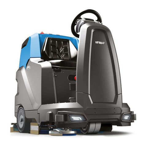
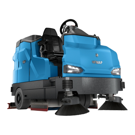
Fimap SMG120 B User manual

USE AND MAINTENANCE MANUAL
SMG120 B BASE
ED. 09-2019 ENG
ORIGINAL
INSTRUCTIONS
Doc. 10036957
Ver. AB

The descriptions contained in this document are not binding.
The company therefore reserves the right to make any modifications at any time to elements,
details, or accessory supply, as considered necessary for reasons of improvement or
manufacturing/commercial requirements.
The reproduction, even partial, of the text and drawings contained in this document is prohibited
by law.
The company reserves the right to make any technical and/or supply modifications. The images
are for reference purposes only, and are not binding in terms of design and supply.
Symbols used in the manual
Open book symbol with an “i”
Indicates the need to consult the instruction manual
Open book symbol
Used to tell the operator to read the manual before using the machine
Warning symbol
Carefully read the sections marked with this symbol and observe the
indications, for the safety of the operator and the machine
Warning symbol
Indicates danger of gas exhalation and leakage of corrosive liquids
Warning symbol
Indicates operator should take safety measures to avoid damage to
limbs.
Warning symbol
Indicates the danger of fire.
Keep naked flames at a safe distance
Warning symbol
Indicates that the packed product should be handled with suitable lifting
means that comply with the legal requirements
Disposal symbol
Carefully read the sections marked with this symbol, for machine
disposal

3
CONTENTS
ON CONSIGNMENT OF THE MACHINE.............................................................................................................................................5
SERIAL NUMBER PLATE.................................................................................................................................................................5
INTRODUCTORY COMMENT............................................................................................................................................................5
INTENDED USE ...............................................................................................................................................................................5
TECHNICAL DESCRIPTION............................................................................................. ERRORE. IL SEGNALIBRO NON È DEFINITO.
SYMBOLS USED ON THE MACHINE ................................................................................................................................................7
GENERAL SAFETY REGULATIONS ...............................................................................................................................................10
PREPARATION OF MACHINE ........................................................................................................................................................11
1.HANDLING THE PACKED MACHINE.......................................................................................................................................................................................................................11
2.HOW TO MOVE THE MACHINE................................................................................................................................................................................................................................11
3.INSTRUMENT PANEL COMPONENTS..................................................................................................................................................................................................................11
4.STEERING COLUMN COMPONENTS....................................................................................................................................................................................................................12
5.FOOTBOARD COMPONENTS...................................................................................................................................................................................................................................13
6.SEAT SUPPORT COMPONENTS.............................................................................................................................................................................................................................13
7.FRONT MACHINE COMPONENTS...........................................................................................................................................................................................................................14
8.BATTERY TYPE...............................................................................................................................................................................................................................................................14
9.BATTERY MAINTENANCE AND DISPOSAL........................................................................................................................................................................................................14
10.HANDLING - INSERTING BATTERIES.................................................................................................................................................................................................................14
11.CONNECTING THE BATTERIES AND BATTERY CONNECTOR................................................................................................................................................................15
12.CONNECTING THE BATTERY CHARGER.........................................................................................................................................................................................................16
13.BATTERY CHARGE LEVEL INDICATOR (BATTERY VERSION)................................................................................................................................................................16
14.SERVICE BRAKE – PARKING BRAKE.................................................................................................................................................................................................................17
15.WORKING FORWARD SPEED................................................................................................................................................................................................................................17
16.INCREASING THE PRESSURE ON THE BRUSH HEAD UNIT...................................................................................................................................................................18
17.SOLUTION TANK...........................................................................................................................................................................................................................................................18
18.FILLING THE DETERGENT SOLUTION TANK..................................................................................................................................................................................................18
19.REGULATING THE DETERGENT SOLUTION...................................................................................................................................................................................................18
20.RECOVERY TANK.......................................................................................................................................................................................................................................................19
21.ASSEMBLING THE SQUEEGEE.............................................................................................................................................................................................................................19
22.ADJUSTING THE SQUEEGEE INCLINATION...................................................................................................................................................................................................19
23.ADJUSTING THE SQUEEGEE HEIGHT..............................................................................................................................................................................................................19
24.ASSEMBLING THE BRUSHES...............................................................................................................................................................................................................................20
25.SAFETY BELT INSERTION (OPTIONAL)...........................................................................................................................................................................................................20
WORK...........................................................................................................................................................................................21
26.WORK...............................................................................................................................................................................................................................................................................21
27.BRAKING SYSTEM OIL LEVEL..............................................................................................................................................................................................................................22
28.CHOPPER CIRCUIT BOARD FAULT...................................................................................................................................................................................................................22
29.SOLUTION TANK EMPTY........................................................................................................................................................................................................................................22
30.BRUSH HEAD MOTOR UNDER PRESSURE...................................................................................................................................................................................................22
AT THE END OF THE WORK..........................................................................................................................................................23
31.AT THE END OF THE WORK..................................................................................................................................................................................................................................23
DAILY MAINTENANCE...................................................................................................................................................................24
32.CLEANING THE VACUUM MOTOR FILTER.....................................................................................................................................................................................................24
33.CLEANING THE RECOVERY TANK....................................................................................................................................................................................................................25
34.CLEANING THE SQUEEGEE..................................................................................................................................................................................................................................26
35.CLEANING THE SOLUTION TANK FILTER......................................................................................................................................................................................................26
WEEKLY MAINTENANCE...............................................................................................................................................................27
36.CLEANING THE VACUUM HOSE..........................................................................................................................................................................................................................27
37.CLEANING THE SOLUTION TANK........................................................................................................................................................................................................................27
38.BRUSH CLEANING.....................................................................................................................................................................................................................................................28
EXTRAORDINARY MAINTENANCE................................................................................................................................................29
39.REPLACING THE FRONT SQUEEGEE RUBBER...........................................................................................................................................................................................29
40.REPLACING THE REAR SQUEEGEE RUBBER..............................................................................................................................................................................................29
41.REPLACINGTHEREAR SPLASH GUARD RUBBERON THESIDECOVEROF THE BRUSH HEAD................................................................................................29
42.REPLACINGTHE FRONT SPLASH GUARD RUBBER ON THESIDECOVEROFTHE BRUSH HEAD.............................................................................................30
4
43.ADJUSTING THE HEIGHT OF THE SIDE SPLASH GUARDS.....................................................................................................................................................................31
TROUBLESHOOTING.....................................................................................................................................................................32
44.THE MACHINE DOES NOT START......................................................................................................................................................................................................................32
45.INSUFFICIENT WATER ON THE BRUSHES....................................................................................................................................................................................................32
46.THE SQUEEGEE DOES NOT DRY PERFECTLY...........................................................................................................................................................................................32
47.THE MACHINE DOES NOT CLEAN WELL.........................................................................................................................................................................................................32
48.EXCESSIVE FOAM PRODUCTION......................................................................................................................................................................................................................32
49.THE VACUUM CLEANER DOES NOT FUNCTION.........................................................................................................................................................................................32
50.THE BRUSH MOTOR DOES NOT WORK..........................................................................................................................................................................................................32
51.ELECTRIC FUSES AND THERMAL CUT-OUTS..............................................................................................................................................................................................33
52.ALARMS..........................................................................................................................................................................................................................................................................33
DISPOSAL..................................................................................................................................................................................... 34
CHOOSING AND USING THE BRUSHES.........................................................................................................................................35
EC DECLARATION OF CONFORMITY............................................................................................................................................36

5
On consignment of the machine
When the machine is consigned to the customer, an immediate check
must be performed to ensure all the material mentioned in the shipping
documents has been received, and also to check the machine has not
suffered damage during transportation. If this is the case, the carrier must
ascertain the extent of the damage at once, informing our customer
service office. It is only by prompt action of this type that the missing
material can be obtained, and compensation for damage successfully
claimed.
Serial number plate
Introductory comment
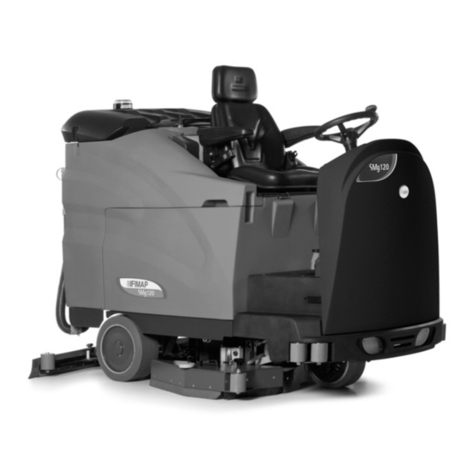
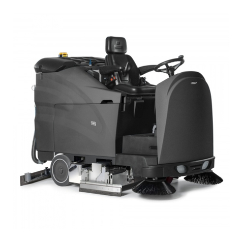
The SMg 120 Base is a floor scrubbing machine which, by means of the
mechanical action of the rotating brush and the chemical action of a
water/detergent solution, can clean any type of flooring. As it advances, it
also collects any removed dirt as well as the detergent solution not
absorbed by the floor.
The machine must only be used for this purpose. Even the best
machines will only work well if used correctly and kept in good working
order. We therefore recommend you read this instruction booklet
carefully, and consult it whenever difficulties arise while using the
machine. If necessary, remember that our customer assistance service
(organised in collaboration with our dealers) is always available for advice
or direct intervention.
Intended use
The floor scrubbing machine is designed for the professional cleaning of
surfaces and floors in industrial, commercial and public environments
only. It is only suitable for use in closed (or at least covered) places.
The machine is not suitable for use in the rain, or under water jets. IT IS
FORBIDDEN to use the machine for picking up dangerous dusts or
inflammable liquids in places with an explosive atmosphere. In addition, it
is not suitable as a means of transport for people or objects.

6
TECHNICAL DESCRIPTION U/M SMg 120 BASE
Nominal input power [IEC 60335-2-72; IEC 62885-9] kW 4,97
Working width mm 1200
Squeegee width mm 1266
Working capacity, up to m2/h 7250
Disc brush No. /mm 2 / 610
Disc brush rotations rpm 130
Brush motor V/W 36/2000
Force exerted on the brush (step-01; step-02; step-03) N 1275; 1375; 1470
Traction motor V/W 36 / 1500
Traction wheel (diameter / width) mm / mm 300 / 120
Maximum forward speed km/h 6,7
Maximum gradient with full load % 10
Suction motor No./(V/W) 2 / (36 / 650)
Maximum vacuum [IEC 62885-9; IEC 60312-1] kPa 17,6
Rear elastic wheels (diameter / width) mm / mm 370 / 140
Solution tank l 280
Recovery tank l 335
Steering diameter mm 3450
Machine dimensions (Length / Height / Width) mm 2160x1675x1340
Battery compartment dimensions (Length / Height / Width) mm 540x530x745
Recommended battery box (4 PZS 360) V / AhC536 / 360
Recommended battery box dry weight kg 420
Machine weight when empty kg 650
Transported machine weight kg 1070
Gross weight of the machine ready for use kg 1415
Sound pressure level in operator seat [ISO 11201] (LpA) dB 68.5
Uncertainty KpA dB 1.4
Whole body vibrations [IEC 60335-2-72; IEC 62885-9; ISO 2631-1] m/s2<0,5
Hand-arm vibrations [IEC 60335-2-72; IEC 62885-9; ISO 5349-1] m/s2<2.5
Uncertainty 3.5%

7
SYMBOLS USED ON THE MACHINE
Main switch or key switch symbol
Used on the instrument panel, to indicate the key switch for machine operation on (ON-I) or off (OFF-0)
Symbol denoting horn
Used to indicate the acoustic alarm button
Symbol denoting forwards and backwards speed selector
Used on the instrument panel, to indicate the speed of the forwards or backwards movements of the machine
Symbol denoting pressure applied to the brushes
Used to indicate the knob for increasing the brush pressure
Brush head / squeegee operating symbols
Used to indicate the I-DRIVE programs selector
Symbol denoting incorrect functioning
Used on the instrument panel to indicate the red warning light showing incorrect machine traction functioning
Symbol denoting ammetric check of the brush motor
Used on the instrument panel, for the red indicator light showing the brush motor is under pressure (force)
Symbol denoting parking brake engaged or incorrect braking system fluid level
Used on the instrument panel to indicate the red warning light showing the engagement of parking brake or the absence of oil in
the work braking system
Symbol denoting solution tank empty
Used on the instrument panel to indicate the red warning light showing a low level of water/detergent solution in the solution
tank

8
SYMBOLS USED ON THE MACHINE
Symbol denoting recovery tank rotation
Used on the instrument panel, for the green indicator light indicating rotation consent to recovery tank
Symbol denoting tap regulation
Used on the central panel of the steering cover, to indicate the tap knob to regulate the detergent
Parking brake pedal symbol
Used on the solution tank to indicate the position of the parking brake pedal
Symbol denoting the machine's power supply voltage
Used on the front of the machine, in correspondence with the battery charger socket insertion nozzle, to indicate the machine's
power supply voltage
Label warning operator to take safety measures to avoid damage to limbs
Label indicating the position of the quick release coupling for filling the solution tank
Symbol indicating the maximum temperature of the water used to fill the solution tank
Symbol indicating the position of the solution tank drain pipe
Symbol indicating the position of the recovery tank drainage tube
Indicates the maximum gradient

9
SYMBOLS USED ON THE MACHINE
Label relating to uncoupling the seat support
Displayed on the seat support to indicate the uncoupling handle
Symbol denoting treading ban
Used to indicate the area of the machine on which it is forbidden to tread or stand
Label indicating the position of the suction motor thermal circuit breakers

10
GENERAL SAFETY REGULATIONS
Before using the machine, please read the following document carefully and follow the
instructions contained herein, along with the instructions in the document supplied with
the machine itself, “GENERAL SAFETY REGULATIONS” (document code 10083659).

11
PREPARATION OF MACHINE
1. HANDLING THE PACKED MACHINE
The machine is contained in specific packaging with a pallet for the handling with fork trucks. The
packages CANNOT be placed on top of each other.
The total weight of the machine and packaging is 680kg.
The packaging dimensions are as follows:
SMG120 B
A: 1620mm
B: 1520 mm
C: 2380 mm
A
CB
1. Remove the outer packaging
2. The machine is fixed to the pallet with wedges which block the wheels
3. Remove the wedges
4. Use a chute to get the machine down from the pallet, pushing it backwards. Do not assemble the rear
squeegee before unloading the machine, and avoid violently jolting the brush head. To assemble the
squeegee, read the section “ASSEMBLING THE SQUEEGEE”.
5. Keep the pallet for any future transport needs
ATTENTION: If the product is delivered in cardboard containers, handle the
packed product with suitable lifting means that comply with the legal
requirements.
ATTENTION: During this operation, check there are no people or objects near
the machine.
2. HOW TO MOVE THE MACHINE
1. Make sure the solution tank and the recovery tank are empty
2. Check that the detergent canister is empty
3. Check that the brush head and squeegee are in the raised position
4. Place it on a pallet using a chute
5. Check that the key switch is in the “0” position and remove the key
6. Engage the parking brake
7. Secure the machine to the pallet using wooden wedges
3. INSTRUMENT PANEL COMPONENTS
The instrument panel components are identified as follows:
1. 3-way knob to set working speed
2. Main key switch
1
2

12
PREPARATION OF MACHINE
3. Level indicator for battery/hour meter
4. Red warning light indicating that there is a malfunction in the machine traction
5. Red indicator light, indicates that the parking brake is engaged or indicates the machine's braking
system oil reserve level
6. Red warning light indicating that the brush head motor is working under pressure (force)
7. Red indicator light, indicates that the detergent solution has reached the reserve level
8. Green indicator light, indicates consent to rotate the recovery tank
9. 3-way knob to set force applied to brushes during operation
10.Horn button
11.Working program adjustment switch, I-Drive device
Choose the desired working program with the I-Drive device:
A
.Transfer: movement of the machine without working
B. Drying: use the squeegee only
C
.Central brushes Scrubbing / Drying: use both the brushes and the squeegee
D. Central brushes moved to the side Washing / Drying: use of both the brushes that have been moved
laterally to the right and the squeegee (valid only for SMG120 EM)
E. Scrubbing only: use brushes only
4. STEERING COLUMN COMPONENTS
The steering column components on the left side are identified as follows:
12.suction motor thermal circuit breakers
13.Detergent delivery regulating knob
4
3
5
13
12
6
7
8
9
11
10

13
PREPARATION OF MACHINE
5. FOOTBOARD COMPONENTS
The components at the front right of the footboard are identified as follows:
14.Forward movement pedal
15.Backward movement pedal
16.Brake pedal
17.Parking brake pedal
18.Battery charger plug insertion hatch
6. SEAT SUPPORT COMPONENTS
The seat support components are identified as follows:
19.Seat lifting handle
20.Safety belt (optional)
21.Solution tank drain pipe
22.Recovery tank drainage tube
23.Recovery tank discharge cap
16 15
14
18
17
10
19
21
22
23

14
PREPARATION OF MACHINE
24.Blinking light
25.Water/detergent solution filler cap
26.Rapid refill kit (optional)
7. FRONT MACHINE COMPONENTS
The front components of the machine are identified as follows:
27.Headlights (optional)
8. BATTERY TYPE
To power the machine it is necessary to use:
liquid electrolyte lead traction batteries;
sealed traction batteries with gas recombination or gel technology.
OTHER TYPES MUST NOT BE USED.
The batteries must meet the requirements laid out in the norms: CEI EN 60254-1:2005-12 (CEI 21-5) + CEI
EN 60254-2:2008-06 (CEI 21-7)
For a good operating performance, we suggest the use of two 18V 360 Ah/C5 battery cases
9. BATTERY MAINTENANCE AND DISPOSAL
For maintenance and recharging, respect the instructions provided by the battery manufacturer.
Particular attention must be paid when choosing the battery charger, if not supplied, since there are
different kinds according to the type and capacity of the battery.
When the battery reaches the end of its working life, it must be disconnected by expert, trained personnel
then removed from the battery compartment with the aid of suitable lifting devices. EXHAUSTED
BATTERIES ARE CLASSIFIED AS DANGEROUS WASTE AND MUST BE CONSIGNED TO THE
A
UTHORISED BODIES FOR CORRECT DISPOSAL.
ATTENTION: users are advised to always wear protective gloves, to avoid the
risk of serious injury to hands.
ATTENTION: you are advised to only lift and move the batteries with lifting and
transportation means suitable for the specific weight and size.
10. HANDLING - INSERTING BATTERIES
The batteries must be housed in the special compartment beneath the seat casing. They should be
handled using lifting equipment that is suitable in terms of both weight and coupling system. They must
also satisfy the requirements of Standard CEI 21-5. The dimensions of the battery compartment are:
740mm x 540mm x H525mm.
ATTENTION: for battery maintenance and daily recharging, you must fully
respect the indications provided by the manufacturer or retailer. All installation
and maintenance operations must be carried out by specialised personnel.
24
25
26
27

15
PREPARATION OF MACHINE
ATTENTION: You are advised to use airtight batteries only, to avoid the
leakage of acids!
ATTENTION: users are advised to always wear protective gloves, to avoid the
risk of serious injury to hands.
To insert batteries proceed as follows:
1. Lock the machine using the parking brake, by pressing down on the pedal (1) and moving it towards
the rear of the machine
2. Make sure the recovery tank is empty, otherwise empty it completely
3. Check that the main switch is in the “Off -0” position
4. Grip the seat rotation uncoupling handle (2), move it forward as far as it will go
5. Rotate the seat support as far as it will go, this will enable access to the battery compartment
6. Grip the handle (3) moulded into the recovery tank
7. Rotate the recovery tank seat as far as it will go.
ATTENTION: you are advised to only lift and move the batteries with lifting
and transportation means suitable for the specific weight and size.
8. Using suitable equipment disconnect the gas springs (4) from their support (5)
9. Place the batteries inside the battery compartment using transport and handling equipment suitable for
the weight and size of the batteries
11. CONNECTING THE BATTERIES AND BATTERY CONNECTO
R
1. Connect the batteries in series to the “+” and “-” poles using the supplied jumper cable
2. Connect the battery connector cable to the “+” and “-” poles in order to obtain a voltage of 36V at the
connection terminals
3. Connect the battery connector cable to the machine connector (6)
4. Using suitable equipment, attach the gas springs (4) to their support (5)
5. Grip the handle (3) moulded into the recovery tank and rotate it to the work position
6. Rotate the seat support until it is in the working position
ATTENTION: All installation and maintenance operations must be carried out
by expert personnel, trained at the specialised assistance centre.
1
2
3
5
4
6

16
PREPARATION OF MACHINE
12. CONNECTING THE BATTERY CHARGE
R
In order not to cause permanent damage to the batteries, it is essential to avoid their complete discharge:
arrange the recharge within a few minutes of the switching on of the “discharged batteries” blinking light.
ATTENTION: Never leave the batteries completely discharged, even if the
machine is not being used. Check the battery charger is suitable for the
batteries installed, in terms of both capacity and type.
To connect the battery charger you must:
1. Move the machine near to the battery charger
2. Make sure that the key switch in the“0” position
3. Engage the parking brake
4. Grip the seat rotation uncoupling handle (1), move it forward as far as it will go
5. Rotate the seat support as far as it will go
The coupling connector of the battery charger is supplied inside the bag containing this instruction booklet,
and must be fitted to the battery charger cables as shown in the instructions.
ATTENTION: This process must be carried out by qualified personnel. An
incorrect connection of the connector may cause problems with machine
functioning.
6. Open the hatch (2) and connect the recently wired cable to the external battery charger
7. When the recharge cycle is complete, disconnect the battery charger cable from the machine
ATTENTION: carefully read the use and maintenance instructions of the
battery charger that is used for charging.
ATTENTION: Keep the seat support lifted for the duration of the battery
recharging cycle to allow gas fumes to escape.
ATTENTION: Danger of gas exhalation and leakage of corrosive liquids.
ATTENTION: Danger of fire: keep naked flames at a safe distance.
13. BATTERY CHARGE LEVEL INDICATOR (BATTERY VERSION)
The battery indicator uses LEDs and has 8 positions (7 yellow - charged batteries, and 1 red - run down
batteries).
ATTENTION: A few seconds after the red indicator light comes on, the brush
motor switches off automatically. With the remaining charge it is still possible,
however, to complete the drying process before recharging.
1
2

17
PREPARATION OF MACHINE
14. SERVICE BRAKE
–
PARKING BRAKE
T
he machine has an electronic braking system. To brake in normal conditions, just remove your foot from
t
he accelerator pedal. If this service brake is working badly, or if necessary, activate the brake pedal (1)
p
ushing it downwards.
If there is no oil in the braking system, the red warning light (2) on the instrument panel will come on;
c
ontact a technician to have the brake oil level checked.
Press downwards on the pedal (3) and pull it towards the rear of the machine to engage the parking brake.
15. WORKING FORWARD SPEED
This machine is equipped with electronic traction control. To move the machine, turn the key to “ON - I”
then press the forward drive pedal (1), adjusting the speed by altering the degree of pressure on the pedal.
The machine has three preset speed levels, to select them simply operate the switch (2) on the instrument
panel; the forward speed during operation depends on the amount of dirt to be removed and the type of
f
loor to be cleaned.
Step01: the maximum speed is 3 km/h
Step02: the maximum speed is 4.7 km/h
Step03: the maximum speed is 6.7 km/h
To move the machine in reverse, simply depress the pedal (3); the machine speed is controlled by varying
the pressure on the pedal.
WARNING! the reverse speed is lower than the forward speed to comply
with current health and safety standards.
1
2
3
1
2
3

18
PREPARATION OF MACHINE
16. INCREASING THE PRESSURE ON THE BRUSH HEAD UNIT
This machine can increase the pressure on the brushes via the joystick (1) located on the instrument panel;
it has three different settings:
Step01: the weight exerted on the floor is 110 kg.
Step02: the weight exerted on the floor is 130 kg.
Step03: the weight exerted on the floor is 150 kg.
WARNING! The pressure must be chosen according to the type of floor
and the amount of dirt. Increasing the pressure results in greater wear and
tear on the brushes and higher power consumption (for further
information, read “CHOOSING AND USING THE BRUSHES”).
17. SOLUTION TANK
Remove the filler plug (1) at the back of the seat and check that the solution filter is installed properly.
Check that the drainage hose cap (2) located at the rear of the machine is properly closed.
ATTENTION: The recovery tank must be completely empty each time the
solution tank is filled.
18. FILLING THE DETERGENT SOLUTION TANK
Proceed as follows to fill the solution tank:
1. Turn the main switch key anticlockwise to the “0” position
2. Engage the parking brake
3. Remove the filler cap (1) and check that the solution filter is fitted correctly
4. Fill it with clean water at a temperature not exceeding 50C.
It is possible to fill the tank without having to constantly watch the water level, using the optional rapid filling
system (2); this system is fitted with a float to control overflow. The water pipe (previously modified) is
inserted into the quick release coupling; remember to unscrew the cap (1) to allow proper air venting.
ATTENTION: Always use detergents suitable for scrubbing machines (as
indicated on their label). Do not use acid or alkaline products or solvents
without this indication.
In addition, you are advised to always use low foam detergents.
Do not use pure acids or detergents with a stronger gradation than that
indicated on the label supplied.
ATTENTION: protective gloves should always be worn before handling
detergents or acidic or alkaline solutions, to avoid serious injury to the hands.
19. REGULATING THE DETERGENT SOLUTION
Firstly, fully open the outflow of the tap, by means of the lever (1) on the steering column. During the first
few metres, check that the amount of solution is sufficient to wet the floor, the amount of detergent can be
adjusted by means of the lever (1) (rotating it anticlockwise to increase the flow, or in the opposite direction
to reduce it). Bear in mind that the correct amount of solution always depends on the nature of the floor, the
degree of dirt and the forward speed.
1
1 2
1
1
2

19
PREPARATION OF MACHINE
20. RECOVERY TANK
Make sure the recovery tank is empty, otherwise empty it completely.
Check the cap of the drainage hose (1) (on the rear of the machine) is correctly closed.
Check that the drain pipe cap (2) at the rear of the machine is correctly closed.
21. ASSEMBLING THE SQUEEGEE
The squeegee, that for reasons of packaging comes disassembled from the machine, must be assembled
while assembling the machine. Proceed as follows for assembly:
1. Check that the squeegee support is raised
2. Turn the main switch key anticlockwise to the “0” position
3. Engage the parking brake
4. Remove the key from the instrument panel
5. Loosen the studs (1) and (2) in the squeegee pre-assembly
6. First insert the left-hand pin of the squeegee into the left-hand slot of the squeegee connection and
screw the stud (1) on to the pin, making sure that it fits tightly into its seat on the squeegee support
7. Insert the right-hand pin of the squeegee into the right-hand slot of the squeegee connection and screw
the stud (2) on to the pin, making sure that it fits tightly into its seat on the squeegee support
8. Insert the vacuum hose into the squeegee sleeve
ATTENTION: these operations must be carried out using protective gloves to
avoid any possible contact with the edges or tips of metal objects.
22. ADJUSTING THE SQUEEGEE INCLINATION
During working operation, the rear rubber blade is slightly tilted backwards (by about 5mm) in a uniform
way for its whole length. If you need to increase the bend of the rubber in the central part, you must tilt the
squeegee unit. To do this, proceed as follows:
1. Loosen the locknut (1)
2. Turn the screw (2) anticlockwise to increase the bend of the rubber in the central part of the squeegee.
To increase the bend of the rubber at the sides of the squeegee, turn the screw (2) clockwise.
3. When fully adjusted, fix the locknut (1)
23. ADJUSTING THE SQUEEGEE HEIGHT
The height of the squeegee must be adjusted on the basis of the state of wear and tear of the rubber
blades. To do this, turn the knob (1) anticlockwise to raise the squeegee, and clockwise to lower it.
Remarks: the right and left wheels must be adjusted to the same level, so the squeegee can work parallel
to the floor.
ATTENTION: these operations must be carried out using protective gloves to
avoid any possible contact with the edges or tips of metal objects.
1
2
1
2
1
1
2

20
PREPARATION OF MACHINE
24. ASSEMBLING THE BRUSHES
To assemble the brushes of the brush head unit, proceed as follows:
1. Check that the brush head body is lifted off the ground
2. Turn the main switch key anticlockwise to the “0” position
3. Engage the parking brake located on the left side of the machine
4. Remove the key from the instrument panel
ATTENTION: During this operation, check there are no people or objects near
the brush.
5. Turn the knobs (1) in an anti-clockwise direction
6. Use the handle (2) to remove the right splash guard cover
7. With the brush head up, insert the brushes in the plate housing beneath the brush head, turning them
until the three pins enter the niches in the plate itself; Turn until the pin is pushed towards the coupling
spring and is locked into place. The photo shows the rotation direction to hook up the right-hand brush;
for the left-hand one, rotate in the opposite direction.
ATTENTION: During this operation, check there are no people or objects near
the brush.
ATTENTION: Make sure the brushes are correctly connected. If this is not the
case, the machine could move in an irregular, sudden manner.
you are advised to invert the right and left-hand brushes every day. If the brushes are not new however,
and have deformed bristles, it is better to reassemble them in the same position (the right-hand one on the
right, and the left-hand one on the left), to prevent the different inclination of the bristles producing an
overload on the brush motor as well as excessive vibrations.
ATTENTION: users are advised to always wear protective gloves, to avoid the
risk of serious injury to hands.
25. SAFETY BELT INSERTION (OPTIONAL)
The machine is equipped with a lap belt safety device which allows the operator to be anchored to the
driving seat.
To fasten the safety belt proceed as follows:
1. position yourself on the driving seat
2. take hold of the mobile part (1) of the safety belt
3. wrap it around the abdominal area
4. insert the mobile part (1) into the slot on the fixed part (2)
5. release the belt to allow the seatbelt tensioner to roll the belt back up
To uncouple the safety belt press the button (3) and remove the mobile part (1) or push the rapid
uncoupling button (4)
2
1
1
3
4
2
Other manuals for SMG120 B
1
Table of contents
Other Fimap Scrubber manuals

Fimap
Fimap GL Pro User manual

Fimap
Fimap MxL Pro Series User manual

Fimap
Fimap BMg Series User manual

Fimap
Fimap SMG130 S User manual

Fimap
Fimap Genie XS User manual

Fimap
Fimap IMx User manual

Fimap
Fimap FS80 User manual

Fimap
Fimap MAXIMA BASE BT 2017 User manual

Fimap
Fimap FIMOP User manual

Fimap
Fimap SMG120 B User manual