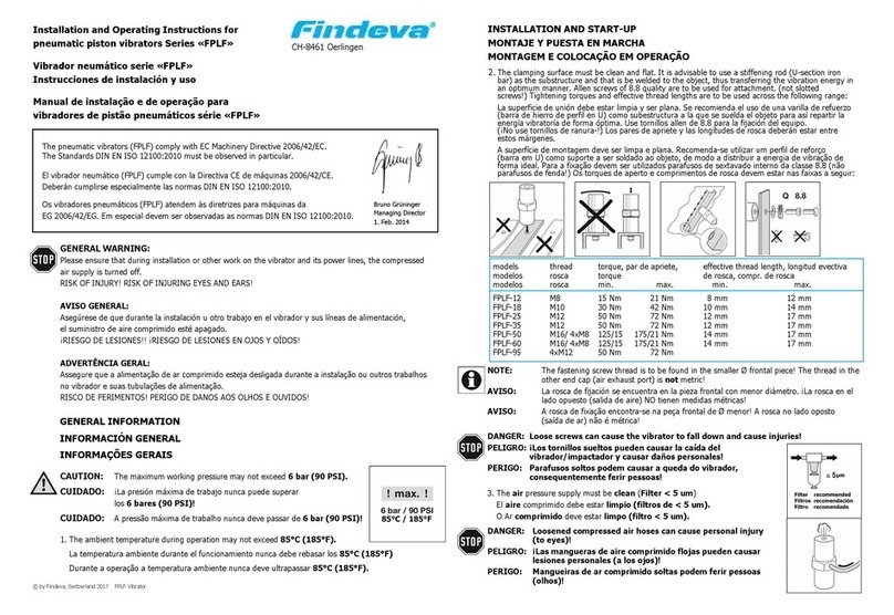
Findeva FKL 200 User manual

--------------------------------------------------- findeva AG
Findeva AG
Loostrasse 2
CH – 8461 Oerlingen
Installation and Short-Form Operating Manual for FKL 100/150/200 si
The pneumatic knockers (FKL) comply with the EC Machinery Directive 98/37/EC. They also comply, in
particular, with Standard EN 292, Parts 1 and 2.
Important Information
FINDEVA AG is unable to accept responsibility whatsoever for damage to property or injury if technical
modifications are made to the product or if the information and instructions in this Operating Manual are not
followed.
Pneumatic vibrators must be installed and operated by an experienced person.
Risk of injury!
• Compressed-air units, such a vibrators, filters, oilers and the air hoses, may be very highly
pressurised. The system must be disconnected from the compressed air supply before such
units are installed or serviced. The units must be depressurised.
• Air pressure may produce extremely loud noise. Consequently, all persons in the surrounding
area of the pneumatic vibrator must wear ear defenders.
• Comply with national and local regulations and regulations governing installation and use of
pneumatic systems.
Noise level
• The noise level of a non-shielded knocker fitted on a metal panel exceeds 85 dB(A), if only the
single noise event is considered. The sustained level is below this, depending on impact
sequence. The noise emitted by the device may be attenuated by sheathings or coverings.
• Noise defenders must be worn in the noise area.
Attachment of the knocker
• Vibrators or knockers and parts of the structure may become detached as the result of
vibration. Screw and nut locking devices must be used.
Lubrication
The FKL 100 pneumatic knocker can be operated with dry compressed air and, thus, unlubricated. If
compressed air containing oil is selected for operation of the knocker, such air must be also be used always
since the basic lubrication of the knocker is flushed out as the result of the air containing oil. The basic version
of the knocker can be operated in a temperature range from –20°C to 80°C. A special version is available for
temperatures between –40°C and 130°C.
Air filter and pressure controller
All compressors feature air filters. However, use an air filter with a particle permeability rating of 5 um. This will
help to prolong the knocker's service life.
FKL Operating Manual
09.08.2002
www.netter-findeva.com

--------------------------------------------------- findeva AG
Compressed air lines
Of course, it is possible to control vibrators by varying the air pressure or air volume. However, please ensure
that the compressed-air units are correctly dimensioned. Quick-release catches are used for connection to the
knocker and to the pneumatic control system.
Knocker
The special feature of this newly developed knocker is broad-band coverage of the impact force adjustment
range and interval adjustment range. This has been made possible by an operating pressure of 2-7.5 bar. The
impact force can be set pneumatically and/or also mechanically. The knocker can thus be used very flexibly.
Pneumatic impact force: by setting the pressure range between 2 and 7 bar. (PTR)
Mechanical impact force control: by fitting and setting the threaded rod with lock nut (remove socket-
head cap screw on the knocker end cap beforehand), it is possible to
restrict the stroke of the piston, thus reducing the impact force. Always
screw in or unscrew the screw with the system depressurised.
mechanical
force control
The knocker is supplied with a base plate used to attach the knocker and transmit the impact force. The
knocker housing and knocker base plate are made of aluminium. The impact plate (integrated in the base plate)
is made of special-purpose impact-resistant plastic.
Field of application
Intermittent compressed-air knockers can be used to dislodge material adhering to container walls (e.g. silos,
hoppers, filter outlets, reactors and pipes).
The knockers can be used in wet areas, in explosion-hazard areas or in the open air.
Mechanical construction and mode of operation
On all intermittent knockers, a piston is forced against a spring by means of compressed air. When quickly
vented, the piston is shot against a surface. On the FKL, this is a baffle plate which is a part of the device.
FKL Operating Manual
09.08.2002

--------------------------------------------------- findeva AG
Operating conditions
Intermittent knockers can be used in dusty environments. The piston seals are suitable for oil-free operation.
Standard installation for Series FKL
1. The control system is the responsibility of the customer
In this case, intermittent control or (ON / OFF) is implemented by the customer by means of a 3/2-way normally
open air valve.
The control function may be performed by
- process control system
- time-lag relay
- switch (on/off)
Maximum distance between valve and FKL 8 m, diameter. 6 mm
2. Pneumatic intermittent control with a PTR (FKL 100 only)
A
The control function can be implemented by an enable signal
from the
-process control system
-time-lag relay
-or another signal
This system has a high impact frequency.
It is also possible to control several units.
FKL Operating Manual
09.08.2002

--------------------------------------------------- findeva AG
Technical Data
Work / Pulse / Air
Impact Impact Weight consumption Cycle
Device bar bar bar Nm Ns kg l/min. impacts/min.
FKL 100 3.5 - 6.0 4.7 - 7.0 4.2 - 7.5 10 - 50 1 - 10.5 4.5 0.5 - 1.1 0.5 - 120
FKL 150 4.5 - 7.0 6.0 - 7.0 7.0 50 - 110 1 - 28.5 9.5 1.2 - 1.7 0.5 - 20
FKL 200 4.2 - 7.5 6.0 - 7.5 7.5 100 - 200 1 - 57.5 14.8 2.2 - 3.3 0.5 - 15
pressure
FKL 100 can be used for wall thicknesses up to 5 mm
FKL 150 can be used for wall thicknesses up to 8 mm
FKL 200 can be used for wall thicknesses up to 12 mm
FKL Operating Manual
09.08.2002

--------------------------------------------------- findeva AG
Dimensions (mm)
mechanical
force control
A1
C1
4 x E1
H
C
A
D
B
E
J
G
mechanical
force control
F
K
KNOCKER A A1 B C C1 D E E1 F G H J K
FKL-100 130 --- 90 100 --- 50 Ø13 --- 302 182 20 55 102
FKL-150 --- Ø140 --- --- Ø115 --- --- Ø13.5 385 272 21 55 110
FKL-200 --- Ø180 --- --- Ø152 --- --- Ø17 410 275 24 55 130
FKL Operating Manual
09.08.2002
www.netter-findeva.com
This manual suits for next models
2
Table of contents
Other Findeva Tools manuals

