Protected by one or more US Patents: 8915613; D702,391; D702,390; D700,732; D727,554 S; D727,550 S, D727,551 S
Note: All power connections to be installed to local/national codes
by a Certified Electrician. Finelite, Inc. • 30500 Whipple Road • Union City, CA 94587-1530 • (510) 441-1100 • Fax: (510) 441-1510 • www.finelite.com 1
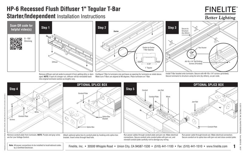
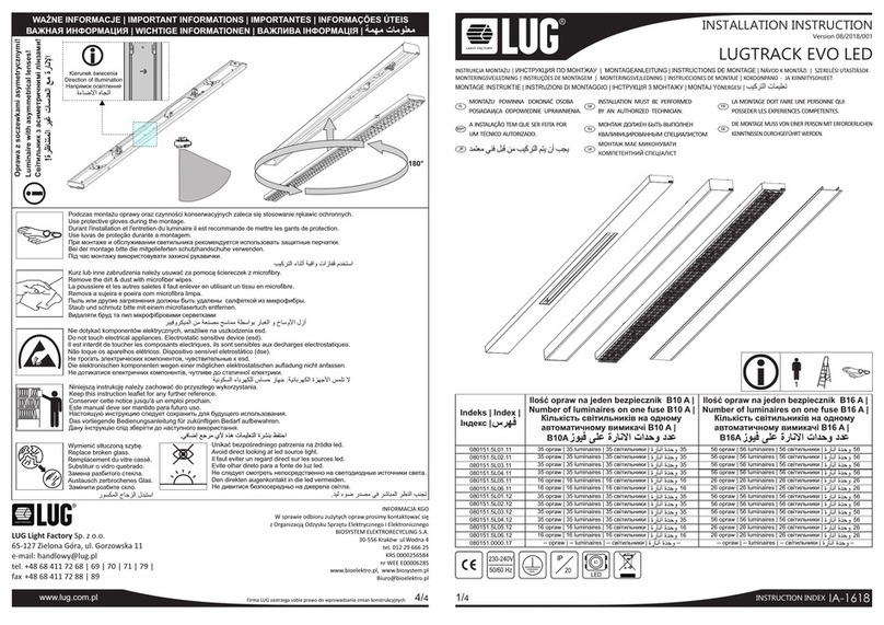
HP-6 Recessed Standard Screw Slot T-Bar
Starter/Independent Installation Instructions
© 2017 FINELITE, INC. ALL RIGHTS RESERVED. Form 98380 V2. 04/17
Step 1 Step 2 Step 3
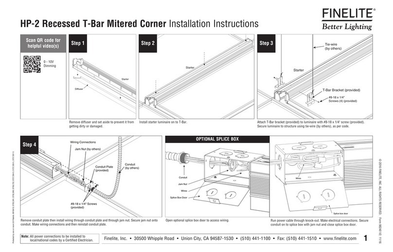
Remove diffuser and set aside to prevent it from getting dirty or
damaged. NOTE: If part of a longer run, diffuser will be reinstalled
back into original luminaire section as lengths vary.
Configure T-Bar to luminaire size and leave an opening for luminaire as noted above.
Make sure T-Bars are aligned at 90 degrees. Place luminaire on T-Bar.
Install T-Bar brackets onto luminaire. Secure with #8-18 x 1/4" screws (provided).
Secure luminaire to structure using tie-wire (by others), as per code.
0 - 10V
Dimming
Scan QR code for
helpful video(s)
Diffuser
Starter
Starter
T-Bar Bracket
Secure to
Structure
(by others)
#8-18 x 1/4" Self Drilling
Screws (4) (Provided)
Step 4 Step 5
Remove conduit plate from luminaire. NOTE: Purple and gray wires
are for Low Voltage Control.
Run power cables through conduit plate and jam nut. Make electrical
connections. Secure conduit onto conduit plate with jam nut, and
reinstall conduit plate carefully not to damage any wiring.
Attach optional splice box to conduit plate by hooking onto splice box
bracket. Insert wires through feed hole.
Splice Box
Conduit Plate
Splice Box
Bracket
Conduit
Conduit Plate
Jam Nut
Wires
Wires
Conduit Plate
Jam Nut
Conduit Plate
Run power cable through knock-out. Make electrical connection.
Secure conduit on to splice box with jam nut and close conduit plate.
Screws
OPTIONAL SPLICE BOX OPTIONAL SPLICE BOX
Center-to-Center
T-Bar Spacing
Standard Screw Slot
