Flex S 703 BVE User manual

S 703 BVE
Instruction manual
Bedienungsanleitung
Manual de instrucciones
Manuel d’utilisation
Gebruikshandleiding
Bruksanvisning
Manuale delle istruzioni
Copyright © 2002 Porter-Cable Corporation
259.921

D-71711 Steinheim/Murr – Tel. (0 71 44) 8 28-0 – Fax (0 71 44) 2 58 99

Figures, Abbildungen, Figuras, Figures, Afbeeldingen, Figurer, Figure
1 2
34
A
B
5
A
B
C
6
A
B

Figures, Abbildungen, Figuras, Figures, Afbeeldingen, Figurer, Figure
9
A
78
10
11 12
A
A

1
ADDITIONAL SAFETY RULES FOR PORTABLE BAYONET SAWS
1. KEEP BLADES SHARP.
2. KEEP HANDS AWAY FROM CUTTING AREA. When sawing never reach underneath or behind the
material being cut for any reason.
3. WHEN YOU HAVE FINISHED A CUT be careful not to come into contact with the blade. Turn off the
motor immediately.
4. WARNING: EXERCISE EXTREME CAUTION WHEN BLIND CUTTING TO BE CERTAIN THAT
THERE ARE NO FOREIGN OBJECTS SUCH AS ELECTRICAL WIRE, CONDUIT, PLUMBING PIPES, ETC.,
THAT MAY COME INTO CONTACT WITH THE BLADE.
5. SOME WOOD CONTAINS PRESERVATIVES WHICH CAN BE TOXIC. Take extra care to prevent
inhalation and skin contact when working with these materials. Request, and follow, any safety
information available from your material supplier.
REPLACEMENT PARTS
When servicing use only identical replacement parts.
ASSEMBLY
ANTI-SPLINTER BASE INSERT INSTALLATION
The anti-splinter base insert is used to reduce chipping and splintering of the top fibers of plywood,
paneling, and other splinter prone materials. When this insert is used it is not necessary to have the
good or finished side of the work down during the cutting operation.
Install the insert as shown in figure 1. NOTE: When using the anti-splinter insert, the base should be set
to the forward-most position, Fig. 9.
ANTI-MAR PLASTIC SUB-BASE INSTALLATION
CAUTION: DISCONNECT TOOL FROM POWER SOURCE.
The anti-mar plastic sub-base is used when cutting on finished surfaces to prevent the normal metal
base from scratching, gouging, or otherwise marring the surface of the material to be cut.
To install the plastic sub-base, remove the six screws from the bottom of the base, remove the metal
sub-base, place the plastic sub-base on the saw, and reinstall the six screws. Be sure to save the metal
sub-base for reuse.
BLADE INSTALLATION
1. Open front guard A, Fig. 12.
2. Remove anti-splinter insert if installed.
3. Gently squeeze the switch trigger until the blade shaft moves slowly and stop the motor when the
blade shaft is at or near the bottom of its stroke, Fig. 6.
CAUTION: DISCONNECT TOOL FROM POWER SOURCE.
TECHNICAL SPECIFICATIONS
Voltage supply....................................... 230 V A – weighted noise level
Power consumption.............................. 705 W Sound pressure level............................ 84 dB
Power output........................................ 460 W Sound power level................................ 97 dB
Frequency ......................................... 50/60 Hz
WEAR EAR PROTECTION!
Strokes per minute (max.)............... 500-3100 Typical Mean effective Acceleration.......... 5 m/s2
Stroke............................................... 25.4 mm Weight
Max. cutting depth (steel).................... 20 mm Without case and accessories ............. 3.0 kg

2
4. Open the blade clamp by rotating the movable lever (B), Fig. 2, towards the stationary lever (A), Fig.
2 as far as it will go and hold.
5. While holding the blade clamp open: move lever (A) as far forward as it will go, (See Figs. 2 & 3),
and hold.
NOTE: Steps 4 and 5 should be done in one motion.
6. With the teeth of the blade toward the front of the saw, insert the blade through the blade guide into
the blade holder as far as it will go and release the levers. See figure 4.
7. Pull up on the blade until it locks in place. The blade is properly installed when the levers are aligned
as shown in figure 4.
8. Close front guard A, Fig. 12.
BLADE REMOVAL
1. Open front guard A, Fig. 12.
2. Remove the anti-splinter insert if installed.
3. Gently squeeze the switch trigger until the blade shaft moves slowly and stop the motor when the
blade shaft is at or near the bottom of its stroke, Fig. 6.
CAUTION: DISCONNECT TOOL FROM POWER SOURCE.
4. Open the blade clamp by rotating the movable lever (B), Fig. 2, towards the stationary lever (A), Fig.
2, as far as it will go.
5. Move the blade shaft forward until the blade is clear of the blade guide.
6. Grasp the tip of the blade, move it towards the blade holder lever/right hand side of saw and pull the
blade out of the clamp.
7. Close front guard A, Fig. 12.
OPERATION
TO START AND STOP SAW
Make sure power circuit voltage is the same as shown on the specification plate on the saw, and that
saw switch is OFF. Connect saw to power circuit.
1. Squeeze trigger switch (A), Fig. 5, to start motor. Release trigger to stop motor.
2. Lock Button – A lock button (B), Fig. 5, is provided to keep the saw running without holding the
switch trigger “ON”. To lock the switch trigger “ON”, squeeze the trigger as far as it will go and push in
the lock button and release trigger.
To UNLOCK the lock, squeeze trigger allowing lock button to spring out, and release trigger.
VARIABLE SPEED
This saw is equipped with an adjustable variable speed control and the speed range is 500 to 3100
SPM. The speed is adjusted by turning the control knob (C), Fig. 5. The speed control may be adjusted
with or without the motor running.
Use higher speed settings for fast cutting when finish and accuracy are not critical. Use slower speed
settings when accuracy and finish are critical or for delicate materials.
BLADE ORBIT
The blade orbit may be varied by turning knob (A), Fig. 6, to any of four positions indicated by the
numbers “0” through “3”, with “0” producing no orbit and “3” producing maximum orbit. The orbit may
be adjusted with or without the motor running. Move knob (A), Fig. 6, to the detent in the housing
corresponding to the number on the housing. The knob is shown in position “0”. The straight up and
down position would be setting “3”. Metal cutting should be performed in orbit setting “0”.
Use of higher orbit settings when performing intricate scroll cuts may cause blade breakage. The lower
orbit settings are recommended for scrolling. Orbit position “0” will produce the most accurate cuts
with less splintering and the longest blade life.

3
CHIP BLOWER
This saw is equipped with a chip blower to keep the cutting area free of chips. Use knob (B), Fig. 6, to
turn the chip blower on and off. The knob is shown in the off position, to turn the chip blower on, turn the
knob counterclockwise until it stops.
PLUNGE CUTTING
WARNING: When cutting into a wall, avoid contact with all exposed metal on the tool to
prevent electrical shock hazard resulting from accidentally cutting into a live wire. HOLD
SAW AS ILLUSTRATED IN FIG. 7.
One of the distinctive and important features of the FLEX bayonet saw is the ability to start the cut (in
wood only) within an area without making drilled holes first. This is especially important when making
cutouts for electrical outlets in finished walls, openings in cabinet tops for sinks and openings for
plumbing fixtures.
NOTE: When plunge cutting, it is recommended the orbit knob be set to position “3”.
First, measure the area to be cut out and mark it clearly with a pencil chalk or scriber. Choose a
convenient starting point and hold the bayonet saw over the point and inside the line of waste. Tip the
machine forward until the front edge of the base rests firmly on the surface of the material with the tip of
the blade clear of the work surface, as shown in Fig. 8. Turn motor “on” and slowly lower the back of the
machine until the base is fully seated on the surface of the work. Now, guide the cutting along the inside
of the marked area. If sharp corners are desired, cut right up to the corner of the marked edge. Stop and
back up just a bit, start the turn and cut along the side. Do the same at each corner until you end up
where you started. Then, go back and cut into each corner from the opposite direction. The base of the
machine is wide enough so you will have a solid guiding surface on either side of the cut.
BASE ADJUSTMENT
The base may be adjusted two ways, front to rear and tilted either left or right for making bevel cuts. The
base has a detent at the 0 (90 degree) setting and at 15, 30 and 45 degree setting both left and right of
center.
The base is set at its forward-most position at the factory. The base can be adjusted to the rear for
making flush cuts around walls and other similar areas. To move the base forward or backward, turn the
saw on its side, loosen screw (A), Fig. 9, move the base to the desired position and retighten the screw.
NOTE: When making bevel cuts, the base should be set to the forward most position, Fig. 9.
To tilt the base, pull the lever out of the end of clamp screw (A), Fig. 10, rotate the lever toward the front
of the saw, Fig. 11, and turn the lever counterclockwise until the base can be tilted. Set the base at the
desired setting and tighten the screw by turning the lever clockwise.
NOTE: After each 90 degree or half turn, it will be necessary to move the lever back to the
opposite side of the saw.
USING THE SAW
First, secure the material in a bench vise or with clamps to the work table. This is especially important
when sawing small pieces or thin material. As the work progresses in scroll or curved cut-out pieces,
the material can be readjusted to accommodate the movement of the saw. If the work is large enough it
can be held by hand across saw horses. The saw cuts freely with only light forward feed pressure on the
tool. Forcing the saw will not make it cut faster.
To start the cut, secure the work, mark the line of cut clearly, place the forward edge of the saw base
firmly on the edge of the material, start the motor and move the blade into the work.
DO NOT FORCE, LET THE SAW DO THE WORK. Move the machine forward only rapidly enough to keep
the blade cutting.
You will find that the open throat and clear forward edge of the saw base make it easy to follow the line
and cut closely to the pattern. You need not cut oversize for hand finishing or sanding on most
materials. The smoothness of cut will often make further sanding unnecessary.

4
MAINTENANCE
KEEP TOOL CLEAN
Periodically blow out all air passages with dry, compressed air. All plastic parts should be
cleaned with soft damp cloth. NEVER use solvents to clean plastic parts. They could
possibly dissolve or otherwise damage the material.
CAUTION: Wear safety glasses while using compressed air.
FAILURE TO START
Should your tool fail to start, check to make sure the prongs on the cord plug are making
good contact in the outlet. Also, check for blown fuses or open circuit breakers in the line.
LUBRICATION
This tool has been lubricated with a sufficient amount of high grade lubricant for the life of
the unit under normal operating conditions. No further lubricant is necessary.
BRUSH INSPECTION AND LUBRICATION
For your continued safety and electrical protection, brush inspection and replacement on
this tool should ONLY be performed by an Authorized Service Agent for FLEX Power Tools.
At approximately 100 hours of use, take or send your tool to your nearest Authorized
Service Agent for FLEX Power Tools to be thoroughly cleaned and inspected; worn parts
replaced, and when necessary; relubricated with fresh lubricant, if required; reassembled
with new brushes; and performance tested.
Any loss of power before the above maintenance check may indicate the need for
immediate servicing of your tool. DO NOT CONTINUE TO OPERATE TOOL UNDER THIS
CONDITION. If proper operating voltage is present, return your tool to the Service Agent for
immediate service.
SERVICE AND REPAIRS
All quality tools will eventually require servicing or replacement of parts due to wear from
normal use. These operations, including brush inspection and replacement, should ONLY be
performed by an AUTHORIZED Service Agent for FLEX Power Tools. All repairs made by these
agencies are fully guaranteed against defective material and workmanship. We cannot
guarantee repairs made or attempted by anyone other than these agencies.
Should you have any questions about your tool, feel free to write us at any time. In any
communications, please give all information shown on the nameplate of your tool (model
number, type, serial number, etc.).

1
ZUSÄTZLICHE SICHERHEITSHINWEISE FÜR TRAGBARE BAJONETT-STICHSÄGEN
1. NUR SCHARFE SÄGEBLÄTTER VERWENDEN!
2. DIE HÄNDE VOM ARBEITSBEREICH FERNHALTEN! Beim Sägen dürfen Sie niemals mit den Händen
unter oder hinter dem zu schneidenen Material greifen, egal aus welchem Grund.
3. WENN EIN SCHNITT ZU ENDE IST, achten Sie darauf, daß Sie nicht mit dem Sägeblatt in Berührung
kommen. Den Motor sofort ausschalten!
4. ACHTUNG: BEI BLINDSCHNITTEN SEIEN SIE ÄUSSERST VORSICHTIG, DASS KEINE STROM-
LEITUNGEN, ROHRE, WASSERLEITUNGEN USW. MIT DEM SÄGEBLATT IN BERÜHRUNG KOMMEN.
5. EINIGE HOLZARTEN ENTHALTEN GESUNDHEITSGEFÄHRDENDE SCHUTZMITTEL. Beim Arbeiten
mit solchen Werkstoffen sind besondere Vorsichtsmaßnahmen zu treffen, damit der Werkstoff nicht
eingeatmet wird oder in Berührung mit der Haut kommt. Die Sicherheitshinweise des Lieferanten sind
anzufordern und strikt zu befolgen.
ERSATZTEILE
Bei Wartungs- bzw. Reparaturarbeiten nur Originalersatzteile verwenden!
ZUSAMMENBAU
EINBAU DES SPANNREISSCHUTZ-FUSSEINSATZES
Mit dem Spannreißschutz-Fußeinsatz werden das Absplittern und das Ausreißen der oberen Holzfasern
von Sperrholz, Paneelen und anderen Materialien, die zum Zersplittern neigen, reduziert. Beim Verwenden
dieses Einsatzes ist es nicht notwendig, daß die gute oder schon bearbeitete Seite des Werkstückes
während des Schneidvorgangs nach unten gerichtet ist.
Der Fußeinsatz wird so eingebaut, wie in Abb. 1 gezeigt wird. HINWEIS: Beim Verwenden des
Spannreißschutz-Fußeinsatzes sollte die Fußplatte in die vorderste Position versetzt werden, wie in Abb. 9
gezeigt wird.
EINBAU DES OBERFLÄCHENSCHÜTZENDEN KUNSTSTOFFUNTERTEILS
DER FUSSPLATTE
VORSICHT: DEN NETZSTECKER DER STICHSÄGE AUS DEM NETZANSCHLUSS ZIEHEN!
Beim Schneiden von schon bearbeiteten Flächen wird der oberflächenschützende Kunststoffunterteil an die
Fußplatte anmontiert, um das Kratzen, das Aushöhlen oder das sonstige Beschädigen des zu
schneidenden Materials durch die Standard-Metallfußplatte zu verhindern.
Zum Einbau des Kunststoffunterteils der Fußplatte schrauben Sie die sechs Schrauben aus der Unterseite
der Fußplatte heraus, nehmen Sie den Metallunterteil der Fußplatte ab, setzen Sie den Kunststoffunterteil
der Fußplatte auf die Säge auf und schrauben Sie die sechs Schrauben wieder ein. Dabei achten Sie darauf,
daß der Metallunterteil der Fußplatte zur Wiederverwendung sicher aufbewahrt wird.
EINSATZ DES SÄGEBLATTES
1. Den in Abb. 12 gezeigten vorderen Schutzbügel A öffnen.
2. Den Spannreißschutz-Fußeinsatz abnehmen, wenn er schon eingebaut ist.
3. Die Schalttaste leicht drücken, bis der Schaft des Sägeblattes sich langsam bewegt. Den Motor
ausschalten, wenn der Schaft des Sägeblattes die untere Position seines Hubes erreicht oder sich der
unteren Position seines Hubes nähert, wie in Abb. 6 gezeigt wird.
VORSICHT: DEN NETZSTECKER DER STICHSÄGE AUS DEM NETZANSCHLUSS ZIEHEN!
4. Zum Öffnen der Sägeblatthalterung den in Abb. 2 gezeigten beweglichen Hebel (B) in Richtung des in
Abb. 2 gezeigten unbeweglichen Hebel (A) soweit wie möglich drehen und in dieser Stellung festhalten.
GERÄTEKENNWERTE
Netzspannung ....................................... 230 V A – bewerteter Geräuschpegel
Aufnahmeleistung ................................ 705 W Schalldruckpegel ...................................... 84 dB
Abgabeleistung .................................... 460 W Schalleistungspegel ................................... 97 dB
Frequenz ........................................... 50/60 Hz
GEHÖRSCHUTZ TRAGEN!
Hubzahl pro Minute (max.) ............. 500-3100 Typischer mittlerer Effektiv-
Hubweg ............................................ 25,4 mm Beschleunigungswert ................................ 5 m/s2
Max. Schnittiefe (Stahl) ...................... 20 mm Gewicht
Ohne Koffer und Zubehör .......................................... 3,0 kg

2
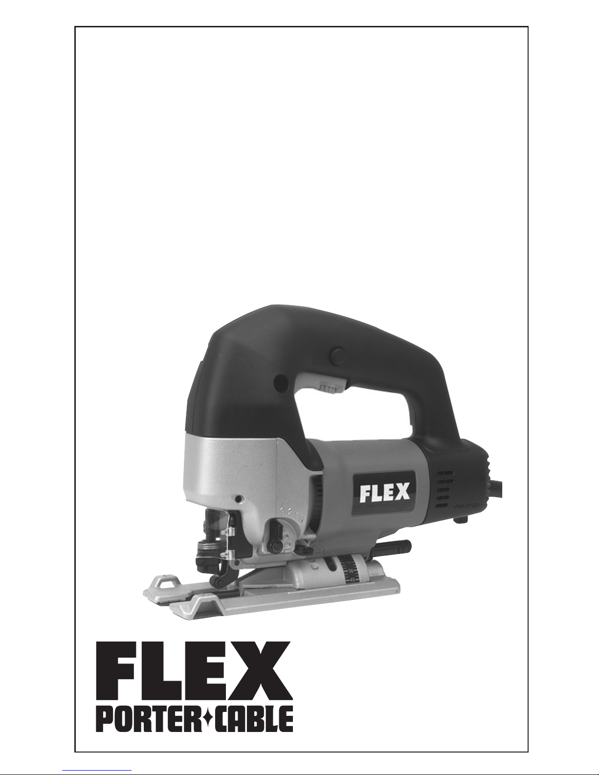
5. Während die Sägeblatthalterung in der geöffneten Stellung gehalten wird, den Hebel (A) soweit wie
möglich nach vorn bringen (siehe Abb. 2 und Abb. 3) und in dieser Stellung halten.
HINWEIS: Die Schritte 4 und 5 sollten in einer einzigen Bewegung ausgeführt werden.
6. Die Sägeblattzahnung in Schnittrichtung richten, das Sägeblatt durch die Sägeblattführung in die
Sägeblatthalterung bis zum Anschlag einstecken, dann die beiden Hebel loslassen. Siehe Abb. 4.
7. Das Sägeblatt unter leichtem Zug einrasten lassen. Das Sägeblatt ist sachgemäß eingesetzt, wenn die
beiden Hebel so ausgerichtet sind, wie in Abb. 4 gezeigt wird.
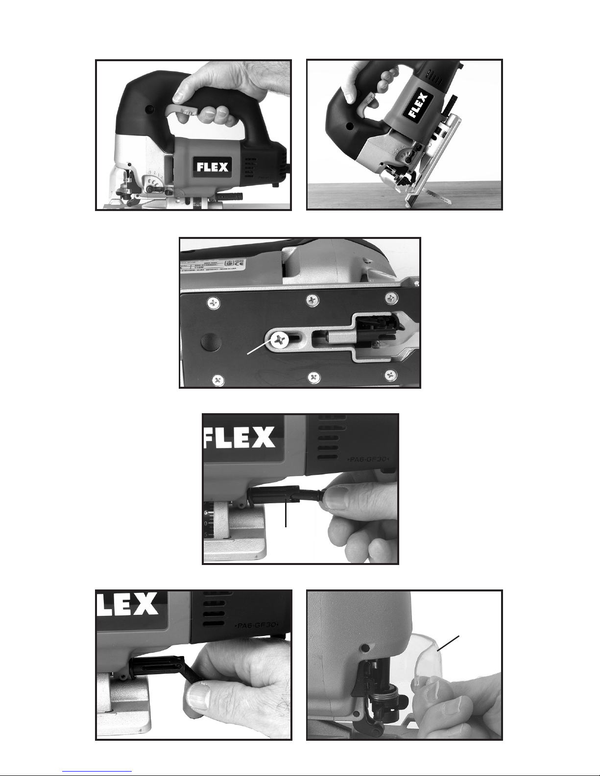
8. Den in Abb. 12 gezeigten vorderen Schutzbügel A schließen.
HERAUSNEHMEN DES SÄGEBLATTES
1. Den in Abb. 12 gezeigten vorderen Schutzbügel A öffnen.
2. Den Spannreißschutz-Fußeinsatz abnehmen, wenn er schon eingebaut ist.
3. Die Schalttaste leicht drücken, bis der Schaft des Sägeblattes sich langsam bewegt. Den Motor
ausschalten, wenn der Schaft des Sägeblattes die untere Position seines Hubes erreicht oder sich der
unteren Position seines Hubes nähert, wie in Abb. 6 gezeigt wird.
VORSICHT: DEN NETZSTECKER DER STICHSÄGE AUS DEM NETZANSCHLUSS ZIEHEN!
4. Zum Öffnen der Sägeblatthalterung den in Abb. 2 gezeigten beweglichen Hebel (B) in Richtung des in
Abb. 2 gezeigten unbeweglichen Hebel (A) soweit wie möglich drehen.
5. Den Sägeblattschaft nach vorn bringen, bis das Sägeblatt von der Sägeblattführung frei ist.
6. Die Sägeblattspitze anfassen und in Richtung des Hebels der Sägeblatthalterung bzw. nach der rechten
Seite der Stichsäge bringen. Dann das Sägeblatt aus der Halterung herausziehen.
7. Den in Abb. 12 gezeigten vorderen Schutzbügel A schließen.
INBETRIEBNAHME
EINSCHALTEN UND AUSSCHALTEN DER STICHSÄGE
Darauf achten, daß die Spannung der Stromquelle mit der auf dem Typenschild der Stichsäge angezeigten
Spannung übereinstimmt sowie daß die Schalttaste in “AUS”-Position ist. Den Netzstecker der Stichsäge
in die Steckdose einstecken.
1. Zum Einschalten des Motors die in Abb. 5 gezeigte Schalttaste (A) drücken. Zum Ausschalten des
Motors die Schalttaste loslassen.
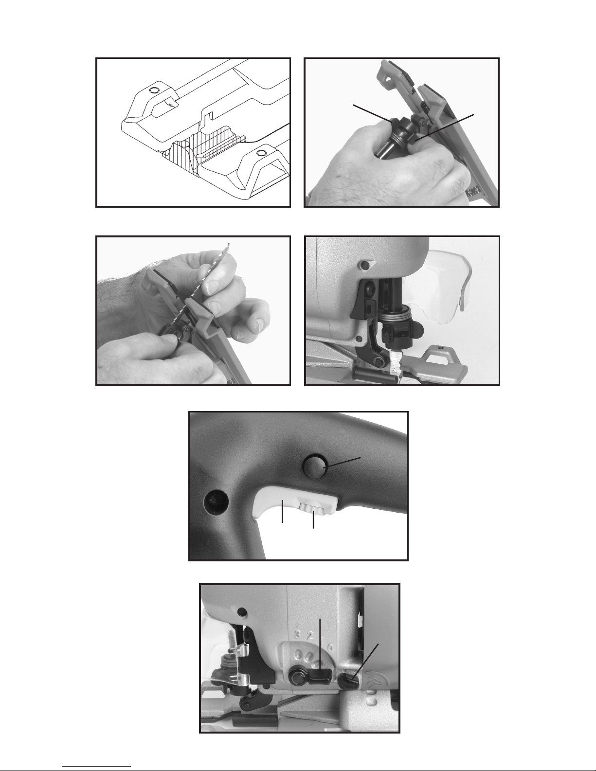
2. Arretierknopf – Mit dem in Abb. 5 gezeigten Arretierknopf (B) ist es möglich, die Stichsäge laufen zu
lassen, ohne daß die Schalttaste in “EIN”-Position gehalten werden muß. Zur Betätigung der
Dauereinschaltung die Schalttaste soweit wie möglich drücken, dann auf den Arretierknopf drücken und
die Schalttaste loslassen.
Zum AUFHEBEN der Dauereinschaltung die Schalttaste drücken. Dadurch springt der Arretierknopf wieder
raus. Dann die Schalttaste wieder loslassen.
STUFENLOSE HUBZAHL
Diese Stichsäge ist mit einer stufenlosen Hubzahlregulierung ausgestattet, die eine Hubzahl zwischen 500
und 3,100 Hub pro Minute ermöglicht. Die Hubzahl wird durch Drehen des in Abb. 5 gezeigten
Stellknopfes (C) eingestellt. Die Hubzahl kann sowohl beim laufenden als auch beim stillstehenden Motor
eingestellt werden.
Eine höhere Hubzahl wird bei hoher Schnittleistung eingestellt, wenn das Aussehen der Oberfläche und die
Genauigkeit des Schnittes nicht so kritisch sind. Eine kleinere Hubzahl wird beim Schneiden von
empfindlichen Materialien eingestellt, wenn die Genauigkeit des Schnittes und das Aussehen der
Oberfläche kritisch sind.
PENDELUNG DES SÄGEBLATTES
Durch Drehen des in Abb. 6 gezeigten Stellknopfes (A) kann die Pendelung des Sägeblattes nach Wunsch
eingestellt werden. Zur Wahl stehen vier Pendelhubstufen, die mit den Zahlen “0” bis “3” gekennzeichnet
sind. Die Zahl “0” bedeutet keine Pendelung und die Zahl “3” bedeutet maximale Pendelung. Die
Pendelung kann sowohl beim laufenden als auch beim stillstehenden Motor eingestellt werden. Der in Abb.
6 gezeigte Stellknopf (A) wird soweit gedreht, bis er die Arretierung im Gehäuse erreicht, die der Zahl am
Gehäuse entspricht. Gezeigt wird der Stellknopf in der Stellung “0”. Die vertikale Stellung des Stellknopfes
würde der Stellung “3” entsprechen. Beim Metallschneiden sollte die Pendelhubstufe “0” verwendet
werden.

3
Bei hochanspruchsvollen Laubschnitten kann eine höhere Pendelhubstufe zum Bruch des Sägeblattes
führen. Für solche Laubschnitte sind kleinere Pendelhubstufen zu empfehlen. Mit der Pendelhubstufe “0”
werden die präzisesten Schnitte erzielt, wobei der Spannausreiß vermindert wird und die Standzeit des
Blattes erhöht wird.
BLASVORRICHTUNG ZUR BESEITIGUNG VON SPÄNEN
Diese Stichsäge ist mit einer Blasvorrichtung ausgestattet, die durch Wegblasen von Spänen die Sicht auf
die Schnittstelle freihält. Durch den in Abb. 6 gezeigten Knopf (B) wird die Blasvorrichtung ein- und
ausgeschaltet. Gezeigt wird der Knopf in der ausgeschalteten Position. Zum Einschalten der
Blasvorrichtung drehen Sie den Knopf nach links bis zum Anschlag.
TAUCHSCHNITTE
ACHTUNG: Bei Wandausschnitten achten Sie darauf, daß Sie mit keinen metallischen Teilen der
Maschine in Kontakt stehen. Sonst besteht die Gefahr eines elektrischen Schlages durch das
Ansägen einer spannungsführenden Leitung. DIE STICHSÄGE SO HALTEN, WIE IN ABB. 7
GEZEIGT WIRD.
Ein besonderes und wichtiges Merkmal der Bajonett-Stichsäge von FLEX ist die Fähigkeit, einen
Tauchschnitt (nur in Holz) zu machen, ohne daß es notwendig ist, im Bereich des Tauchschnittes
vorzubohren. Dies ist besonders wichtig beim Sägen von Löchern in fertiggestellten Wände, um
elektrische Anschlüße zu installieren, beim Einbau von Spülbecken in beispielsweise Küchenschränke
sowie beim Sägen von Löchern, um Rohre und Wasserleitungen zu legen.
HINWEIS: Bei Tauchschnitten ist es empfohlen, den Pendelhubstufenknopf auf Stellung “3”
einzustellen.
Zuerst sollen Sie den Bereich, der auszuschneiden ist, ausmessen und mit Bleistift, Kreide oder Reißahle
deutlich anzeichnen. Dann wählen Sie einen geeigneten Ausgangspunkt und halten Sie die Bajonett-
Stichsäge über diesem Punkt und innerhalb der Anrißlinie. Kippen Sie die Maschine nach vorn, bis die
vordere Kante der Fußplatte einen festen Sitz auf der Oberfläche des Materials hat, wobei die Spitze des
Sägeblattes die Arbeitsfläche noch nicht berühren darf, wie in Abb. 8 gezeigt wird. Schalten Sie den Motor
ein und lassen Sie den hinteren Teil der Maschine langsam auf die Oberfläche herab, bis die ganze
Fußplatte auf der Arbeitsfläche liegt. Nun sägen Sie entlang, aber innerhalb der Anrißlinie. Sollten Sie
rechtwinklige Ecken erwünschen, schneiden Sie entlang der Anrißlinie bis zur Ecke der angezeichneten
Linie. Halten Sie an, ziehen Sie die Maschine etwas zurück, schneiden Sie die Kurve aus, dann schneiden
Sie die nächste Seite aus. Wiederholen Sie diesen Vorgang so lange, bis der Ausgangspunkt wieder
erreicht ist. Dann schneiden Sie jede Ecke von der entgegengesetzten Richtung an. Die Fußplatte der
Maschine is breit genug, um auf der einen oder anderen Seite des Schnittes einen festen Sitz zu gewähren.
EINSTELLUNG DER FUSSPLATTE
Die Fußplatte kann auf zweierlei Art verstellt werden. Sie kann von vorn nach hinten versetzt werden und
für Schrägschnitte nach links oder nach rechts geschwenkt werden. Die Fußplatte weist eine Arretierung
für die Stellung 0 (90 Grad) sowie auf beiden Seiten der Null-Stellung Arretierungen für Stellungen, die 15,
30 und 45 Grad entsprechen.
Die Fußplatte wird in der Fabrik in die vorderste Position versetzt. Für das randnahe Sägen entlang Wänden
oder ähnlichen Bereichen kann die Fußplatte nach hinten versetzt werden. Zum Versetzen der Fußplatte
nach hinten bzw. nach vorn geht man wie folgt vor: Die Stichsäge auf die Seite legen, die in Abb. 9 gezeigte
Schraube (A) lösen, die Fußplatte in die gewünschte Position bringen und die Schraube wieder festziehen.
HINWEIS: Bei Gehrungsschnitten sollte die Fußplatte in die vorderste Position versetzt werden
(siehe Abb. 9).
Zum Schwenken der Fußplatte geht man wie folgt vor: Den Hebel aus dem Ende der in Abb. 10 gezeigten
Spannschraube (A) herausziehen, den Hebel in Schnittrichtung drehen, wie in Abb. 11 gezeigt wird, dann
den Hebel nach links drehen, bis die Fußplatte geschwenkt werden kann. Die Fußplatte in die gewünschte
Stellung einstellen und die Schraube durch Rechtsdrehen des Hebels festziehen.
HINWEIS: Nach jeder 90°-Drehung bzw. halber Drehung, wird es notwendig werden, den Hebel
an die entgegengesetzte Seite der Stichsäge zurück zu bringen.
DIE VERWENDUNG DER STICHSÄGE
Das Material sollte zuerst in einen Schraubstock geklemmt werden oder mit Schraubzwingen an der
Werkbank befestigt sein. Besonders wichtig ist dieser Vorgang beim Schneiden von kleineren Teilen oder
dünnem Material. Bei Laub- und Kurvenschnitten können Werkstücke entsprechend dem Arbeitsfortschritt
gegebenenfalls neu eingespannt werden. Größere Werkstücke können mit der Hand auf Sägeblöcken
gehalten werden. Die optimale Schnittgeschwindigkeit wird mit geringem Vorschubdruck erreicht. Starker
Druck erhöht die Schnittgeschwindigkeit nicht.

4
Um den Schnitt anzufangen, befestigen Sie das Werkstück und zeichnen Sie deutlich die Anrißlinie an,
dann bringen Sie die vordere Kante der Fußplatte der Säge auf den Rand des Materials, schalten Sie den
Motor ein und bewegen Sie das Sägeblatt auf das Werkstück zu.
STARKER DRUCK DARF NICHT AUSGEÜBT WERDEN. DIE STICHSÄGE SOLLTE SELBST DIE ARBEIT
LEISTEN. Bewegen Sie die Stichsäge nur so schnell nach vorn, daß das Sägeblatt weiter schneidet.
Sie werden herausfinden, daß der offene Hals sowie die übersichtliche vordere Kante der Fußplatte der
Stichsäge es erleichtert, der Anrißlinie zu folgen und das Muster exakt auszuschneiden. Für die meisten
Materialien ist es nicht notwendig, zuerst einen groben Schnitt zu machen und danach das Werkstück von
Hand zu bearbeiten bzw. zu schleifen. Oft ist der Schnitt so glatt, daß ein zusätzliches Schleifen erübrigt
wird.
WARTUNG
DAS WERKZEUG SAUBERHALTEN!
Kühlöffnungen regelmäßig mit Druckluft ausblasen. Kunststoffteile sollten mit einem sauberen, feuchten
Tuch gereinigt werden. Lösungsmittel NIEMALS zum Reinigen von Kunststoffteilen verwenden, da diese
Teile eventuell dadurch aufgelöst oder beschädigt werden können.
VORSICHT! Beim Verwenden von Druckluft Schutzbrille tragen!
DIE MASCHINE KANN NICHT EINGESCHALTET WERDEN
Sollte es nicht möglich sein, die Maschine einzuschalten, prüfen Sie, ob die Zinken des Netzstekkers in
gutem Kontakt mit der Steckdose sind. Es sollte auch geprüft werden, ob Leitungsschutzsicherungen
durchgeschmolzen oder Leitungsschutzschalter geöffnet sind.
SCHMIEREN
Diese Maschine wurde mit hochwertigem Schmiermittel in einer Menge, die unter normalen Betriebsbe-
dingungen für das Leben des Werkzeuges ausreichend ist, geschmiert. Weiteres Schmieren ist nicht
notwendig.
PRÜFEN DER KOHLEBÜRSTEN UND SCHMIEREN
Zu Ihrer Sicherheit und um Schutz gegen einen elektrischen Schlag zu gewähren, sollte das Prüfen und
Auswechseln der Kohlebürsten NUR von einer autorisierten Kundendienststelle für FLEX-
Elektrowerkzeuge vorgenommen werden.
Nach ungefähr 100 Betriebsstunden sollte das Werkzeug der nächstgelegenen autorisierten
Kundendienststelle für FLEX-Elektrowerkzeuge zur gründlichen Reinigung und Inspektion gebracht oder
geschickt werden. Gegebenenfalls sollten Verschleißteile ausgewechselt werden. Falls notwendig, sollte
das Werkzeug neu geölt und mit neuen Kohlebürsten ausgerüstet werden. Danach sollte die Leistung des
Werkzeuges geprüft werden.
Sollte das Werkzeug bevor der obenerwähnten Inspektion ausfallen, sind sofortige Wartungs- bzw.
Reparaturarbeiten möglicherweise notwendig. IN DIESEM FALL DAS WERKZEUG NICHT WEITER
BETREIBEN! Nachdem Sie die Netzspannung kontrolliert haben, bitte Ihr Werkzeug sobald wie möglich
der Kundendienststelle übergeben.
SERVICE UND REPARATUREN
Alle Qualitätswerkzeuge unterliegen bei normaler Benutzung Verschleiß. Deswegen müssen sie von Zeit zu
Zeit gewartet werden und vorhandene Verschleißteile müssen ausgewechselt werden. Dazu gehören
Inspektion und Auswechslung der Kohlebürste. Diese Arbeiten dürfen NUR von einer AUTORISIERTEN
Kundendienststelle für FLEX Elektrowerkzeuge unternommen werden. Hierbei haben Sie die volle Garantie
für Material und Leistung. Reparaturen, die nicht von den obenerwähnten Vertretungen gemacht oder
unternommen worden sind, sind von der Garantieleistung ausgeschlossen.
Sollten Sie Fragen zu Ihrem Werkzeug haben, bitte schreiben Sie uns zu jeder Zeit. Dabei die Angaben auf
dem Typenschild des Werkzeugs (Modell-Nummer, Typ, Fabrikationsnummer usw.) angeben.

1
NORMAS DE SEGURIDAD ADICIONALES PARA SIERRAS DE BAYONETA
PORTÁTILES
1. MANTENGA AFILADAS LAS HOJAS.
2. MANTENGA LAS MANOS ALEJADAS DE LA ZONA DE CORTE. Al aserrar, nunca ponga las manos
por ningún motivo debajo o detrás del material que se esté cortando.
3. CUANDO HAYA ACABADO UN CORTE, tenga cuidado de no entrar en contacto con la hoja. Apague
el motor inmediatamente.
4. ADVERTENCIA: TENGA SUMO CUIDADO AL CORTAR EN ZONAS CIEGAS PARA ASEGURARSE
DE QUE NO HAYA OBJETOS EXTRAÑOS, COMO CABLES ELÉCTRICOS, CONDUCTOS, TUBERÍAS DE
FONTANERÍA, ETC., QUE PUEDAN ENTRAR EN CONTACTO CON LA HOJA.
5. ALGUNAS MADERAS CONTIENEN CONSERVANTES QUE PUEDEN SER TÓXICOS. Tenga cuidado
adicional para evitar la aspiración y el contacto con la piel al trabajar con estos materiales. Solicite y siga
toda la información de seguridad de que disponga el proveedor del material.
PIEZAS DE REPUESTO
Al hacer servicio de la herramienta, utilice únicamente piezas de repuesto idénticas.
MONTAJE
INSTALACIÓN DEL ACCESORIO DE INSERCIÓN ANTIASTILLAS DE LA BASE
El accesorio de inserción antiastillas de la base se utiliza para reducir el descascaramiento y astillamiento
de las fibras superiores de la madera contrachapada, los paneles y otros materiales propensos a
astillarse. Cuando se utiliza este accesorio de inserción, no es necesario tener orientado hacia abajo el
lado bueno o acabado de la pieza de trabajo durante la operación de corte.
Instale el accesorio de inserción tal como se muestra en la figura 1. NOTA: Cuando utilice el accesorio de
inserción antiastillas, la base debe ajustarse en la posición más hacia adelante, Fig. 9.
INSTALACIÓN DE LA SUBBASE DE PLÁSTICO ANTIINDENTACIONES
PRECAUCIÓN: DESCONECTE LA SIERRA DE LA FUENTE DE ALIMENTACIÓN.
La subbase de plástico antiindentaciones se utiliza al cortar en superficies acabadas para evitar que la
base de metal normal arañe, ranure o indente de otra manera la superficie del material que se va a cortar.
Para instalar la subbase de plástico, saque los seis tornillos de la parte inferior de la base, quite la
subbase de metal, coloque la subbase de plástico sobre la sierra y vuelva a instalar los seis tornillos.
Asegúrese de guardar la subbase de metal para volver a usarla.
INSTALACIÓN DE LA HOJA
1. Abra el protector delantero A, Fig. 12.
2. Quite el accesorio de inserción antiastillas, si está instalado.
3. Apriete suavemente el gatillo interruptor hasta que el eje de la hoja se mueva lentamente y pare el
motor cuando el eje de la hoja esté en la parte inferior de su carrera o cerca de ella, Fig. 6.
PRECAUCIÓN: DESCONECTE LA SIERRA DE LA FUENTE DE ALIMENTACIÓN.
4. Abra la abrazadera de la hoja girando la palanca móvil (B), Fig. 2, hacia la palanca estacionaria (A), Fig.
2, tanto como se pueda, y manténgala en esa posición.
ESPECIFICACIONES TÉCNICAS
Tensión de alimentación...................... 230 V Niveles con ponderación A
Consumo de energía........................... 705 W Nivel de presión acústica....................... 84 dB
Potencia de salida............................... 460 W Nivel de potencia acústica..................... 97 dB
Frecuencia....................................... 50/60 Hz
¡USE PROTECCIÓN DE LOS OÍDOS!
Carreras por minuto (máx ............. 500-3100 Aceleración media efectiva típica.............. 5 m/s2
Carrera............................................ 25,4 mm Peso
Máx. profundidad de corte (acero) .... 20 mm Sin estuche ni accesorios ..................... 3,0 kg

2
5. Mientras mantiene abierta la abrazadera de la hoja: mueva la palanca (A) hacia adelante tanto como se
pueda (ver las Figs. 2 y 3) y manténgala en esa posición.
NOTA: Los pasos 4 y 5 deben realizarse en un solo movimiento.
6. Con los dientes de la hoja orientados hacia la parte delantera de la sierra, introduzca la hoja a través de
la guía de hoja y en el portahoja tanto como se pueda, y suelte las palancas. Véase la figura 4.
7. Tire de la hoja hacia arriba hasta que esté fija en su sitio. La hoja está instalada adecuadamente cuando
las palancas están alineadas tal como se muestra en la figura 4.
8. Cierre el protector delantero A, Fig. 12.
REMOCIÓN DE LA HOJA
1. Abra el protector delantero A, Fig. 12.
2. Quite el accesorio de inserción antiastillas si está instalado.
3. Apriete suavemente el gatillo interruptor hasta que el eje de la hoja se mueva lentamente y pare el
motor cuando el eje de la hoja esté en la parte inferior de su carrera o cerca de ella, Fig. 6.
PRECAUCIÓN: DESCONECTE LA SIERRA DE LA FUENTE DE ALIMENTACIÓN.
4. Abra la abrazadera de la hoja girando la palanca móvil (B), Fig. 2, hacia la palanca estacionaria (A),
Fig. 2, tanto como se pueda.
5. Mueva el eje de la hoja hacia adelante hasta que la hoja esté fuera de la zona de la guía de la hoja.
6. Agarre la punta de la hoja, muévala hacia la palanca del portahoja, es decir, hacia el lado derecho de
la sierra, y tire de la hoja hasta sacarla de la abrazadera.
7. Cierre el protector delantero A, Fig. 12.
FUNCIONAMIENTO
ARRANQUE Y PARADA DE LA SIERRA
Asegúrese de que la tensión del circuito de alimentación sea la misma que la que se indica en la placa de
especificaciones de la sierra y de que el interruptor esté en la posición de apagado. Conecte la sierra al
circuito de alimentación.
1. Apriete el interruptor gatillo (A), Fig. 5, para arrancar el motor. Suelte el gatillo para detener el motor.
2. Botón de bloqueo. Se proporciona un botón de bloqueo (B), Fig. 5, para mantener la sierra en marcha
sin tener que mantener apretado el gatillo interruptor en la posición de encendido. Para bloquear el gatillo
interruptor en la posición de encendido, apriete el gatillo tanto como se pueda, oprima el botón de
bloqueo y suelte el gatillo.
Para DESBLOQUEAR el botón de bloqueo, apriete el gatillo, dejando que el botón de bloqueo salte como
un resorte, y suelte el gatillo.
VELOCIDAD VARIABLE
Esta sierra está equipada con un control de velocidad variable ajustable y el intervalo de velocidad es de
500 a 3100 CPM. La velocidad se ajusta girando el pomo de control (C), Fig. 5. El control de velocidad
puede ajustarse con o sin el motor en marcha.
Utilice las posiciones de velocidad más altas para hacer cortes rápidos cuando el acabado y la precisión
no sean cruciales. Utilice las posiciones de velocidad más bajas cuando la precisión y el acabado sean
cruciales o para materiales delicados.
ÓRBITA DE LA HOJA
La órbita de la hoja puede variarse girando el pomo (A), Fig. 6, hasta cualquiera de las cuatro posiciones
indicadas por los números “0” a “3”. La posición “0” no produce órbita y la posición “3” produce la órbita
máxima. La órbita puede ajustarse con o sin el motor en marcha. Mueva el pomo (A), Fig. 6, hasta el
retén de la carcasa correspondiente al número que está en la carcasa. El pomo se muestra en la posición
“0”. La posición completamente hacia arriba o hacia abajo sería la graduación “3”. El corte de metales
debe realizarse en la posición de órbita “0”.
La utilización de las posiciones de órbita más altas al realizar cortes de contorneo intrincados puede
hacer que la hoja se rompa. Las posiciones de órbita más bajas se recomiendan para hacer cortes de
contorneo. La posición de órbita “0” producirá los cortes más precisos con menos astillamiento y la
duración más prolongada posible de la hoja.
SOPLADOR DE VIRUTAS

3
Esta sierra está equipada con un soplador de virutas para mantener sin virutas la zona de corte. Utilice el
pomo (B), Fig. 6, para encender y apagar el soplador de virutas. El pomo se muestra en la posición de
apagado; para encender el soplador, gire el pomo en sentido contrario al de las agujas del reloj hasta que
se detenga.
CORTE POR PENETRACIÓN
ADVERTENCIA: Al cortar en una pared, evite el contacto con todo el metal de la herramienta que
está al descubierto para evitar que se produzca un peligro de descargas eléctricas como
resultado de cortar accidentalmente un cable que tenga corriente. SOSTENGA LA SIERRA DE LA
MANERA QUE SE ILUSTRA EN LA FIG. 7.
Una de las características distintivas e importantes de la sierra de bayoneta de FLEX es la capacidad de
empezar el corte (en madera solamente) en una zona sin tener que hacer primero agujeros con un taladro.
Esto es especialmente importante al hacer cortes de aberturas para tomacorrientes en paredes acabadas,
aberturas en la parte de arriba de armarios para lavabos y aberturas para elementos de fontanería.
NOTA: Al realizar cortes por penetración, se recomienda que el pomo de órbita esté ajustado en
la posición “3”.
Primero, mida la zona que se va a cortar y márquela claramente con una tiza o un punzón de trazar.
Seleccione un punto de inicio conveniente y sostenga la sierra de bayoneta sobre dicho punto y dentro de
la línea de desecho. Incline la máquina hacia adelante hasta que el borde delantero de la base descanse
firmemente en la superficie del material, sin que la punta de la hoja toque la superficie de trabajo, tal como
se muestra en la
Fig. 8. Ponga en marcha el motor y baje lentamente la parte posterior de la máquina hasta que la base esté
completamente asentada en la superficie de la pieza de trabajo. Una vez que haya hecho esto, guíe el corte
a lo largo del interior de la zona marcada. Si se desea obtener esquinas vivas, corte hasta la esquina del
borde marcado. Deténgase y retroceda un poco, empiece la vuelta y corte a lo largo del lado. Haga lo
mismo en cada esquina hasta que termine en el lugar donde empezó. Luego, vaya de vuelta al punto de
inicio y corte en cada esquina desde el sentido contrario. La base de la máquina es bastante ancha de
manera que tendrá una superficie de guía sólida a cada lado del corte.
AJUSTE DE LA BASE
La base puede ajustarse de dos maneras, de delante a atrás e inclinada hacia la izquierda o hacia la
derecha para hacer cortes en bisel. La base tiene un retén en la posición de 0 (90) grados y en la posición
de 15, 30 y 45 grados, tanto a la izquierda como a la derecha del centro.
La base se ajusta en fábrica en su posición más hacia adelante. La base puede ajustarse hacia atrás para
hacer cortes al ras alrededor de paredes y otras zonas similares. Para mover la base hacia adelante o hacia
atrás, acueste la sierra sobre uno de sus lados, afloje el tornillo (A), Fig. 9, mueva la base hasta la posición
deseada y vuelva a apretar el tornillo.
NOTA: Al hacer cortes en bisel, la base debe ajustarse en la posición más hacia adelante, Fig. 9.
Para inclinar la base, tire de la palanca hacia afuera del extremo del tornillo de fijación (A), Fig. 10, gire la
palanca hacia la parte delantera de la sierra, Fig. 11, y gire la palanca en sentido contrario al de las agujas
del reloj hasta que la base pueda inclinarse. Ajuste la base en la posición deseada y apriete el tornillo
girando la palanca en el sentido de las agujas del reloj.
NOTA: Después de cada 90 grados o media vuelta, será necesario mover la palanca de vuelta al
lado opuesto de la sierra.
UTILIZACIÓN DE LA SIERRA
Primero, fije el material en un tornillo de carpintero de banco o con abrazaderas a la mesa de trabajo. Esto
es especialmente importante al aserrar piezas pequeñas o material delgado. A medida que el trabajo
progrese en piezas en las que se estén haciendo cortes de contorneo o cortes curvos de abertura, el
material puede reajustarse para acomodar el movimiento de la sierra. Si la pieza de trabajo es
suficientemente grande, puede sostenerse con la mano sobre caballetes de aserrar. La sierra corta
libremente con sólo ejercer una ligera presión de avance hacia adelante sobre ella. Si fuerza la sierra, ésta
no cortará más deprisa.
Para empezar el corte, fije la pieza de trabajo, marque claramente la línea de corte, ponga el borde
delantero de la base de la sierra firmemente sobre el borde del material, arranque el motor y lleve la hoja
hacia el interior de la pieza de trabajo.
NO FUERCE LA SIERRA. DEJE QUE ÉSTA HAGA EL TRABAJO. Mueva la máquina hacia adelante sólo con
suficiente rapidez como para hacer que la hoja siga cortando.

4
Comprobará que la garganta abierta y el borde delantero transparente de la base de la sierra hacen que sea
fácil seguir la línea y cortar con precisión siguiendo el patrón deseado. En la mayoría de los materiales, no
es necesario cortar dejando unas dimensiones mayores que las deseadas y luego acabar o lijar a mano.
Frecuentemente, el corte será tan liso que no hará falta lijado adicional.
MANTENIMIENTO
MANTENGA LIMPIA LA HERRAMIENTA
Limpie periódicamente todas las aberturas de ventilación con aire comprimido seco. Todas las piezas de
plástico deben limpiarse con un paño suave y húmedo. No utilice NUNCA disolventes para limpiar las
piezas de plástico. Los disolventes podrían disolver o estropear el material.
PRECAUCIÓN: Póngase gafas de seguridad cuando utilice aire comprimido.
SI LA HERRAMIENTA NO ARRANCA
Si la herramienta no arranca, compruebe si las clavijas del enchufe del cable de alimentación hacen buen
contacto en el tomacorriente. Compruebe también si hay fusibles fundidos o cortacircuitos abiertos en la
línea de alimentación.
LUBRICACIÓN
Esta herramienta se ha lubricado con una cantidad de lubricante de alta calidad suficiente para la duración
de la unidad en condiciones normales de funcionamiento. No es necesario aplicar más lubricante.
INSPECCIÓN DE LAS ESCOBILLAS Y LUBRICACIÓN
Para la seguridad y protección eléctrica continuas del usuario, la inspección y el cambio de las escobillas
de esta herramienta debe realizarlos ÚNICAMENTE un Agente de Servicio Autorizado de FLEX Power Tools.
Al cabo de aproximadamente 100 horas de uso, lleve o envíe la herramienta al Agente de Servicio
Autorizado de FLEX Power Tools más próximo para que la limpien e inspeccionen minuciosamente, le
cambien las piezas desgastadas cuando sea necesario, la lubriquen con lubricante nuevo si hace falta, le
pongan escobillas nuevas y comprueben su rendimiento.
Toda pérdida de potencia antes de la comprobación de mantenimiento mencionada anteriormente puede
indicar que la herramienta necesita servicio inmediato. NO SIGA USANDO LA HERRAMIENTA SI SE
PRODUCE ESTA SITUACIÓN. Si la tensión de funcionamiento presente es correcta, devuelva la
herramienta al Agente de Servicio para obtener servicio inmediato.
SERVICIO Y REPARACIONES
Todas las herramientas de calidad acabarán necesitando servicio o cambio de piezas debido al desgaste
ocasionado por el uso normal. Estas operaciones, incluyendo la inspección y el cambio de escobillas, debe
realizarlas SOLAMENTE un Agente de Servicio AUTORIZADO de FLEX Power Tools. Toda reparación hecha
por estas agencias está completamente garantizada contra material y mano de obra defectuosa. No
podemos garantizar reparaciones hechas o intentadas por ninguna otra agencia.
Si tiene Ud. alguna pregunta acerca de su herramienta, favor de escribirnos cuando quiera. En cualquier
comunicación, por favor escriba toda la información dada en la placa de su herramienta (número de
modelo, tipo, número de serie, etc.).

1
RÈGLES DE SÉCURITÉ SUPPLÉMENTAIRES POUR LES SCIES À BAÏONNETTES PORTATIVES
1. LES LAMES DOIVENT ÊTRE BIEN AFFÛTÉES.
2. MAINTENIR LES MAINS À L’ÉCART DE LA ZONE DE COUPE. Pendant la coupe, il ne faut pas mettre
les mains sous ou derrière le matériel à couper.
3. QUAND LA COUPE EST TERMINÉE, il faut prendre soin de ne pas entrer en contact avec la lame.
Arrêter le moteur immédiatement.
4. AVERTISSEMENT : IL FAUT FAIRE EXTRÊMEMENT ATTENTION PENDANT LA COUPE D’UN
TROU BORGNE POUR ÊTRE CERTAIN QU’IL N’Y A PAS D’OBJET TEL QU’UN FIL ÉLECTRIQUE, UN
CONDUIT, DES TUYAUX, ETC. QUI PEUVENT ENTRER EN CONTACT AVEC LA LAME.
5. CERTAINS BOIS CONTIENNENT DES AGENTS PRÉSERVATIFS TOXIQUES. Lors du travail avec ces
matériaux, il faut faire particulièrement attention d’éviter l’inhalation et le contact avec la peau. Il faut
demander au fournisseur de fournir les fiches signalétiques appropriées et en respecter les consignes.
PIÈCES DE REMPLACEMENT
Pour les réparations, il ne faut utiliser que des pièces de remplacement identiques.
MONTAGE
MONTAGE DU PARE-ÉCLATS
Le pare-eclats est utilisé pour réduire l’éclatement et l’écaillage des fibres supérieures dans le contre-
plaqué, les panneaux et autres matériaux qui ont tendance à éclater. L’utilisation de ce pare-éclats permet
de couper sans avoir à placer le côté fini (ou visible) de la pièce en dessous.
Monter le pare-éclats comme indiqué à la figure 1. REMARQUE : Lors de l’utilisation du pare-éclats,
l’embase doit être réglée à la position avant maximum, fig. 9.
MONTAGE DE LA SEMELLE ANTI-MATAGE
ATTENTION : DÉBRANCHER LA SCIE.
La semelle en plastique est utilisée lors de la coupe de surfaces après finition car l’embase normale
pourrait rayer, entamer ou mater la surface de la pièce à découper.
Pour installer la semelle en plastique, dévisser les six vis situées sous l’embase, enlever l’embase en
métal, positionner la semelle en plastique sur la scie et revisser les six vis. Conserver l’embase en métal
pour utilisation ultérieure.
MONTAGE DE LA LAME
1. Ouvrir le capot avant A, fig. 12.
2. Démonter le pare-éclats si celui-ci a été installé.
3. Enfoncer doucement la gâchette jusqu’à ce que la broche bouge lentement et couper le moteur quand
la broche est à peu près au point bas de sa course, fig. 6.
ATTENTION : DÉBRANCHER LA SCIE.
4. Ouvrir le porte-lame en faisant pivoter le levier mobile (B), fig. 2, à fond vers le levier fixe (A), fig. 2, et
le maintenir dans cette position.
5. Tout en maintenant le porte-lame ouvert : déplacer le levier (A) à fond vers l’avant (voir figs. 2 et 3) et
le maintenir dans cette position.
DONNÉES TECHNIQUES
Tension d’alimentation............................ 230 V Niveaux sonores pondérés
Consommation de courant .................... 705 W Pression sonore ........................................ 84 dB
Puissance .............................................. 460 W Puissance sonore...................................... 97 dB
Fréquence .......................................... 50/60 Hz
PROTÉGEZ VOS OREILLES !
Coups par minute (maxi.)................. 500-3100 Accélération effective
Course .............................................. 25,4 mm moyenne typique ...................................... 5 m/s2
Profondeur de coupe maxi. (acier) ...... 20 mm Poids
Sans coffret ni accessoires.................................... 3,0 kg

2
REMARQUE : Les étapes 4 et 5 doivent être effectuées d’un seul geste.
6. Enfiler la lame (dents tournées vers l’avant de la machine) par le guide et l’enfoncer à fond dans le
porte-lames. Relâcher les leviers. Voir figure 4.
7. Tirer sur la lame jusqu’à ce qu’elle se verrouille. La lame est positionnée correctement quand les
deux leviers sont alignés comme indiqué à la figure 4.
8. Fermer le capot avant A, fig. 12.
DÉMONTAGE DE LA LAME
1. Ouvrir le capot avant A, fig. 12.
2. Enlever le pare-éclats s’il a été installé.
3. Enfoncer doucement la gâchette jusqu’à ce que la broche bouge lentement et couper le moteur
quand la broche est à peu près au point bas de sa course, fig. 6.
ATTENTION : DÉBRANCHER LA SCIE.
4. Ouvrir le porte-lame en faisant pivoter le levier mobile (B), fig. 2, à fond vers le levier fixe (A), fig. 2.
5. Tirer la broche vers l’avant jusqu’à ce que la lame soit dégagée du guide de lame.
6. Saisir le bout de la lame, le déplacer vers le levier de porte-lame / côté droit de la scie et retirer la
lame de la bride.
7. Fermer le capot avant A, fig. 12.
UTILISATION
DÉMARRAGE ET ARRÊT DE LA SCIE
S’assurer que la tension du secteur est identique à celle indiquée sur la plaque signalétique de la scie et
que l’interrupteur est sur la position ARRÊT (OFF). Brancher la scie.
1. Appuyer sur la gâchette (A), fig. 5, pour démarrer le moteur. Relâcher la gâchette pour couper le
moteur.
2. Bouton de verrouillage. La scie est munie d’un bouton de verrouillage (B), fig. 5, qui lui permet de
fonctionner sans avoir à continuellement appuyer sur la gâchette. Pour verrouiller la gâchette en position
MARCHE (ON), appuyer à fond sur la gâchette, enfoncer le bouton de verrouillage et relâcher la gâchette.
Pour DÉVERROUILLER le bouton, appuyer sur la gâchette pour permettre au bouton de se déclencher et
relâcher la gâchette.
VARIATION DE VITESSE
Cette scie est munie d’une commande de variation de vitesse entre 500 et 3 100 coups à la minute. La
vitesse se règle en tournant le bouton de commande (C), fig. 5. Elle peut être réglée en marche ou à
l’arrêt.
Utiliser des vitesses élevées pour des coupes rapides là où le fini et la précision ne sont pas importants.
Utiliser des vitesses plus faibles quand la précision et le fini sont importants ou pour des matériaux
fragiles.
ORBITE DE LA LAME
L’orbite de la lame peut être modifiée en mettant la molette (A), fig. 6, sur l’une des quatre positions
repérées de « 0 » à « 3 ». « 0 » correspond à un mouvement rectiligne et « 3 » à l’orbite maximale.
L’orbite peut être réglée en marche ou à l’arrêt. Tourner la molette (A), fig. 6, jusqu’à ce qu’elle
s’enclenche sur la position désirée indiquée sur le boîtier. La poignée est montrée en position « 0 ». La
position « 3 » est verticale. La coupe du métal doit être effectuée avec l’orbite réglée à « 0 » .
L’utilisation d’orbites importantes lors de découpes fines peut provoquer la cassure de la lame. Il est
recommandé d’utiliser les orbites faibles pour la découpe. La position « 0 » produit les coupes les plus
précises avec moins d’éclats et améliore la durée de vie de la lame.
SOUFFLAGE DE LA SCIURE
La scie est munie d’un soufflage de sciure pour dégager la zone de coupe. La poignée (B), fig. 6,
commande la marche et l’arrêt du soufflage. La poignée est montrée en position arrêt (off). Pour démarrer
le soufflage de la sciure, tourner la poignée à fond dans le sens anti-horaire.

3
ENTAME EN PLONGÉE
AVERTISSEMENT : Pour découper dans les murs, TENIR LA SCIE COMME ILLUSTRÉ À LA
FIGURE 7 et éviter tout contact avec les parties métalliques de la machine pour parer au risque
de choc électrique au cas où un fil sous tension serait coupé accidentellement.
Une des caractéristiques importantes qui distingue la scie sauteuse FLEX est qu’elle permet de débuter des
coupes (dans le bois uniquement) sans nécessiter le perçage préalable d’un trou. Ceci est particulièrement
important lors de la découpe d’ouvertures pour prises de courant dans les murs terminés, les découpes
d’évier et les ouvertures pour la robinetterie.
REMARQUE : Pour entamer en plongée, il est recommandé de régler l’orbite à la position
«3».
Commencer par mesurer l’ouverture à découper et la repérer clairement au crayon, à la craie ou à la
pointe. Choisir un point de départ pratique et tenir la scie sauteuse au-dessus de ce point et du côté de la
chute. Incliner la machine vers l’avant jusqu’à ce que le bord avant de l’embase repose fermement sur la
surface de la pièce sans que la pointe de la lame ne touche, comme indiqué à la figure 8. Mettre le moteur
en marche et abaisser lentement l’arrière de la machine jusqu’à ce que l’embase repose complètement sur
la pièce. Ensuite guider la scie le long du trait de découpe. Pour faire un coin carré, couper jusqu’au trait,
arrêter, reculer un peu, tourner et couper dans la direction perpendiculaire. Faire de même dans chaque
coin jusqu’au point de départ. Ensuite, finir chaque coin en coupant dans le sens opposé. L’embase de la
machine est suffisamment large pour fournir une bonne surface de guidage dans les deux sens de coupe.
RÉGLAGE DE L’EMBASE
L’embase peut être réglée de deux manières : d’avant en arrière et inclinée à droite ou à gauche pour les
coupes biseautées. L’embase s’encliquette à 0 (coupe d’équerre) et à 15, 30 et 45 degrés de chaque côté
du “0”.
L’embase est réglée en usine à la position maximale avant. Elle peut être réglée vers l’arrière pour couper à
ras de murs ou similaires. Pour déplacer l’embase d’avant en arrière, coucher la scie sur le côté, desserrer
la vis (A), fig. 9, positionner l’embase à la position désirée et resserrer la vis.
REMARQUE : Pour les coupes en biseau, l’embase doit être positionnée à fond vers l’avant, fig.
9.
Pour incliner l’embase, écarter le levier de l’extrémité de la vis de bridage (A), fig. 10, en tirant, le faire
pivoter vers l’avant de la scie, fig. 11, et le faire tourner en sens anti-horaire jusqu’à ce que l’embase soit
libre de s’incliner. Mettre l’embase à la position désirée et serrer la vis en tournant le levier en sens horaire.
REMARQUE : Tous les 90 à 180 degrés, il faut basculer le levier du côté opposé de la scie pour
pouvoir continuer.
UTILISATION DE LA SCIE
Commencer par fixer la pièce dans un étau d’établi ou à l’aide d’un serre-joint sur la table de travail. Ceci
est particulièrement important pour couper des petites pièces ou pour les matériaux minces. Lors de
découpes en courbe, la pièce peut être déplacée au cours de la coupe pour laisser passer la scie. Si la
pièce est suffisamment large, elle peut être maintenue à la main sur une paire de tréteaux. La scie ne
coupe librement qu’avec une pression légère vers l’avant. Pousser fort ne permet pas de couper plus vite.
Pour démarrer la coupe, fixer la pièce, tracer clairement la coupe, poser l’extrémité avant de l’embase
fermement sur le bord de la pièce, démarrer le moteur et procéder à la découpe.
NE PAS FORCER, LAISSER LA SCIE FAIRE LE TRAVAIL. Pousser la machine à une vitesse suffisante pour
permettre à la lame de continuellement entamer, sans plus.
La fente dans l’embase de la scie et la netteté de son bord avant permettent de suivre le trait facilement et
de découper au plus près. Dans la plupart des matériaux, il n’est pas nécessaire de laisser de bon pour le
ponçage ou la finition manuelle ultérieure. En général, le bord est suffisamment lisse pour rendre tout
ponçage inutile.

4
ENTRETIEN
NETTOYAGE DE L’OUTIL
De temps en temps, soufflez de l’air comprimé sec dans tous les passages. Il faut nettoyer toutes les
pièces de plastique avec un chiffon doux humide. IL NE FAUT JAMAIS utiliser de solvant pour nettoyer
des pièces en plastique, sous peine de dissoudre ou d’endommager le matériau.
MISE EN GARDE : Il faut porter des lunettes de sécurité pendant l’utilisation d’air comprimé.
LE TOURNEVIS NE DÉMARRE PAS
Si l’outil ne démarre pas, vérifiez que les fiches de la prise du cordon font bon contact dans la prise. Il faut
aussi vérifier que le fusible n’est pas grillé ou que le coupe-circuit n’est pas ouvert.
LUBRIFICATION
Cette machine contient une quantité suffisante de lubrifiants de haute qualité pour toute sa durée de vie
dans des conditions normales de fonctionnement. Il est inutile de la lubrifier.
VÉRIFICATION ET LUBRIFICATION DES BALAIS
Afin de vous protéger contre les risques de décharge électrique et autres dangers, la
vérification et le remplacement des balais de cet appareil doivent être confiés
EXCLUSIVEMENT à un réparateur agréé par FLEX Power Tools.
Après environ cent heures d’utilisation, apportez ou expédiez l’appareil chez votre réparateur
FLEX pour une révision complète, comprenant éventuellement le remplacement des pièces
usées, la lubrification de l’appareil, l’installation de nouveaux balais, et sa vérification au banc
d’essai.
Toute perte de performances avant la vérification périodique susmentionnée peut être signe
d’une anomalie nécessitant une intervention immédiate. DANS CE CAS, N’UTILISEZ PAS
L’APPAREIL. Vérifiez que la tension du secteur soit correcte et, le cas échéant, ramenez ou
renvoyez l’appareil immédiatement chez votre réparateur agréé.
ENTRETIEN ET REPARATION
Tout outil de qualité s’use à la longue, et aura éventuellement besoin d’une révision. Ces interventions, y
compris l’inspection et le remplacement des balais, doivent être EXCLUSIVEMENT confiées à un
réparateur agréé par FLEX Power Tools. Toutes les réparations faites par ces centres sont complètement
garanties contre les défauts de matériel et de main d’œuvre. Nous ne pouvons pas garantir les réparations
faites par des tiers.
En cas de question concernant l’outil, écrivez-nous à n’importe quel moment. Il faut inclure tous les ren-
seignements de la plaque d’identification de l’outil (numéro de modèle, de type, de série, etc.) dans toutes
les communications.
Table of contents
Languages:
Other Flex Power Tools manuals

Flex
Flex TRINOXFLEX BME 14-3 L User manual

Flex
Flex LW 1202 User manual

Flex
Flex JS 18.0-EC User manual

Flex
Flex S 203 BVE User manual

Flex
Flex GCE 6-EC User manual

Flex
Flex LDC 1709 FR User manual

Flex
Flex H 1105 VE User manual

Flex
Flex FX4111 User manual

Flex
Flex MS 1706 FR User manual

Flex
Flex Giraffemobile GM 340 User manual

Flex
Flex F 1509 FR User manual

Flex
Flex JS 18.0-EC User manual

Flex
Flex CI 11 18.0 User manual

Flex
Flex GDE 10 User manual

Flex
Flex GE 7 User manual

Flex
Flex BHW 1549 VR User manual

Flex
Flex DD 2G 10.8-LD User manual

Flex
Flex DGE 8-32 User manual

Flex
Flex L 3206 CD User manual

Flex
Flex MS 1706 FR User manual