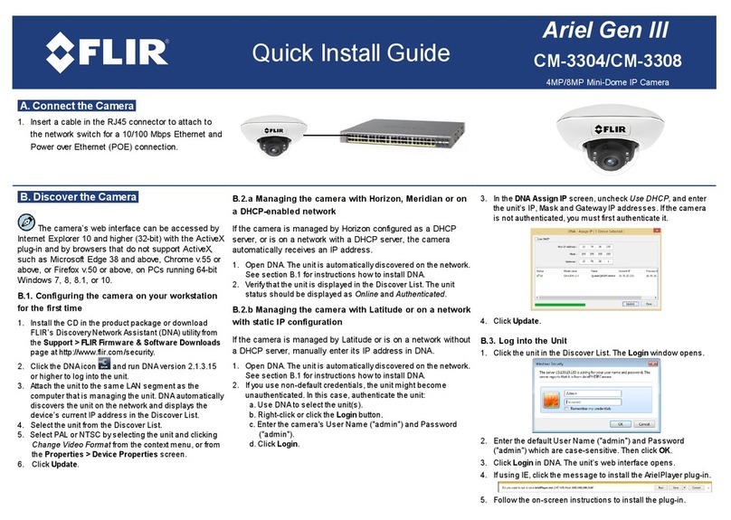
E. Configure RS485 and Inputs/Outputs
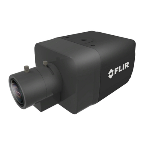
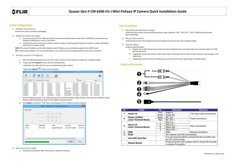
Connect the Camera Inputs and Outputs as required.
RJ45 port for Network and Power over Ethernet (PoE) connection
BNC connector for analog video outout.
Move toggle switch to left side to enable use of P-Iris lens.
Move toggle switch to middle to enable use of i-CS mount lens.
Move toggle switch to right side to enable use of DC-Iris lens. Also use this setting for Manual lenses.
Connector for attaching cable from lens.
microSD card drive supporting microSDXC card (up to 128GB). The card is not included.
Button to reboot the unit to full factory defaults. Network settings are not saved.
Male two-pin terminal block connector for attaching optional 12VDC or 24VAC power supply.
LED indicating Power On. The LED flashes green to indicate power on and network activity.
The link is not illuminated if there is no network activity.
Spring input terminals on terminal block for Positive (+) and Negative (-) wires from device attached via RS-485 serial
connection.
Spring input terminals on terminal block for COM, Ground, Alarm In, and Alarm Out wires.
Spring input terminals on terminal block for two Ground, Alarm In, and Alarm Out wires.
Press the button to activate Auto Back Focus. This button activates the One-Push AF feature on the System >Lens Control
screen.
F: Attach and Adjust the Lens
1. Remove the plastic insert covering the threaded camera lens
mount.
Do not touch the sensor or allow dust to accumulate in the lens
mount.
2. If you are using a C-mount lens, screw a 5mm adapter ring into
the C-Mount to convert it to a CS-Mount.
3. Align the lens threads into the lens mount and screw in the lens.
4. If you are using a manual lens, set the desired focus and zoom.
5. Depending on the lens in use, set the toggle switches (E.3,4,5
above) appropriately.
6. On automated lenses, connect the lens cable, and set the initial
adjustments maunallyand then use the web page or press the
ABF button to complete the setup.
G. Attach to VMS
Once you have completed installation and found the current IP address with DNA, use your VMS Discovery/Attach procedures to attach the camera to your VMS.
FLIR Systems, Inc.
Tel: +1-800-254-0632
6769 Hollister Ave.
product.enterprise.support@flir.com
Goleta, CA 93117
www.flir.com/security
