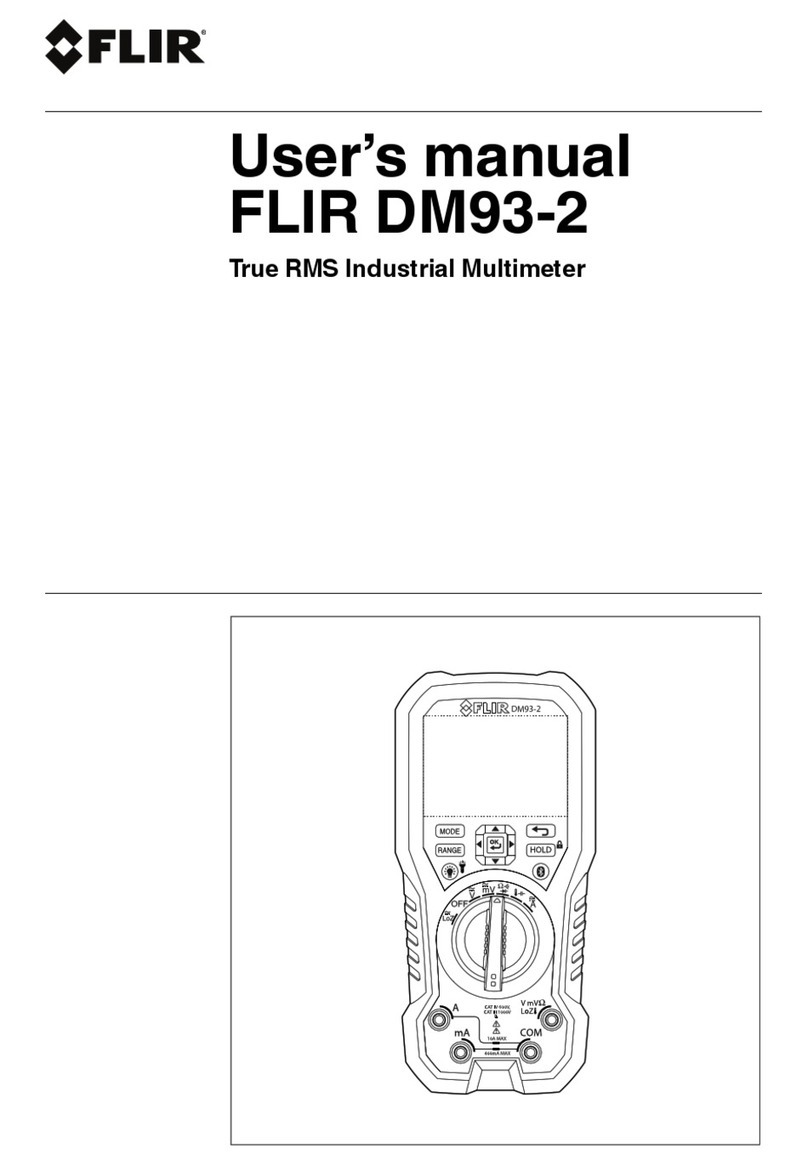
FLIR DM93-2 User manual
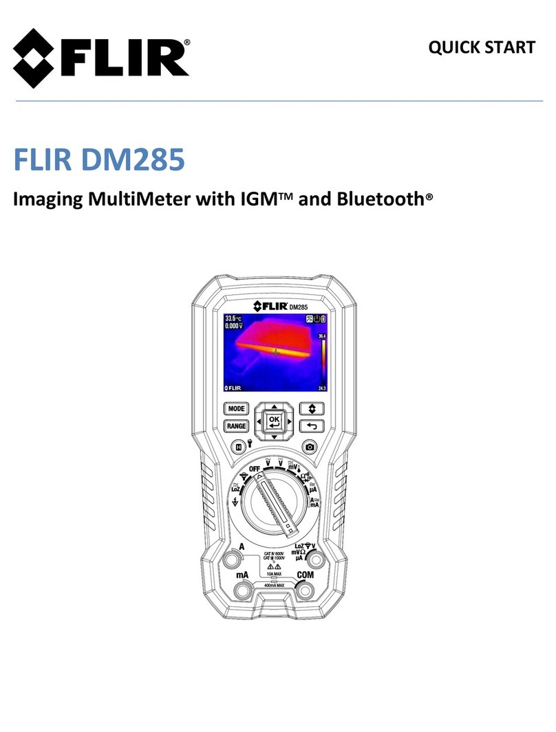
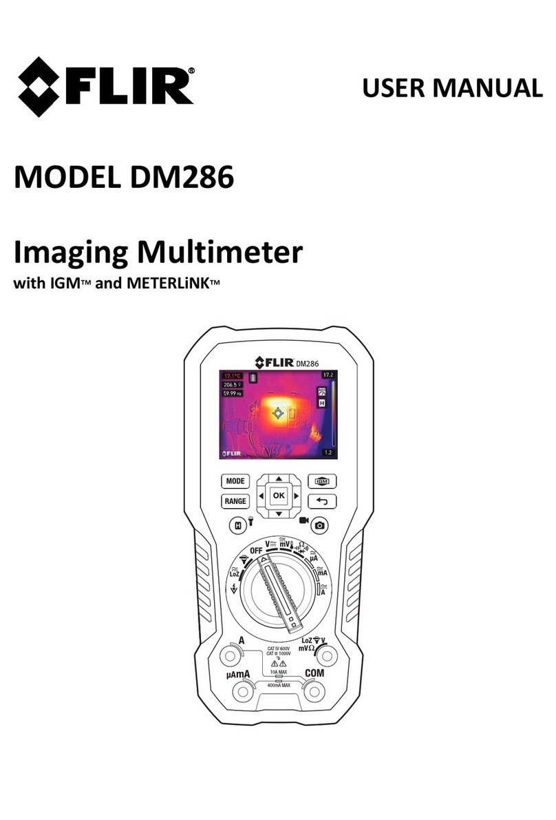
Other FLIR Multimeter manuals

FLIR
FLIR DM93 User manual

FLIR
FLIR MR160 User manual
FLIR
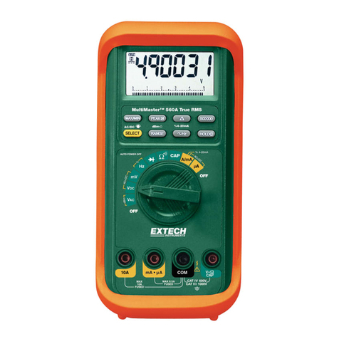
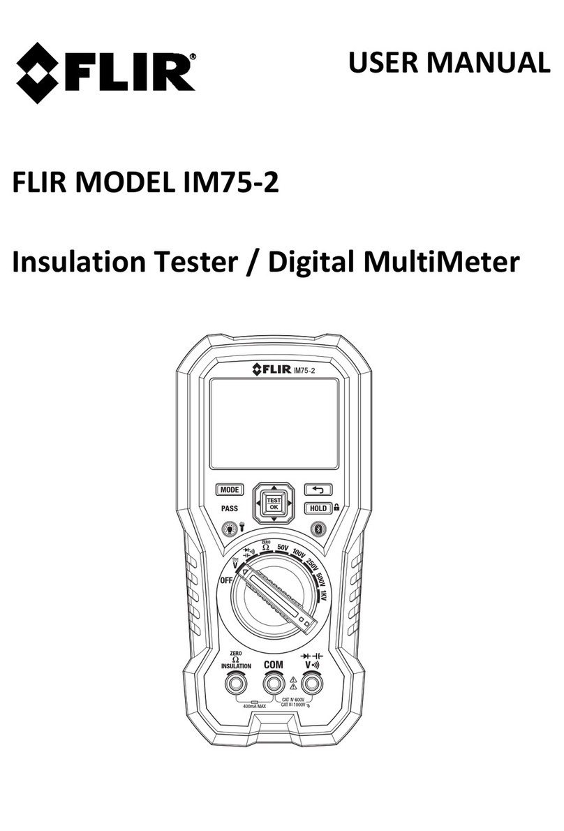
FLIR Extech Instruments MultiMaster MM560A User manual
FLIR
FLIR IM75-2 User manual

FLIR
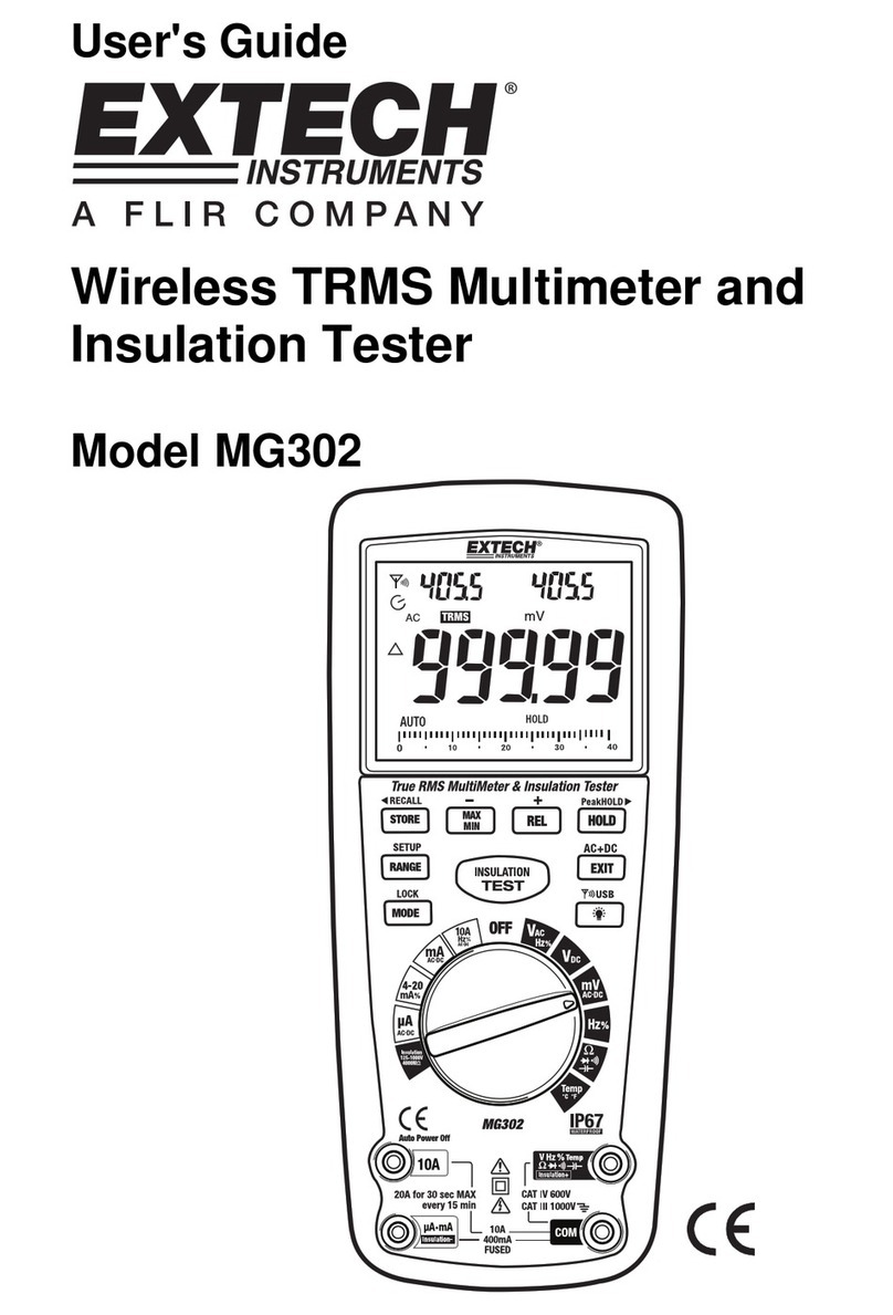
FLIR Extech EX510 User manual
FLIR
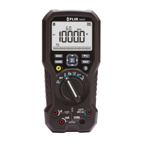
FLIR Extech Instruments MG302 User manual
FLIR
FLIR DM93 User manual

FLIR
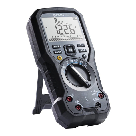
FLIR IM75-2 User manual
FLIR
FLIR DM92 User manual
FLIR
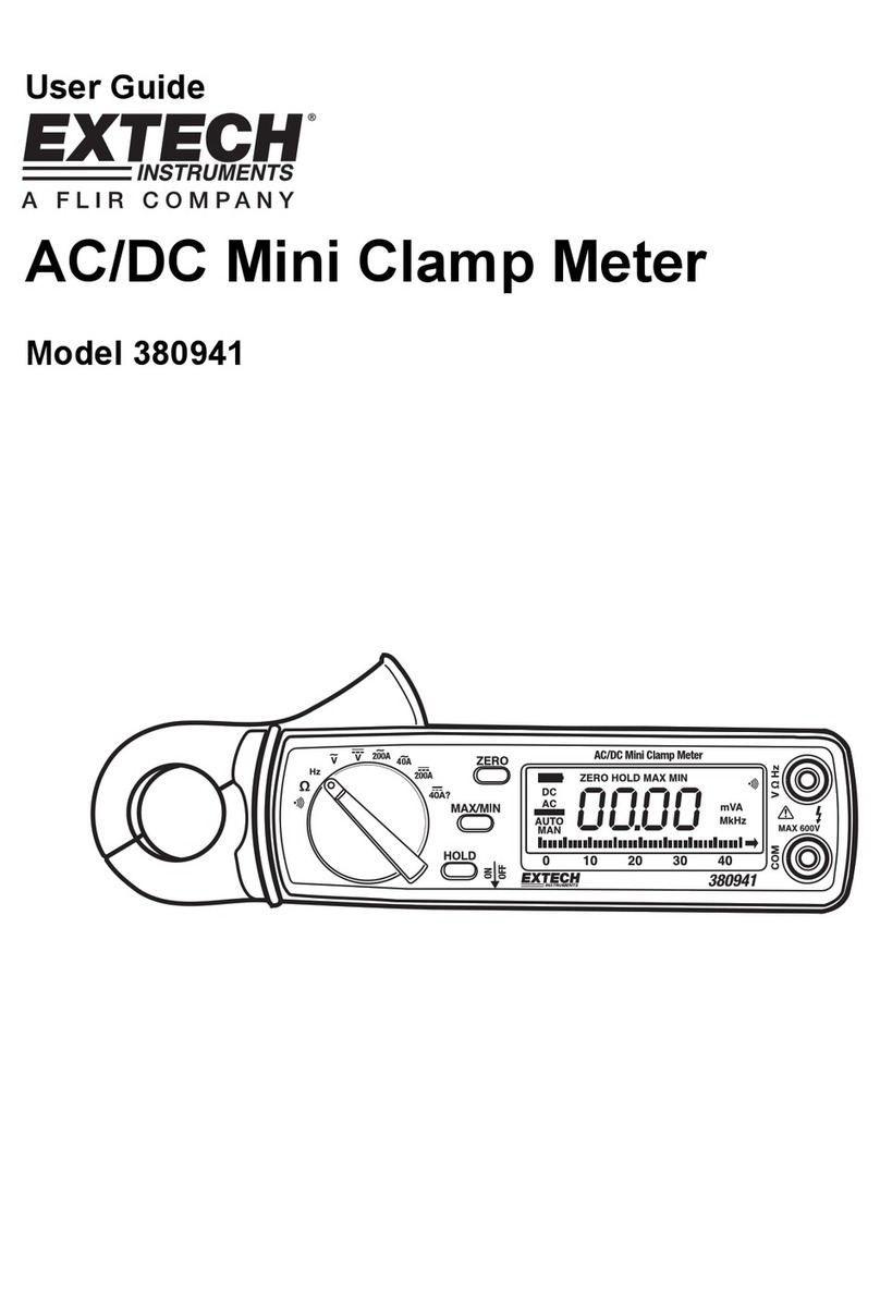
FLIR Extech Instruments 380941 User manual
FLIR
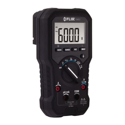
FLIR DM6 Series User manual
FLIR
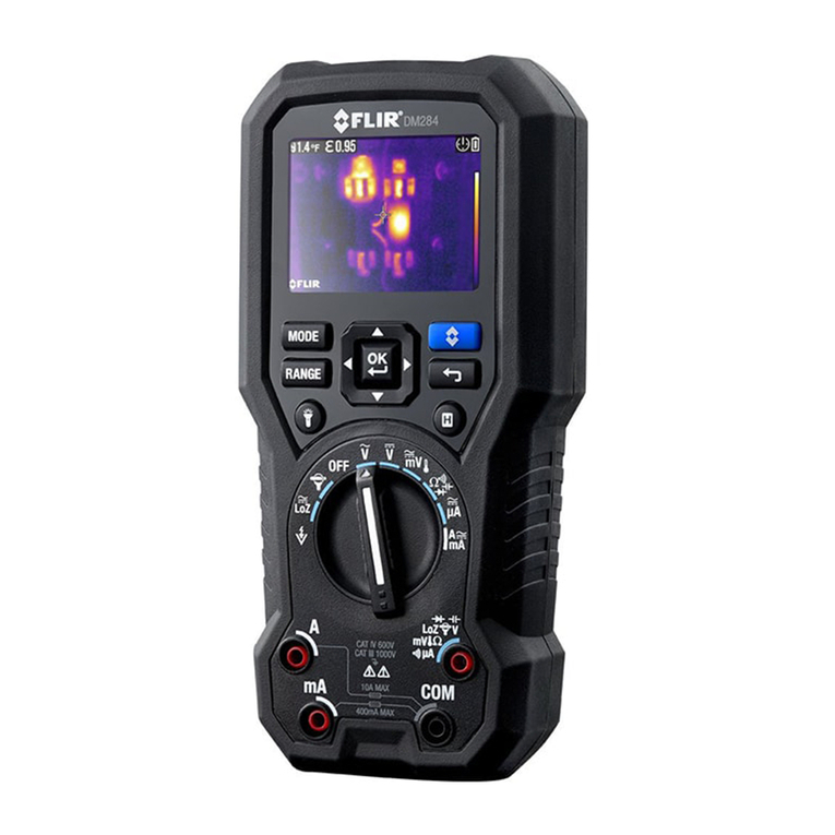
FLIR DM284 User manual
FLIR
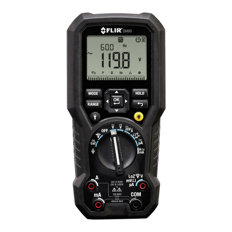
FLIR DM90 User manual

FLIR
FLIR DM90 User manual
FLIR
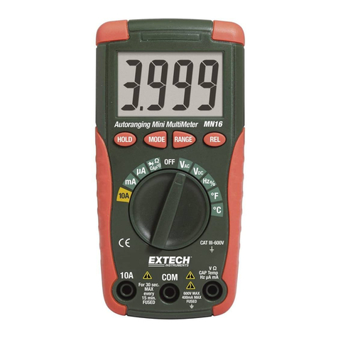
FLIR Extech Instruments MN16 User manual
FLIR
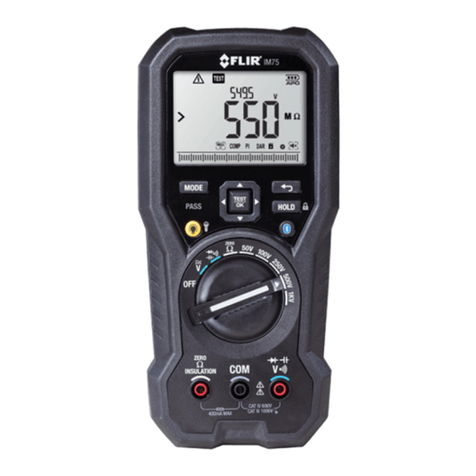
FLIR IM75 User manual
FLIR
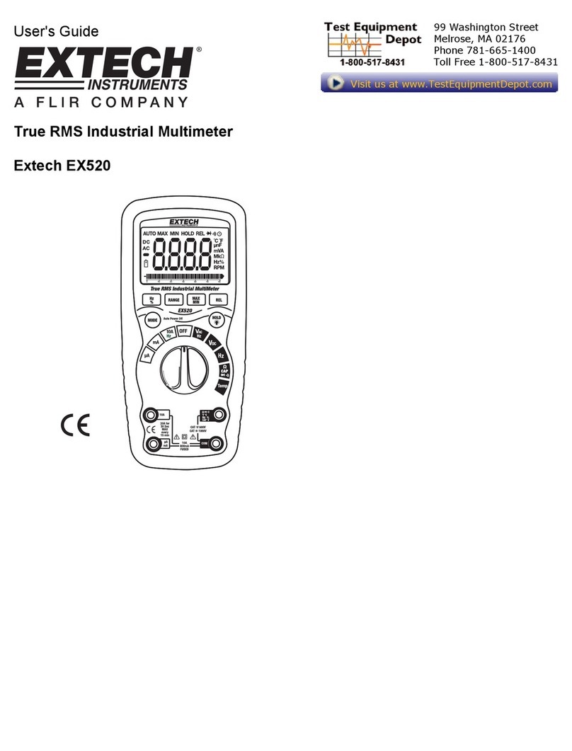
FLIR EXTECH INSTRUMENTS EX520 User manual

FLIR
FLIR EXTECH INSTRUMENTS MA120 User manual
FLIR
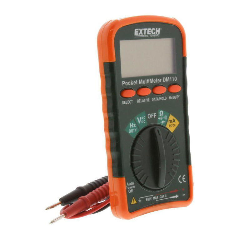
FLIR EXTECH INSTRUMENTS DM110 User manual

FLIR
FLIR DM90 User manual
Popular Multimeter manuals by other brands

Gossen MetraWatt
Gossen MetraWatt METRAmax 6 operating instructions

PeakTech
PeakTech 4000 Procedure of calibration

YOKOGAWA
YOKOGAWA 90050B user manual

Gossen MetraWatt
Gossen MetraWatt METRALINE DMM16 operating instructions

Fluke
Fluke 8846A Programmer's manual

Tempo Communications
Tempo Communications MM200 instruction manual
