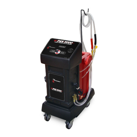
FLO-DYNAMICS C-VAC3 Installation and user guide

SectionOverview
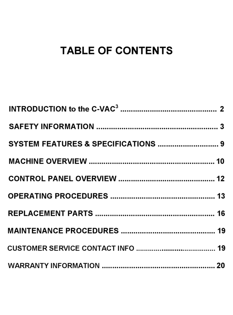
SECTION 1 - Table of Contents Pg.2
Section Overview Pg.3
Contact Information Pg.3
~ Getting Started Pg.4
Basic Tools Pg.5
Filter Screen Pg.6
Machine Cleanout Procedure Pg.7-9
Service Panel R & R Pg.10
Control Panel R & R Pg.11
Control Panel Exploded View Pg.12
SECTION 2 - Troubleshooting Pg.13
Common Problems & Solutions Pg.14
CVAC Wiring Diagram Simplified Pg.15
CVAC Hydraulic Diagram Simplified Pg.16
SECTION 3 - Service Procedures Pg.17
Service Hose R&R Pg.18
Battery Cable R&R Pg.19
Pump R&R Pg.20
Vacuum Generator R&R Pg.21
Vacuum Generator Exploded View Pg.22
Air Solenoid Valve R&R Pg.23
Pressure Gauge R&R Pg.24
Control Board R&R Pg.25
SECTION 4 - Tank Service Procedures Pg.26
Top Sink R&R Pg.27
~ Level Switch R&R Pg.28-30
Pg.28-29
Pg.30
Parts List Pg.31
Waste Tank Sensor R&R
New Tank Sensor R&R
Contact Information: If you are experiencing problems while servicing this machine please call us at 1-800-303-5874 ext.
2613 or email us at flotech@norcoind.com
9/24/2018CVAC3
3

FilterScreen
CVAC3 9/24/2018
1. Locate the external filter at the end of the black
service hose where it attaches to the machine.
Figure 1-1
2. Unscrew the cup portion from the filter housing.
Figure 1-2
3. This filter screen can be cleaned with tap water
and then blown out with compressed air. The screen
is permanently glued to the cup section of the filter
housing; do not attempt to remove it.
4. Replace the cup taking care not to pinch the
gasket.
6
FIGURE 1-1
FIGURE 1-2

MachineCleanout(1)
CVAC3 9/24/2018
If the machine is slow or stops flushing, but the motor
and air still operate, please follow these procedures.
Clean the filter(s): Cleaning the filters should be
done as a normal part of machine maintenance to
prevent problems from occurring.
1. Locate the external filter at the end of the black
service hose where it attaches to the machine.
Figure 1-3
2. Unscrew the cup portion from the filter housing.
3. This filter screen can be cleaned with tap water
and then blown out with compressed air. The screen
is permanently glued to the cup section of the filter
housing; do not attempt to remove it.
4. Replace the cup taking care not to pinch the
gasket.
Some of the older machines may also have an internal
filter (Figure 1-4) that can be cleaned or removed
(current production machines do not use an internal
filter).
To access and clean the internal filter:
1. Remove the rear bottom service panel behind the
machine and see if there is a filter attached to the
pump. It may be either a silver Y shaped filter, or a
black canister type. The silver version can be
opened and the screen cleaned; the black one may
be back flushed in the direction opposite the flow
arrow.
2. Clean either type with water or cleaner solvent
and blow out with compressed air.
7
FIGURE 1-3
FIGURE 1-4 Internal Filter
External Filter
Cup & Screen
Housing
MachineCleanout(2)
CVAC3 9/24/2018
Check for possible restrictions in the quick
disconnects at the ends of the hoses:
1. Unscrew the quick disconnect from the shut off
valve at the end of the hose. Figure 1-5
2. Inspect and clean valve and fitting if necessary.
Drain valve on the bottom of the used tank:
On newer machines (serial number 11921 and on),
there is a drain valve at the bottom of the machine
Figure 1-6. Carefully tilt the machine back, and have
another person open this valve over an area where
the coolant can be safely drained. Opening this
valve will drain fluid from the waste tank and should
clear the “T” fitting at the bottom of the tank of
accumulated debris. Older machines without the
drain valve can be cleared by removing the lines
from the “T” Fitting.
8
FIGURE 1-5
FIGURE 1-6
Remove on
Older Machines
New Machine
Drain Valve
Quick-Disconnect
Fitting
Shut-off Valve

MachineCleanout(3)
CVAC3 9/24/2018
To power flush the machine:
1. Confirm there is new fluid in both the red & green
tanks so the machine will operate.
2. Connect the red & black service hoses together
using the step adapters and the short section of
radiator hose provided with the machine. Figure 1-7
3. Connect shop air and a battery to the battery
cables.
4. Turn the top knob on the control panel so it is
pointing up to the “REMOVE FLUID” setting. Figure
1-8
5. Turn the bottom knob to either the “FLUSH RED”
or “FLUSH GREEN” position. Be sure there are at
least 4 qts of fluid in the chosen new fluid tank.
6. Turn on the “PUMP ON” and “VACUUM ON”
switches and watch for fluid flow in the hoses.
Figure 1-8
7. New fluid will be pumped through the machine,
while the vacuum will pull new fluid through the
system into the used tank. If there is any foreign
material in the lines, this should force it out after a
minute or so.
Occasionally it is helpful to rotate each one of the
knobs around a few times while the flush is
running if no flow is seen, then return them to their
previous position. 9
FIGURE 1-7
FIGURE 1-8
(2) Step
Adapters
Radiator Hose
Adaptor
Both
Switches On

ControlPanel
CVAC3 9/24/2018
1. Turn both knobs to the upward position, &
remove using a Philips-head screwdriver. Figure 1-
11
2. Remove 4 way ball-valve mounting nuts with 3/4"
open-end wrench. Figure 1-11
3. Using 1/8” hex head wrench, remove the [5]
screws securing the service panel. Figure 1-12
4. With 7/8” open-end wrench, disconnect the [2]
hoses from the pressure gauge. Figure 1-12
5. Disconnect wire terminals & harness. Figure 1-13
6. Remove control panel from the machine.
7. To install reverse steps. (Parts Breakdown on
Pg.12)
11
FIGURE 1-11
FIGURE 1-12 FIGURE 1-13
(5)1/8” Hex
Remove
Remove

CVAC3 9/24/2018
12
CVACControlPanelExplodedView Item Part # Description Qty
1 P941315 Control Panel –Black 1
2 941227 4-Way Valve 2
3 940124 Male Connector 3/8 –1/2 2
4 940114 90 Deg Elbow 6
5 941278 2.5 Panel Gauge & U-Clamp 1
6 941409 Control Box –CVAC3 1
7 941341 2-Way Pump Switch 1
8 941342 3-Way Vacuum Switch 1
9 941324 Tee Fitting (Gauge) 1
10 941329 Elbow Fitting (Gauge) 1
11 941327 Male Connector Gauge 1

CommonProblems&Solutions
1) Machine will not power up.
a. Verify the Power Source produces 12.6v or higher.
b. Verify the Battery Cables are tight, clean and are not
damaged in any way.
c. Check the Fuse (Behind the Lower Rear Service
Panel)
d. Verify ALL Wiring Harness Pin connections are tight,
no loose or damaged wires.
2) Machine will not Add Fluid.
a. Verify BOTH New Fluid Tanks have adequate fluid.
Red LED light will be on if Fluid is Too Low.
b. Verify Red Service Hose ball valve is in the Open
position. Verify that the Quick disconnect fitting is
completely connected to the adapter.
c. Verify New Fluid Tanks don’t have debris buildup in
the bottom of the tank, debris can affect proper Float
Switch movement.
d. Machine may have an internal clog, Power-flush the
machine to push & pull the clog out of the internal
lines. Refer to Machine Cleanout 3 Pg.9
e. Verify the Pump is working, verify the Pump Switch is
operable also.
f. New Tank Float Switch may be bad.
g. Pump may be bad.
3) Machine will not Remove Fluid.
a. Verify Machine is connected to shop air and it
produces at least 115psi.
b. VerifyAir is heard when turning on the Vacuum
Switch.
c. Verify the Black Service Hose ball valve is in the
Open position. Verify that the Quick disconnect fitting
is completely connected to the adapter.
d. Verify the Black Hose external filter isn’t
clogged.
e. Machine may have an internal clog, Power-
Flush the machine to push & pull the clog out of
the internal lines.
f. Verify the Vacuum Generator is not clogged
with debris or damaged, the muffler is not
damaged/missing. Verify the air lines are fully
connected and not clogged, leaking or
damaged.
4) Machine will not Drain Waste Tank.
a) Verify no clogs are in the internal lines, power
flush the machine to push & pull the clog out of
the lines. Then try to drain waste tank.
b) Machine may have debris built up on the
bottom of the waste tank, machines waste tank
will need to be cleaned out. Check if the
manual waste tank drain will allow fluid to drain.
If not machine will need a waste tank cleanout.
5) Machine will not perform the service indicated
on the Dials or Switches.
a) Knobs are in the wrong position, Remove dial
and reverse the direction of the arrow on the
knob.
b) Verify both Switches are wired correctly. See
Wiring Diagram Pg.15
c) 4-way valve may be worn, replace the 4-way
valve.
9/24/2018CVAC3
14

ServiceHoses
CVAC3 9/24/2018
1. Use 1” open-end wrench to hold top nut in place,
while loosening bottom nut with 7/8” open-end
wrench. Reverse procedure to install.
Service Hose Parts Numbers:
941467 –Black Service Hose (New Style)
Figure 3-1
R941345 –Black Service Hose
941346 –Red Service Hose Figure 3-1
18
FIGURE 3-1
941346
941467

BatteryCables
CVAC3 9/24/2018
1. Remove bottom service panel using 1/8” hex-
head wrench.
2. Unplug the two wires shown, and untie knot in
cord. Figure 3-2, 4
3. Cut terminals off with wire cutters, and pull the
old cables out from bottom. Figure 3-3
4. Slide the replacement cables up through rubber
grommet, and crimp new terminals to the wire ends
with a crimping tool. Figure 3-4
5. Tie a knot in the cord to prevent it from being
pulled out of the machine, and re-connect both
terminals as shown. Figure 3-4, 2
NOTE: The printed wire is positive, and connects
to the red wire inside the machine.
19
FIGURE 3-2
FIGURE 3-3
FIGURE 3-4
Battery
Cable Wires
Rubber
Grommet
Printed Line
is Positive +

Pump
CVAC3 9/24/2018
1. Remove bottom service panel using 1/8” hex-
head wrench.
2. Disconnect all hoses & wires from pump. Newer
model pumps will have tabs to release the hose
barbs from the pump. Push tabs towards the front of
the machine then pull the barb & attached hose out
of the pump. Figure 3-5
3. Using a 1/8” hex-head wrench, remove the [4]
mounting screws, while holding the bottom nuts with
a 3/8” open-end wrench. Be careful not to drop
them into the machine. Figure 3-7
4. Remove old pump & replace with new pump.
NOTE: Be sure to apply thread-sealer before re-
connecting any hose fittings.
20
FIGURE 3-5
FIGURE 3-6 FIGURE 3-7
Remove
Tab Forward
Pump Wire
Green (Power)
Pump Wire
Black (Ground)
(4) 1/8” Hex
Other manuals for C-VAC3
1
Table of contents
Other FLO-DYNAMICS Service Equipment manuals

FLO-DYNAMICS
FLO-DYNAMICS BrakeMate Jr Programming manual

FLO-DYNAMICS
FLO-DYNAMICS TS650M User manual

FLO-DYNAMICS
FLO-DYNAMICS RADCVAC3 User manual

FLO-DYNAMICS
FLO-DYNAMICS TTCF-8 Manual

FLO-DYNAMICS
FLO-DYNAMICS HEAVY DUTY DCF-35 User manual

FLO-DYNAMICS
FLO-DYNAMICS BrakeMate User manual

FLO-DYNAMICS
FLO-DYNAMICS VacFill3+ Installation guide

FLO-DYNAMICS
FLO-DYNAMICS TSD450 Programming manual

FLO-DYNAMICS
FLO-DYNAMICS TSD450 User manual

FLO-DYNAMICS
FLO-DYNAMICS TS410 Programming manual