Floe VSD 3800 User manual

1
OWNER’S MANUAL
VSD-3800, VSD-5000
& VSD-5000 for pontoons
24 volt DC / 120 volt AC
Boat Lift Systems
(patented Easy-Level Leg System)
Read and follow all safety rules and operating instructions
carefully before attempting to install or operate lift system.
ATTENTION ATTENTION ATTENTION
Visit our website at www.floeintl.com
Retain this manual for future reference
Watch our customized boat lift setup and installation video:
www.floeintl.com/manuals-information

2
Congratulations on the purchase of your new FLOE Boat Lift!
Like you, I enjoy many kinds of waterfront activities, and I know that to have fun I
need to keep my boat secure, protected, and accessible. Through my years of experi-
ence, I’ve learned how boat lifts should not only protect your watercraft investment,
but also be convenient and easy to use - and I have developed them accordingly.
The fact that you purchased a FLOE boat lift tells me that you research a product
thoroughly. You will nd a FLOE boat lift has many innovative features that will ensure
years of dependable service, satisfaction, and enjoyment.
Because your FLOE boat lift is engineered to lift and support a tremendous amount of weight, it is critical that you operate
it safely. Anyone who operates this lift must read the entire owner’s manual before operating the lift to make sure they are
able to operate it properly and enjoy all of its features to the fullest. See you on the water!
Wayne Floe , CEO - FLOE International
Important Safety Information .................2-4
Letter from Wayne Floe .........................2
Certicate of Boat Lift Pre-delivery........5
Boat Lift Capacities................................6-7
Boat Lift Dimensional Specications .....8
Drive Train & Ball Screw........................9
Power System .......................................10-11
Limit Switch ...........................................12
How to Raise & Lower Lift .....................12
Wired Remote........................................13
Wireless Remote .................................. 14
Leveling Boat Lift...................................14-15
Boat Lift Installation & Removal Options ..16
Boat Lift Wheel Kits ...............................16
Float & Roll............................................17
Insta-Float..............................................17
Full Length Bunk Set Up........................17-18
Cradle Pad System................................18
Pontoon Guide-In/Bunk System ............19-20
Carpeted Guide-In System........................ 20
Vertical Guide-In Selection & Adjustment ..21
Adjusting Guides ....................................... 21
Boat Placement/Motor Stop....................... 22
Proper Canopy Frame Positioning ............ 22-23
Telescopic Canopy End Frame Adjustment 23
Canopy Fabric Installation......................... 23-24
Canopy Wind Precaution........................... 24
Canopy Fabric Removal............................ 25
Canopy Fabric Folding Instructions...........
25
Canopy Fabric Care & Cleaning................
25
Optional Canopy Lighting Package ...........
26
Inspections & Maintenance .......................
26-29
VSD Kit Troubleshooting ...........................
29-30
VSD-3800 Parts List.................................. 31
VSD-3800 Exploded View .........................
32-33
VSD-5000 Parts List..................................
34
VSD-5000 Exploded View .........................
35-36
Warranty and Registration.........................
37-38
CONTENTS
It may also be benecial to view the lift portion of
FLOE’s marine video, “A Look Into FLOE Dock & Lift
Systems.” See it on our website in streaming video.
Please retain this manual for future reference

3
This manual includes the latest information at the
time it was printed. We reserve the right to make
changes in the product after that time without
notice. Keep this manual so it will be available
to who ever is using this product.
3
While operating the lift, keep all body parts, long
hair, loose clothing and jewelry away from all
moving parts, including (but not limited to) the
drive-train mechanism, cables, pulleys and lift
platform.
Be sure the lift cradle is completely lowered
before any adjustments or repairs are made to
the winch.
Always keep all people clear of the boat lift support
structure and lifting cradle. Never swim or play near a
boat lift, even if it is not being operated.
Make sure the boat lift is completely clear of
people or other obstructions prior to operating.
Do not operate a boat lift with people inside the
boat.
Never operate a boat lift with protective cover
removed from drive train system.
Never allow anyone on or under this lift system,
especially while it is being operated, or it is sup-
porting the weight of a watercraft.
Stay clear of boat lift when someone is entering
or exiting the lift with a boat. Never try to assist
the boat’s direction while it is in motion (either
from inside or outside the boat).
Never work on or make adjustments to boat,
boat lift or boat lift accessories while the lift is
supporting the weight of the boat.
IMPORTANT SAFEGUARDS
Read and follow all safety rules and operating instructions carefully
before attempting to install and operate lift system
DANGER CAUTION
WARNING
You will be killed or seriously injured if
you don’t follow instructions.
You can be killed or seriously injured if
you don’t follow instructions.
Failure to take appropriate action
could result in mechanical failure,
product damage and/or
cause serious injury or potential death.
Your safety and the safety of others is very important. We have
provided many important safety messages in this manual and on
your lift system. Always read and obey all safety messages.
If you do not understand any of these instructions,
please ask your dealer or call FLOE Customer Service at
218-426-3563 or toll free 800-336-6337.
This is the safety alert symbol. This symbol alerts you to
hazards that can cause serious injury or potential death to
you and others, plus damage to the lift system. All safety
messages will be preceded by the safety alert symbol and
the word “DANGER”, “CAUTION” or “WARNING.”
IMPORTANT SAFETY INFORMATION
All safety messages will identify the hazard and tell you how to reduce the chance of injury.
DANGER
CAUTION
WARNING

4
If this unit is equipped with a canopy, severe wind
damage may occur if the lift is not securely held
down to the lake bottom by screw anchors or by
some other means.
FLOE lift systems have not been tested in brack-
ish or salt water conditions. Lift failures due to
installations in brackish or salt water locations will
not be covered by FLOE’s warranty. FLOE will
not be responsible for incidental or consequential
damages resulting from these installations.
Never install the lift system in a body of water
whereas either the rising water or wave action
will not always flow under the main lift beam. For
example, do not install lift in bodies of water with
significant water fluctuation or large water bodies
that have excessive wave action.
4
Lift must be assembled and installed properly or
mechanical failure and possible injury may occur.
Never overload a boat lift. See capacities/specifi-
cations for important information regarding the
boat’s actual weight and boat lift capacity limita-
tions.
Never operate a boat lift that is not level. Under
normal conditions a boat lift operates under
extreme force. When the lift is not level, these
forces are greatly multiplied and bodily injury or
damage to the lift can result.
Perform all inspections and maintenance on a
regular basis. Replace any worn parts immedi-
ately to avoid potential lift failure. Ensure all pul-
leys are operating properly and that all cables
and their attach points are secure and free of
excessive wear and fraying. See Inspections &
Maintenance section for all important details.
Bodily injury or damage to lift system may result
if installation or removal of this lift is attempted
without first reading and understanding the instal-
lation and removal section of this manual.
WARNING
This manual is intended to serve as an owner’s use and maintenance guide for a lift that has been
properly assembled by a qualified, trained professional. Detailed assembly instructions
are packaged with the lift systems.
If the boat lift system is not assembled, installed, or operated properly, mechanical failure,
as well as serious injury or death, could result. See to it that all users understand
that this lift system is a piece of heavy equipment that requires the use of good
judgement and the knowledge of its dangers and limitations.

5
Certicate of
Boat Lift Pre-Delivery
All dealers should have reviewed the checklist below with retail customers upon
purchase of a boat lift. If they did not cover this, retail customers must review
thoroughly and understand the statements below.
Date of Purchase ______/______/______ Boat Lift Model ______________________________________
Customer Delivery: Each item must be initialed by the selling dealer upon sale.
______ I understand that the boat lift must be properly assembled and must be tested prior to use with a boat.
______ I understand that a serious injury or death could occur if a boat lift is overloaded, not correctly assembled,
installed, maintained or not used properly.
______ I was given an owner’s manual and I promise to read and understand it before using the boat lift.
______ I understand that it is my responsibility to get clarication on anything in the owner’s manual that I don’t fullly
understand before using the lift system.
______ I understand that I must educate all persons who will be around or using my boat lift as to how to do so safely.
______ I understand that people must stay clear of the boat lift when it is supporting the weight of the boat. No one
should ever swim under it, be on it, in the boat, or in any position that could cause harm to them if the lift
were to suddenly drop.
______ I understand safe operation of the lift requires people to stay clear of moving parts and pinch points.
______ I understand that a boat lift should never be overloaded under any circumstance. A boats published dry
weight is usually substantially lower than its actual loaded weight. Your boat should be weighed with fuel,
water, batteries and contents in order to know its actual weight.
______ I understand the total capacity of the boat lift is equal to the combination load limit of the two main end lift
beams. For instance, a lift with a 5,000 pound capacity has a load limit of 2,500 per lift end beam.
______ I understand that a 5,000 pound total boat weight could easily over-load one of the main lift beams on a
5,000 pound capacity lift. For instance, if the boat was positioned so that one main lift beam supported 3,000
pounds and the other only supported 2,000 pounds, the lift would be over-loaded. For this reason, FLOE
recommends that your total loaded boat weight doesn’t exceed 85% of the lifts rated capacity and that you
locate and place the boat’s center of gravity (balance point) in the center of the two lift beams.
______ I understand that the boat lift needs to be installed level and must be kept level while it is in use. A lift that
isn’t level will have a reduced lifting capacity of 5% per 1” of being out of level.
______ I understand that I need to pull the drain plug on my boat if it is subject to water accumulation as this could
easily overload the boat lift.
______ I understand that I should never lift my boat if it has been swamped or has any signicant additional water
weight in it that will overload the boat lift’s capacity.
______ I understand that if my lift is equipped with a canopy it must be properly secured or it could blow over and
cause damage not covered under warranty.
______ I understand that I must discontinue using the lift immediately and contact my FLOE dealer if any unusual
sounds or functionality are present.
______ I understand I must follow all inspection and maintenance procedures as outlined in my owner’s manual.
Selling Dealership Name_________________________________________________________________________
Selling Dealership Signature_______________________________________________________________________
Print Name
Customer Signature_____________________________________________________________________________
Print Name

6
LIFT CAPACITIES
It’s recommended that the total loaded weight of
the water craft doesn’t exceed 75-85% of the to-
tal lift capacity. The total capacity of a lift is the
combined capacity of each of the boat lifts two
main lifting beams.
Never exceed the weight capacity of either main
lift beam. For instance a 5,000 lb capacity boat lift
is limited to 2,500 lbs for each main lift beam. It is
very easy for a 4,000 lb boat to exceed the capac-
ity of a 5,000 lb boat lift by not parking on the lift in
the correct position.
BEFORE PUTTING A BOAT ON THE
LIFT YOU NEED TO KNOW THREE
VERY IMPORTANT THINGS:
1. Determine the total loaded boat weight?
Weigh your boat loaded with fuel, water and ev-
erything in that you could ever have in it when it is
parked on the boat lift. Not all manufacturers pub-
lished boat weights are accurate because they
don’t account for motors, gear, fuel, water, etc.
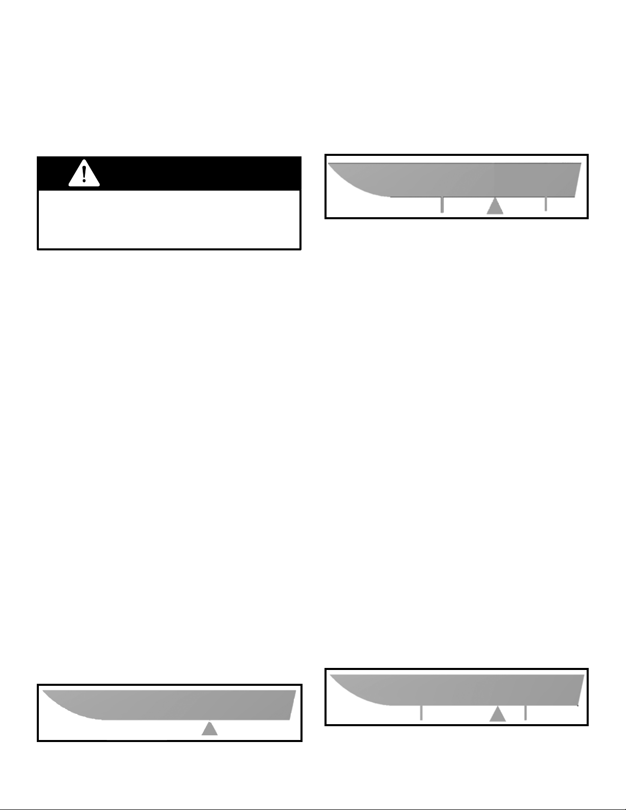
2. Determine the boats center of gravity or CG?
A boat’s CG is the location under the boat hull
which the boat will balance if sitting on a narrow
object ((Illustration A). Your dealer or the manu-
facturer of the boat should be able to help you
locate the boat’s CG. Be sure that the motor and
gear weight have been taken into consideration.
Never exceed the lift’s rated capacity. Doing
so could cause structural/mechanical failure
and serious injury or death.
WARNING
3. Determine that the boats center of gravity (CG)
is centered between the two main lift beams
The boat should be parked so that the boat’s CG
or balance point is centered between the two
main lift beams (Illustration B). Each of the lift
beams should be supporting the same amount of
weight.
Once you know that your boat is well within the
boat lifts rated capacity and the location of the
boat’s CG develop a positioning method that will
ensure that all users of the boat lift will park with
the Boat’s CG in the center of the lift. Here are a
couple of suggestions to do this consitently:
• Use a motor stop.
• Note the proper location of the boat on the lift
and use some sort of marking system or labels.
• If equipped with canopy, center the canopy
over the boat when the boat’s CG is in the
center of the lift, park with the boat centered
under the canopy.
• You can even hang an object such as a
tennis ball so it just touches the windshield
when the boat is properly positioned.
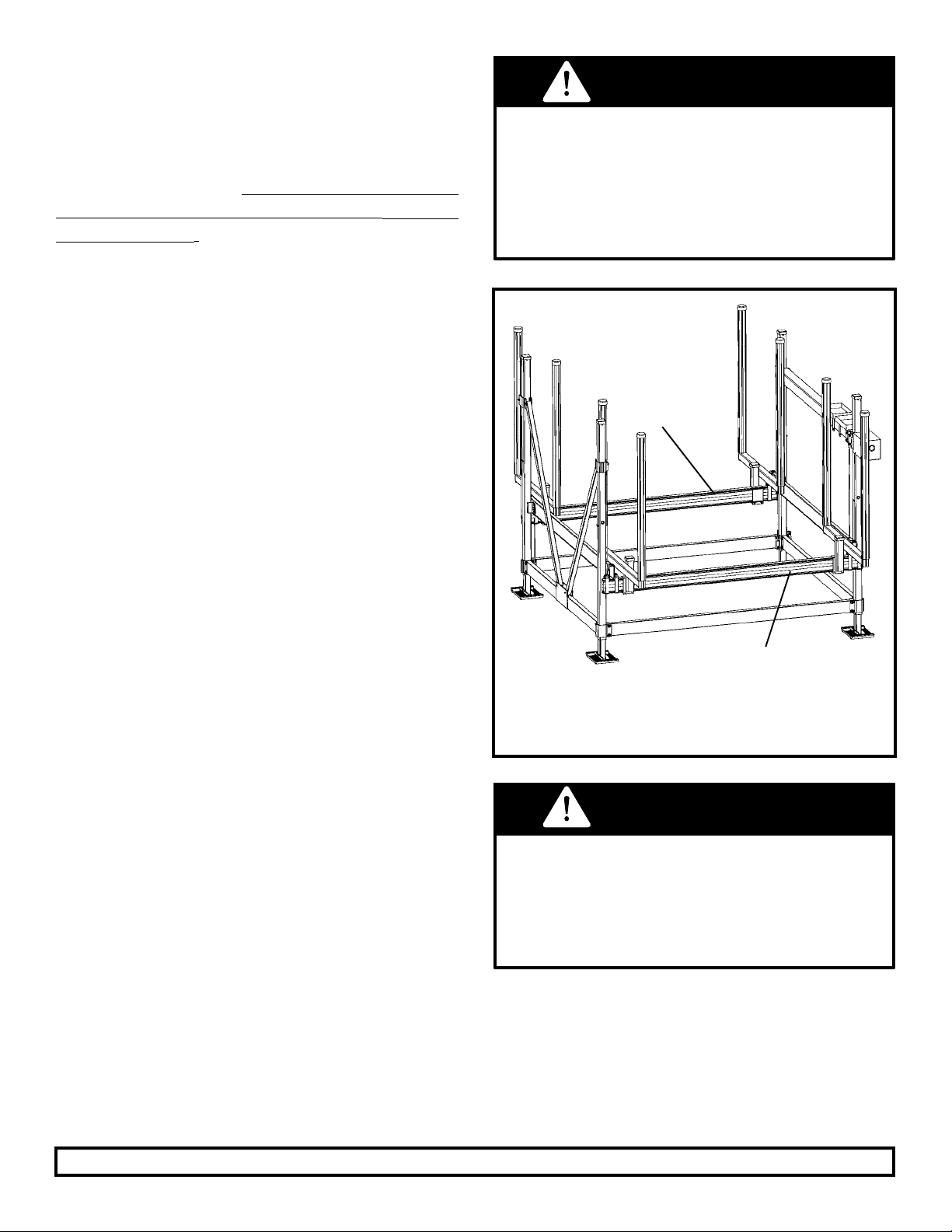
If your boat is not positioned properly, you can
extremely overload one of the main lifting beams
(See Illustration C, below).
Illustration A: above shows the boat’s balance
point of center of gravity (CG).
x
Illustration B: shows the boat’s center of gravity
(CG) centered between the two main lift beams
– each of the lift beams is supporting the same
amount of weight.
Illustration C: shows a boat’s center of gravity
(CG) improperly positioned so that it extremely
overloads one of the main lifting beams.

7
HOW TO DETERMINE IF YOUR LIFT’S
TOTAL CAPACITY IS ADEQUATE FOR
YOUR BOAT
One way to determine whether the lift’s capac-
ity is adequate is to log onto FLOE’s website,
www.oeintl.com, and click on the Boat Lift
Selector program. This program will calculate opti-
mal boat positioning and guide you to the best lift se-
lection for your boat. It even has a link that will help
you determine the weight of your craft. Your dealer
can also assist you in making the best choice.
The following simple exercise is a second, but
less accurate way, to manually determine the lift
capacity needed for your boat:
1. Obtain the boat’s actual total weight including
motor, fuel, water, equipment, accessories, etc.
2. Subtract the weight of the motor and fuel from
this number.
3. Take the boat’s weight, (the result of step 2), di-
vide it in half and add the weight of the motor and
fuel to that number. This number is the approximate
weight that the rear lift beam will need to support.
4. Take this number and multiply by two. This will
equal the approximate minimum rated lift capacity
needed for the boat.
For instance: If the boat is an I/O that has a total
loaded weight of 2900 lbs. and the fuel, motor and
lower unit weigh approx. 800 lbs. it would be calcu-
lated as follows:
• 2900 - 800 = a boat only weight of 2100 lbs.
• 2100 / 2 = 1050 lbs. This is the approximate
boat weight that will be supported by each lift
beam (not including motor and fuel).
• 1050 + 800 = 1850. This is the approximate
actual weight that the rear beam will need to
support.
• 1850 x 2 = 3700. This is the minimum overall
boat lift capacity needed.
This example does not include any additional hard-
ware or accessories that would affect the capacity
needed.
If watercraft is open to the accumulation
of rain water, be sure boat’s drain plug is
pulled. Additional water weight may cause
the maximum lift capacity to be exceeded,
resulting in potential lift damage or bodily injury.
This is a guideline only. It is the operator’s responsibility to ensure capacities are not exceeded.
You must weigh your boat fully loaded,
including fuel, gear, etc. to get its accurate
weight. It is common for published dry weights
to be considerably lower than actual loaded
weights. Lift and/or boat damage due to
overloading is not covered by your warranty.
WARNING
WARNING
VSD-5000
Each lift beam has a total capacity of 2500 lbs and is
rated to support one-half of the lift’s total capacity.
MAIN CRADLE
LIFT BEAM 1
MAIN CRADLE
LIFT BEAM 2
Fig. 1

8
* Deep water extensions available. ** Does not include the weight of the bunks, guides, or other accessories.
LIFT DIMENSIONAL SPECIFICATIONS Specications may change without notice.
MODEL/
CAPACITY
DRIVE TRAIN BUNKS BED
TRAVEL
INSIDE
WIDTH
OUTSIDE
WIDTH
FRAME
LENGTH
VSD-3800-lb.
& VSD-5000-lb
Screw-Drive Full Length Bunks
Cradle Pad Pivot Bunks
Pontoon Full Length Bunk
or Cradle Pad Systems
52” 116.5” 122.5” 109.5”
Max. Inside Width of Guide-ins
(Single Vertical or Horizontal With Vertical Bum-
pers) 102”
104.5”
Max. Inside Width of Double Vertical
Guide-in Style Only
Top of Main Cradle
Lift Beam lowers down
to 9.5” above the lake
bottom with legs fully
retracted.
122.5”
Outside
Frame Width
109.5”
Frame Length
(from one main
lift beam to the
other)
Outside edge of sandpad to
outside edge of sand pad 129”
0-30” Leveling Leg Travel
with Standard Legs
28.5-50.5”
Leveling Leg
Travel with
Extensions*
Bed
travel
for
VSD-
3800
& VSD-
5000
52”
MODEL/
CAPACITY
LEVELING
LEG TRAVEL
TRAVEL WITH
EXTENSIONS
CANOPY
OPTION GUIDE-IN
OPTIONS
MAX INSIDE
WIDTH WITH
GUIDE-INS WEIGHT**
VSD-3800-lb.
& VSD-5000-lb
0-30” 28.5” - 50.5” 22’, 24’, 26’,
28’, 30’
Horizontal with
Vertical Bumpers
Single Vertical
Double Vertical
102”
102”
104.5”
486 lbs.
536 lbs.

9
Limit Switch
Ball Nut
Galvanized
Steel
Lifting Cable
Rotating Screw
The drive train simply spins
the
screw so that the ball nut
travels
back and forth as it
pulls the lifting cable.
Fig. 3
DRIVE TRAIN & BALL SCREW
This boat lift is equipped with FLOE’s exclusive
Vertical Screw Drive (VSD) drive train technolo-
gy. The VSD system replaces the common winch
style drive-train common to most
boat lifts. It uses a DC or AC powered, high-torque
electric motor along with a ball-screw and ball-nut
mechanism. See Fig. 2.
When operated, the motor turns the ball-screw,
allowing the ball-nut to travel back and forth
along the screw. This raises and lowers the lift as
shown in Fig. 3.
Maintenance and trouble-shooting tips for the
exclusive drive-train system are addressed later
in this manual.
This efcient drive train has enabled FLOE to
design a lift for mid-sized boats that is easily
powered by a 24-Volt battery system or a 120-
Volt AC power system, and to develop a line of
optional accessories to keep the batteries charged
effortlessly.
To prepare your VSD lift for operation, you should
rst understand the basics for setting up the
electrical features of the lift, and especially the
importance of the limit switch safety feature.
Fig. 2
Drive Train
Power Unit
& Ball Screw
ADVANCED SWITCH CONTROL (ASC)
The electrical connection panel (Fig. 4) is located
on a separate box. It is designed to allow for easy
hook up of standard and optional components as
well as the resetting of tripped circuits.
• The black wire is for the limit switch.
• The blue wire is for the wired remote/key switch.
• The yellow wire is for the wireless receiver.
The resetable circuit breakers are designed to
trip if there is a short in the wires. The DC version
has one reset for the radio remote receiver and
the optional ood lights.
The AC version has two
resets, one for the radio
remote receiver and op-
tional ood lights and the
other reset is for the drive
motor. If one trips you can
reset it by pressing in the
reset button (Fig.5). If it
contiously trips refer to
the trouble shooting sec-
tion of this book.
Black Wire
Limit Switch
Yellow Wire
Wireless
Receiver
Blue Wire
Wired Remote
Fig 5
Reset
Advanced Switch Control (ASC) 24 volt DC
powered unit (above).

10
CHECK THE FOLLOWING TO ENSURE
PROPER OPERATION OF THE
ELECTRIC MOTOR DRIVE
Electrical System:
1. Power wires to the batteries & motor are prop-
erly connected, corrosion free & tight.
2. Batteries are fully charged. When tested a 12
volt battery will have between 12.7 and 13.8 volts.
3. Limit Switch is connected to 13-in. plug.
4. Wired Remote/Key Switch is connected to
10” plug.
5. Wireless Receiver (optional) is connected to
7” plug.
Important:
• Test the upper & lower limit switches before ini-
tial use and seasonally to ensure the drive motor
shuts off automatically before coming to a hard
stop. Test by approaching the upper & lower cra-
dle positions cautiously with quick on/off triggers
of the remote.
• If any portion of the electrical system is sub-
merged, please refer to the owner’s manual for
corrective action.
Cable Note:
• Ensure that cradle travels freely to the bottom
of the lift and keeps tension on lifting cable at all
times.
120 VOLT AC WARNING
For the AC power
connection please
contact a licensed
electrical contrac-
tor to ensure a
safe connection.
You must have
120v/20amp ser-
vice to the con-
nection on VSD
drive train.
Keep the cables from the connection panel
inside the battery boxes by running them through
the rst box, and then into the second. The white
battery interconnect wire should also be neatly
contained within the battery boxes (Fig. 8).
SELECTING THE BATTERIES
FOR 24-VOLT DC MODELS
Batteries are not included with the lift system. The
recommended bat-
teries (Fig. 6) are two
12-Volt, deep-cycle,
Group 27 (case size),
with 600 cold cranking
amps and stud post ter-
minals with wing nuts.
An Interstate SRM-27
meets this criteria.
CONNECTING THE BATTERIES
The DC lift comes standard with two battery trays
and plastic battery boxes, as well as the wiring
kit to connect them to the lift’s control panel. The
two 12-volt batteries connect together in series
to create a 24-volt system. It is important that
the two deep-cycle batteries are connected to
the cables leading from the electrical connection
panel exactly as shown in Fig. 7 below. This 24-
volt system will reduce the amperage draw on the
batteries, and maximize battery life.
Batteries that are improperly connected
can cause damage to the lift system,
the batteries, and a potential explosion.
WARNING
black ring connector red ring connector
Fig. 7
24 Volt System
Fig. 8 Battery
Boxes & Trays
(Note how
cabling is neatly
stowed and
completely
contained within
the battery
boxes.)

11
CHARGING THE BATTERIES
In order to achieve peak lift performance and
maximum battery life, the batteries must be prop-
erly charged and maintained. If the batteries
are run down or faulty, the lift system will either
move very slowly or not at all. Battery boxes in-
clude a built in battery condition indicator to
let you know the level of your charge (Fig. 10).
Three Charging Options:
Option #1. To charge the batteries with a 12-volt
deep cycle charger, remove the battery box lids
to access the battery posts and charge each bat-
tery individually, as you would normally. Connect
the charger’s positive (red) clamp to the positive
terminal on Battery #1, then connect the negative
(black) clamp to the negative terminal on Battery
#1. Repeat these steps for Battery #2.
Option #2. To charge both batteries at once, use
a 24-volt DC deep cycle charger. A charger that
meets this criteria is a Schumacher SE-70MA
12/24 volt deep cycle charger, which can be found
at www.schumacherproducts.com. Follow these
simple steps:
• Step 1: Remove the battery box lids. Connect
the charger’s positive (red) clamp to the positive
post on Battery #2 (Fig. 7).
• Step 2: Connect the negative (black) clamp to
the negative terminal of Battery #1. Charge the
batteries per manufacturers’ instructions for both
the battery and the charger.
Note: You will attach the charger’s clamps to
the same battery posts that the cables coming
from the drive train box control panel use. The
same applies to the solar panel hook-up. Never
attach the connectors for the charger or solar
panel to the same battery terminals used by
the white interconnect-battery wire.
Option #3. To maintain battery charge with the
optional FLOE 24-Volt solar panels, mount pan-
els per instructions included with panels and wire
it to the batteries. Be sure the panels face the sun
during peak daylight hours. A solar panel provides
continuous charging on sunny days. The mount
is shown in Fig. 11.
Solar panels will only
maintain a charge on
batteries. Be sure bat-
teries are fully charged
before installing a
solar panel.
REPLACING BATTERIES
Always replace both batteries at the same time
with the same size, brand, and preferably the
same lot number. Unmatched batteries and from
different lots will cause a constant drain on the
batteries and shorten the life of the batteries.
SEASONAL BATTERY STORAGE
Fully charge the battery according to the manu-
facturer’s instructions.
Battery boxes
include a built
in battery
condition in-
dicator to let
you know the
level of your
charge.
If you are leaving your batteries in an unheated area
for seasonal storage, ensure they are fully charged
according to the manufacturer’s instructions. If the
batteries are left on the lift, unplug the wireless re-
mote to ensure it does not drain the batteries.
When charging batteries, it is important to
follow the manufacturer’s instructions for both
the battery and charging systems to ensure
that batteries are not damaged by improper or
over charging.
All battery and motor connections
must be corrosion free and tight. If not
maintained properly, excessive heat will be
generated, which can melt the connections.
WARNING

12
LIMIT SWITCH CONNECTION
The VSD system is equipped with automatic up-
per and lower magnetic safety limit switches. The
magnets for these switches are mounted to the
ball nut and travel with it along the rotating ball
screw (see Fig. 3 on page 6). The limit switches
are contained within an aluminum housing as
shown in Fig. 12. As the ball nut and its magnets
pass over a limit switch, the magnetic force trips
the switch. Once a limit switch is triggered, it pre-
vents the drive-train system from going beyond
its normal extended or retracted travel limits. Ex-
ceeding these limits will cause severe damage to
the lift or drive-train system.The four
prong limit
switch plugs into the electrical connection black 4
prong plug (Fig. 13).
Fig. 12
Limit Switch Housing
Fig. 13
Limit Switch 4 Prong Plug
Never operate the lift if the limit switch
housing is removed, loose, or in any
way disconnected. Doing so can cause
severe unwarranted damage to the lift
and serious personal injury or death.
WARNING
If the lift should raise or lower by itself without
operating the remote control, disconnect
the battery cable ring connectors from the
battery posts immediately, if you are able
to do so without the risk of injury. Contact
your local dealer or FLOE International, Inc.
CAUTION
RAISING AND LOWERING
THE MAIN CRADLE LIFT BEAMS
Before raising or lowering the main cradle lift
beams, it is important that you understand how
to operate the remotes, what to do should the
remotes fail, and how to ensure that the lift is
both level and in adequate water depth. Please
read the safety statements and information in this
section carefully before connecting power to the
lift and operating it for the rst time. If the lift is
equipped with a canopy, it is important to stop
raising the boat before it or or any accessories
make contact with the canopy frame or fabric.
NOTE: Many boats have plug-in style bow and
stern lights that while plugged in are higher than
the rest of the boat. Be sure these are removed
when entering or exiting the lift or lowered prior to
lifting the boat to its normal raised position.
When the main cradle lift beams are in their low-
ered position on a properly leveled lift in adequate
water depth, the boat oats free of the bunks as
it enters or leaves the lift. (See Fig. 14). When
determining required water depth, take wavy
conditions into consideration. There should be
no chance of the boat hull lifting up on a wave
and dropping down onto the bunks. Guidance on
bunk placement is addressed in more detail on
pages 17 & 18.
To maintain the optimum water level for proper lift
operation, the minimum water depth is 31” and
the maximum is 81” for the VSD 7500 & 10,000
models. And a minimum of 29.5” with the maxi-
mum of 69” for all other vertical and VSD lifts.
WARNING
Prior to entering or exiting the lift with your
boat, you must rst ensure that the lift’s
bunk system is lowered far enough so
that no boat hull contact is made with the
bunk system. Powering on or off the bunk
system can cause severe damage not
covered by the warranty. See Fig. 14b
Never work on or make adjustments to
boat, boat lift, or boat lift accessories while
the lift is supporting the weight of the boat.
DANGER

13
CONNECTING AND USING
THE WIRED REMOTE
VSD lifts come standard with a wired remote con-
trol. The wired remote plugs into the 10-in. blue
plug on the ASC. To raise the lift, simply press the
“UP” button, to lower the lift press the “DOWN”
button (Fig. 16). The lift will stop automatically
when it reaches the end of its up or down travel
limit or when the button is released.
The wired remote is weather resistant but not
waterproof and should not be exposed to the el-
Fig. 14a: Properly Leveled Lift in Adequate Water
Depth (no friction from hull hitting bunks).
Fig. 14b
Lift Platform has not been raised sufciently.
Water is hitting the rear cradle lifting beam.
DO NOT let cradle lift beam act as a wave-break!
Waves or spray
from waves
should not hit
motor. Warranty
is void if motor
is covered with
water
The main cradle lift beams should never act as a
wave-break. Make sure that the cradle lift platform is
always either raised high enough so that the waves
pass under it, or lowered completely beneath the
water. Waves breaking against the cradle lift beam
will cause unnecessary wear on the lift’s frame.
WARNING
ements. Installation un-
der a canopy system is
recommended. If the re-
mote is not covered by
a canopy, unplug and
store indoors when not
in use. Turn the wired
remote to the off posi-
tion while storing the lift
to ensure power is not
being drawn from the
battery during the off
season. NOTE: If the
remote is accidentally
submerged in water, to
avoid corrosion on the
contacts, it should be
taken apart and blown
out until it is dry.
If the lift is equipped
with a canopy system,
the cord on the remote
should be attached
with Velcro one-wrap to
the canopy upright tube
and the canopy hoop. Then run the cord forward
from the frame’s midpoint, or completely across
the hoop, so that the pendant can be located for
easy access from either the boat or the dock
(Fig. 17). Refer to the assembly instructions
packaged with the lift for details. NOTE: If lift is
not equipped with an optional canopy system for
routing the wires to the dock side and it does not
have the wireless remote option, the lift system
should be installed so that the electrical connec-
tion panel is next to the dock.
Fig. 16
Wired
Remote
Fig. 17
Velcro
Remote
Pendant
Submerging of the electronic components
including the electric motor in water may cause
lift failure that is not covered by warranty. When
properly installed the wave action will ow under
the main lift beams and not break against them.
This will ensure that the integrity of the lift frame
and electrical system will not be compromised.
WARNING

14
CONNECTING AND USING OPTIONAL
WIRELESS REMOTE
An optional
wireless remote
control (Fig. 18)
will allow op-
eration of the
lift from a dis-
tance. This re-
mote includes a
receiver, mount-
ing post and two
wireless trans-
mitters. The
wireless remote plugs into the 7-in. yellow plug
on the ASC.
For more details, see the assembly instructions.
Should the remote fail to perform properly these
brief steps will help to diagnose the problem.
1. Lift moves without buttons pushed. Unplug the
wireless remote and remove the batteries from
the transmitter. Plug the radio remote receiver
back in, and if the lift still moves, it is possible
that the wireless receiver unit is faulty. If the lift
does not move, replace the batteries in the trans-
mitter to determine if it was transmitting when it
should not have been. Leave the battery out of
any transmitter determined to be faulty and con-
tact your dealer.
2. Lift will not move when the transmitter button is
pushed. Check to ensure that the batteries in all
transmitters are good. If a transmitter has been
dropped in the water, dry it out or replace it. If the
problem persists, it may be due to radio interfer-
ence in your area. When there are two remotes
and both are transmitting at the same time, one
signal will cancel out the other, even if the second
transmitter is for another lift.
It is important that you never raise or lower
the lift using the wireless remote until
you are sure no one is on or near the lift.
Never allow anyone on or under this lift
system, especially while it is being operated
or supporting the weight of a watercraft.
DANGER
DANGER
Stay clear of boat lift when someone is
entering or exiting the lift with a boat. Never
try to assist the boat’s direction while it is in
motion (either from inside or outside the boat).
Fig. 18
LEVELING BOAT LIFT
INSTALLING AND LEVELING LIFT
EASY LEVEL™ LEVELING LEGS
(PATENTED)
FLOE vertical lifts come standard with FLOE’s
exclusive Easy-LevelTM Leveling Leg. With the
Easy-LevelTM legs you can effortlessly raise, lev-
el, or lower the lift without getting in the water.
Also, these legs allow for easy adjustment if the
lift should settle or if the water level uctuates
measurably.
As you prepare to install and level the lift, keep in
mind how crucial it is to prevent a boat hull from
rubbing or hitting the bunks or lifting beams and
causing undue pressure on the lift frame. Read
the warning below, and refer back to Fig. 14a on
page 13, which diagrams a properly leveled lift in
adequate water depth.
To raise or lower the lift frame, simply turn the nut
inside the leg as shown in Fig. 24. Turning clock-
WARNING
When positioning the lift it is important that it
is placed in adequate water depth (Fig. 14a
on page 11). The cradle must be lowered
far enough for the boat to easily oat on
and off without touching the lift bunks. If the
boat hull rubs on the bunks when entering
or exiting the lift, the horizontal forces can
cause severe damage to the lift and will
void the warranty on affected components.
WARNING

15
INSTALLING AND LEVELING LIFT
EASY LEVEL™ LEVELING LEGS
(PATENTED)
For leveling leg adjustment range, see boat lift
specications, page 8. The decal pictured in Fig.
24 and 25 has a useful measuring tape so that
you can see the water level on each corner post.
It is important that the water level reads the same
on all four corner posts. Once you determine what
leg extension measurement works best for your
boat and lift, you can use a waterproof marker
to draw a line at that point on the tape of one
corner post. This will be very helpful in following
seasons, either for you or especially for a hired
installer who may be unfamiliar with your boat,
shoreline, and lift.
Fig. 27 Fig. 28
Fig. 29
Fig. 26
Cordless Drill with
Socket Attachment
The 3/8” drive socket
adapter bit shown in inset
photo, along with a 3/4”
socket, will allow you to
use a cordless drill on the
leveling nuts to lower or
raise the lift’s legs.
wise will raise
the lift, counter-
clockwise will
lower it. Use a
3/4” socket with
a socket wrench
or a 14 volt (or
larger) cordless
drill (Fig. 26) to
adjust. Each of
the four legs ad-
justs indepen-
dently so the lift
can be perfectly
leveled. As the
lift is raised or
lowered, alternate among all four legs after 1-1/2”
to 2” of adjustment – similar to tightening lug nuts
on a tire rim. If the drill is working too hard, you
are lifting too much on an individual leg and need
to proceed to the other legs.
Drill will come to a sudden stop when leg is
fully extended or retracted. When approaching
the end of the leg’s travel, reduce the
speed of the drill. This will prevent you from
twisting your wrist or accidentally dropping
the drill. Do not use an impact wrench to
adjust as this will cause damage to the lift.
WARNING
Fig. 24 Fig. 25
FLOE TOOL KIT
FLOE has provided a kit with four tools for use
with your VSD boat lift.
1. Flush Style Grease Gun Tip (Fig. 27)
(for greasing the ball-screw mechanism)
2. 3/8” Drive Socket Adapter Bit (Fig. 28)
3. Limit Switch Bypass Test Plug (Fig. 29)
(See VSD Diagnostics on page 26 for
instructions on how to use the byass plug.)
The Velcro backed tool kit can be attached to the
lift frame, so that these tools are readily available
when needed. The kit is made from solution dyed
polyseter and has a fold-over ap to help protect
these adapters from the elements.
To attach the tool kit:
Remove the adhesive protective paper from the
back of the vinyl pouch and place the tool kit on
the corner post as shown, see Fig. 30. Now the
tools will be easy for you or an installer to locate.
WARNING
Never adjust leveling legs (up or down)
with a boat on the lift. The added weight
of the boat will apply extreme pressure to
the adjustment system causing potential
mechanical failure and/or serious bodily injury.
Place tool
kit here
Fig. 30

16
BOAT LIFT INSTALLATION
& REMOVAL OPTIONS
If the lift is in a climate where the lakes freeze dur-
ing the winter months, it may need to be installed
and removed on a seasonal basis. FLOE has
several accessory options designed to make this
easier. With the exception of the boat lift wheel
kit system, these options will be mentioned only
briey. Detailed assembly and use instructions
will be packaged with the lift accessories.
BOAT LIFT WHEEL KITS
If the lift is in a location where it can be rolled
straight in and out, we recommend using two pair
of optional wheel kits (Fig. 31). Attach wheel kits
to lift frame according to wheel kit assembly
instructions included in your boat lift wheel kit.
To install the lift with the optional wheel kits in place:
1. Raise the leveling legs so they are fully re-
tracted with a 14 volt (or larger) cordless drill or
wrench and 3/4” socket.
2. Once the weight of the lift is supported by the
wheels, roll the lift into position by hand, or pull it with
a boat using a “Y” cable harness. (Fig. 32 & 33)
3. Once the lift is in place, use a drill or wrench to
lower the leveling legs until the lift is level and the
wheels are off the bottom.
Boat Lift Wheel Kit
Two Pairs Shown
Raise 2”
Fig. 31
Fig. 33
Fig. 32
Lift being pulled into lake by boat
- OR- being pulled into shore by ATV to remove.
Do not attatch anything to pull from here.
CABLE & PULLEY SYSTEM
Boat lift wheel kits can be combined with the
optional Cable & Pulley System to enable you
to harness the power of a boat alone, or use in
combination with an ATV, winch, or other similar
means, to install and remove your lift. This sys-
tem consists of “Y” harness cable assemblies,
which can be added to each side of the lower lift
frame (Fig. 33).
The “Y” harness will distribute the weight on the
frame of the lift, so that you can then attach a
cable, chain, or rope of appropriate length from
the harness to your power source and pull the lift
without damaging it.
The wheels must not touch the lake bottom
once the lift has been installed. The weight
of the boat and lift must be supported by the
sand pads only.
WARNING
Never tie a rope, chain or cable to the center
of a lift’s frame beam. This can bend or break
the beam. Always use a “Y” cable harness
set-up to more equally distribute the pressure
on the frame.
WARNING

17
FLOAT & ROLL
The Float & Roll takes the concept behind the
boat lift wheel kit system a step farther. This sys-
tem uses oats and wheels to provide easy in-
stallation and removal of the boat lift. It is espe-
cially useful if the lift must be oated into a slip or
cannot be simply rolled into position.
The Float & Roll comes standard with four mold-
ed tires, and can either be used separately, or in
conjunction with two pairs of Boat Lift Wheel Kits.
Although the boat lift wheel kits are not required,
the additional tires do not interfere with the op-
eration of the Float & Roll and will add buoyancy
when the lift is in the water.
A detailed instruction manual accompanies the
optional Float & Roll. Contact your dealer for ad-
ditional information on the Float & Roll, or any
of the lift accessories. To see a Float & Roll in
use, view FLOE’s free marine VHS or DVD video,
“A Look Into FLOE Dock & Lift Systems.”
INSTA-FLOAT
This system is similar to the Float & Roll in its
purpose, which is to make the lift installation and
removal process easier, by oating the lift once
in the water. There is, however, one important
difference: The Insta-Float does not have its own
wheels and is designed to be used in conjunction
with two pairs of optional wheel kits.
A Float & Roll may be a better option if it is going
to be used for multiple lifts, or if it needs to be
independently mobile.
Fig. 36 Insta-Float:
Must also have two sets of boat lift wheel kits installed.
Be sure people and objects are clear of the lift
and the leveling leg during adjustment. As the
lift is leveled, the entire lift frame will move,
causing the potential creation of pinch points
between the lift and dock system as well as
the sand pad and lake bottom.
WARNING
Fig. 35
BUNK SELECTION & SET-UP
FLOE offers four different lift bunk styles to ac-
commodate a wide variety of boat and pontoon
hulls. Regardless of the style you select, it is im-
portant that you follow two important rules when
installing the bunk system. 1. If the lift is in shallow
water, make sure that the vertical support tubes
are either set or cut short enough that they do not
hit the lake bottom and prevent the main cradle
lift beams from lowering completely. 2. Always
adjust the height of the bunks so that the boat’s
hull does not touch the main cradle lift beams.
FULL-LENGTH BUNKS
Full length bunks are excellent for stabilizing and
providing superior support for most V-hull, Tri-
hull, and tunnel-hull boats. Detailed instructions
for setting up and adjusting the bunks are includ-
ed with the bunk system. Ideal bunk placements
are shown on the next page in Figs. 37-38. Fig.
39 shows an acceptable, but less desirable bunk
placement.
When using any of the installation and removal
accessories with a power source (such as a boat,
winch, or ATV), if the lift does not move easily, do not
force it. Structural damage to the lift could result.
WARNING

18
DETERMINING THE PROPER WIDTH
The proper width of the bunk system depends on
the contour of the boat hull. As a rule of thumb,
the bunks should be spread as wide as possible.
If the boat is on a trailer, measure the width that
will provide optimal support and hull t. The setup
of the trailer bunks may provide a helpful guide.
See Figs. 37-38.
CRADLE PAD PIVOT BUNKS
Cradle pivot bunks are ideal for most lightweight
V-hull watercraft. They can be located in a V-
position at both the front and rear of your boat,
or turned so that the padded extrusions on the
rear pair run parallel with the boat’s hull. Like the
full-length bunks, the cradle pads will adjust both
vertically and horizontally (Fig 40). The support
tube clamps adjust in the same way as the bunk
clamps (Fig 41). This extensive adjustment ca-
pability gives you the exibility to t the system to
your boat’s hull design.
The best set-up will ensure that, as the boat is
being raised, it does not lean to one side or the
other and that once it is raised, the boat will be
held completely stable.
Fig. 37 - Ideal bunk placement - Note
that the bunks are spread out to the wid-
est position on the boat hull. They sit
nicely into the contour of the hull and the
keel has plenty of clearance above the
main lift beam. If possible, this is the most
ideal bunk placement for non-inboards.
Fig. 38 -
Bunk height recommended for
inboards
- The bunks are spread wide
and the hull is lifted so that the running
gear on an inboard can pass over the
main lift beam without making contact.
Fig. 39 - Less desirable bunk place-
ment - Ideally in the above example,
the lift bunks would have
been positioned
wider as in Figs. 37-38.
Doing so would
have allowed the bunks to be set higher,
preventing the vertical tubes from stick-
ing so far below the main lift beam.
If the lift is in shallow water, and after nal adjustment these
tubes stick too far below the main lift beam, they may need
to be cut off ush so that they do not hit the lake bottom and
prevent the lift from lowering completely.
Never operate a boat lift that is not level. Under
normal conditions a boat lift operates under extreme
force. When the lift is not level, these forces are
greatly multiplied and bodily injury or damage to
the lift can result.
WARNING
FIG 40
Adjust vertically
and horizontally
FIG 41
To adjust the width,
loosen the bolts on the
lower part of the clamp
and slide it into position.
Torque to 35 ft. lbs.
To adjust the height, loosen the
clamp bolt and raise the tube to
the proper location. Torque to
45 ft. lbs.
Never attempt to adjust
the bunk system (or any
boat lift component) with
the weight of the boat
on it. Doing so could
kill or cause serious
bodily injury due to
a fast dropping boat.
DANGER

19
PROPER ADJUSTMENT
Ideally the pads in the rear will be spread out to-
wards the edges of the hull to better distribute
the boat’s weight on the rear cradle lift beam.
The front pivot pads should be positioned where
they best support the hull and prevent the boat
from leaning once the cradle lift platform begins
to raise it out of the water. Fig. 42 shows well-
positioned cradle pad pivot bunks. Note that
the support tubes do not extend below the main
cradle lift beam. This prevents them from hitting
the lake bottom when the cradle lift platform is
in its lowered position. Refer to the instructions
included in the cradle pad pivot bunks to install
and adjust them.
PONTOON FULL LENGTH BUNK/
GUIDE-IN SYSTEM FOR TWIN
& TRI-TOONS
Specially designed for pontoon boats, FLOE’s
pontoon guide-in/bunk system provides excellent
guidance for a craft entering the lift. Constructed
of aluminum and composite, this kit (when cor-
rectly installed) functions to both guide the boat
into the lift and then raise and support the craft
by its frame.
Fig. 42: Properly Positioned Cradle Pads
Fig. 43: Pontoon Guide-In Bunk Position Guidelines
Guide Edge
DETERMINING HEIGHT FOR
PONTOON BUNK/GUIDE-IN SYSTEM
As a general rule, when entering or exiting the
lift, the top of the bunk/guide-in system should be
approximately 5 1/2” out of the water and there
should be 1/2” of clearance between the side of
the oat and the guide edge of the bunk system.
See Fig. 43. When raised, the bunks should car-
ry the weight of the boat by supporting the pon-
toon boat frame and the pontoons should clear
the main cradle lift beams by at least one inch.
(Fig. 44).
The assembly instructions packaged with the kit
provide more detailed information on installation
and adjustment.

20
GUIDE-IN SYSTEM SELECTION
CARPETED GUIDE-INS WITH BUMPERS
Two guide-in styles are available for the VSD 5000 and VSD-3800 lift. The rst of these is the Preci-
sion ParkTM carpeted guide-in system with bumpers (Fig. 46). Vertical entry bumpers mounted to each
side allow the boat’s rub rail to make initial contact. The carpeted guides provide a continuous guide
surface while two additional vertical bumpers make nal contact with the boat’s rub rail for perfect
alignment. It is important to adjust the height of the carpeted guide-in system so that the mid-points of
the upright bumpers are on a level with the rub rail of the boat. (See Fig. 46) The width of the guides
should be set so that the lower hull has complete clearance and does not rub against the horizontal
carpeted guides under normal operation of the boat.
(Note offset style clamps, designed to allow optimal width adjustment.)
Fig. 46: Carpeted Guide-ins with Bumpers
Boat’s rub rail should
make contact here
PONTOON CRADLE PAD BUNKS
Cradle pad pontoon bunks are great for water
depths as low as two feet. The four pairs of pads
support the pontoons in the front and rear. Four
guide-ins help you land the pontoon effortlessly.
When lowering the bunks, ensure guide-ins are
above the water to guide you in. See assembly
instructions on how to set and adjust bunks.
1” clearance minimum
FIG 44
Pontoon Guide-In Bunk Position
Minimum Clearance Guidelines
1” 1”
If the lift is in shallow water and after nal adjustment these
tubes stick too far below the main lift beam, they may need
to be cut off ush so that they do not hit the lake bottom and
prevent the lift from lowering completely.
Other manuals for VSD 3800
1
This manual suits for next models
2
Table of contents
Other Floe Lifting System manuals
Popular Lifting System manuals by other brands

Castex
Castex PB-1600 Operator and parts manual

THIEMAN
THIEMAN LRST-40 Owner's manual & parts list

VSG
VSG LP60032 manual

Upright
Upright AB-46 Bi-Energy Operator's manual

Harmar Mobility
Harmar Mobility AL010 Installation & service manual

Atlas Equipment
Atlas Equipment Atlas PV-10PX Installation & operation manual