manuals.online logo
Brands
  1. Home
  2. •
  3. Brands
  4. •
  5. FLOJET
  6. •
  7. Water Pump
  8. •
  9. FLOJET 2100-12 User manual

FLOJET 2100-12 User manual

Duplex Diaphragm Design
Models2100 Series
Automatic Water System Pump &
Shower Drain • General Purpose Pump
FEATURES
• Self-Priming
• Dry Running
• Automatic Operation
• Models Meet U.S.C.G. Electrical Standards
SPECIFICATIONS
Motor: Permanent Magnet, Ball Bearing. CE Models
are fully suppressed.
Pump: Two chamber diaphragm design; Self-priming
up to 6 ft. suction lift; Pump able to run dry
without damage.
Port: Pump housing inlet and outlet are 3/8” NPT
female threads.
The FLOJET 2100 series pumps are automatic demand
pumps. They will automatically turn on when a fixture is
opened and turn off when all fixtures are closed.
When starting from a completely drained system allow
time for the demand pump to fill the hot water tank. After
refilling the tank the pump is reprimed by opening a
fixture. Allow air to vent and close fixture when water
flow is steady. Faucet strainers and aerators should be
cleaned regularly.
Model 2100-694 is a utility/shower drain pump. The
pump will not turn off automatically. Your shower drain
pump is designed to self-prime up to 6 feet suction lift
(vertical distance from shower pan to pump inlet). It is
recommended you utilize a “lighted” on-off switch so
that pump is turned off when not in use. The pump is
able to run dry (no liquid) for extended periods with no
damage to the pump, however this could cause
needless battery drain.
OPERATION FOR
WATER SYSTEM PUMPS
OPERATION FOR
THE SHOWER DRAIN PUMP
Pump Series Dimensions - Inches (mm) Weight
Height Width Length lb. (kg)
2100-XXX 3.75 (95) 3.25 (83) 8.2 (208) 3.3 (1.5)
AMP DRAW FUSE FLOW
PRESSURE SWITCH PSI (BAR)
MODEL* VOLTS @ 10 psi (0.7 bar) AMPS GPM (l/min) ON OFF
2100-12 12V dc 2.5 7 2.3 (8.7) 15 (1) 30 (2)
2100-694** 12V dc 2.5 7 2.3 (8.7) No Pressure Switch
2100-740 24V dc 1.5 5 2.3 (8.7) 15 (1) 30 (2)
2100-750 12V dc 2.5 7 2.3 (8.7) 15 (1) 30 (2)
*CE fully suppressed models are identified by a prefix “R” and a CE mark on the label. (i.e. R2100-740)
Self Declaration Of Conformance (SDOC) is available upon request.
**Shower Drain Model only, does not include port connectors, see Accessories to order connectors.
Model 2100 Series
STEP 1
Remove shipping plugs from pump ports. Some water
from factory testing may spill out.
STEP 2
Install inlet A and discharge B port connectors.
STEP 3
Insert rubber mounting grommets onto base plate.
STEP 4
Mount pump vertically, with pump head down or
horizontally in an accessible location. Do not compress
grommets.
STEP 5
Use 1/2” or 3/8” I.D. flexible hose (preferably braided or
reinforced). Use hose clamps on the slip-on barb hose
connectors.
STEP 6
Install no less than 3/8” I.D. hose for feed lines to
fixtures. Use high pressure hose on all city water lines.
STEP 7
Install a Flojet strainer in an accessible location (for
inspection and cleaning) between the tank and pump
inlet. This strainer or equivalent is required for pump
warranty to be valid.
INSTALLATION
In an easily accessible location, install a switch to
control electricity to the pump. Turn the pump off when
not in use for extended periods, or when tank is out of
water.
A 7 amp. fuse should be installed in the positive line with
the pump being its only load. (24V model, use 5A fuse).
Wire size based on total wire length.
0 - 20 ft. #16 AWG
20 - 50 ft. #14 AWG
50 - 80 ft. #12 AWG
WIRING
(+)Red (+)
Fuse
Switch
Battery
(–)
Black (–)
Pumpgard
Water
Tank
Jabsco
City Water
Entry
Water
Heater
Check
Valve
TM
B
A
Flojet Shower
Drain Pump
Install Strainer
Inlet Side Only
AUTOMATIC WATER SYSTEM INSTALLATION
SHOWER DRAIN INSTALLATION
Model 2100-694
DISASSEMBLE
Pressure Switch
1. Remove switch (9). Disconnect switch wires.
2. Loosen four pump head screws and carefully remove upper
housing assembly (1)
Upper Housing
Follow steps 1 and 2
3. Inspect check valve (2) for debris
4. Reassemble new upper housing (1)
Check Valve Assembly
Follow steps 1 and 2
3. Replace check valve (2)
4. Reassemble upper housing (1)
Lower Housing, Diaphragm, Motor
Follow steps 1 and 2, then remove 2 recessed screws.
3. Rotate lower housing (4) so drain notch opening on lower
housing near baseplate exposes set screw which holds
bearing housing to shaft.
4. Loosen this set screw by inserting wrench 1/8” Allen wrench
into drain notch opening. Then, slide lower housing (4) off
motor shaft.
Diaphragm Cont’d
5. Loosen two cam piston screws with Phillips head screw
driver and pull apart cam from inner pistons. (Pistons should
always be replaced when a new diaphragm is installed.)
Motor Cont’d
5. Replace Motor
REASSEMBLE
Motor
1. Reassemble lower housing assembly (4) to motor. (Follow
steps 4 to 10.)
Diaphragm
2. Lower housing is assembled with:
• Flat side of diaphragm and outer pistons facing motor
• Hex stem of inner pistons must be aligned into hex holes in
outer pistons (4).
•Outer pistons must be aligned with alignment slots on cam
assembly making sure screw holes align in cam assembly,
otherwise diaphragm will leak.
3. Tighten cam piston screws partially, center piston in
diaphragm, then tighten screws securely (18 in. lbs. torque)
Lower Housing
4. Reassemble lower housing assembly (4) to motor.
5. Retighten set screw securely. Set screw head must be
positioned facing motor covering seam (indentation).
(Positioning of this screw is critical to avoid misalignment and
subsequent diaphragm damage.)
Upper Housing, Check Valve
6. Reassemble upper housing (1)
7. Properly seat O-Ring in check valve assembly (2) and check
if ferrules and screen are in place on upper housing (1)
8. Install check valve (2) into upper housing (1) and push in.
9. Assemble on to lower housing (4), align 4 screws on to motor
by rotating lower housing (4) if necessary.
10. Tighten screws evenly to 30 in. lbs. torque.
Pressure Switch
1. Place switch against front of pump (9), insert screws and take
care not to cross thread or strip out threads in housing.
2. Reconnect wires.
TROUBLESHOOTING
WARNING: BEFORE SERVICING PUMP, TURN OFF PUMP AND DRAIN WATER FROM SYSTEM!!
Pulsating Flow - Pump cycles on and off
• Restricted pump delivery. Check discharge lines, fittings and
valves for clogging or undersizing.
Failure to Prime - Motor operates, but no pump discharge
• Restricted intake or discharge line. Open all fixtures, check
for “jammed” check valve poppets and clean clogged lines
• Air leak in intake line
• Punctured pump diaphragm
• Defective pump check valve
• Crack in pump housing
• Debris in check valves
Motor Falls To Turn On
• Pump switch in off position
• Loose wiring connection
•Blown fuse
• Pressure switch failure
•Defective motor
Pump Falls to Turn Off After All Fixtures Are Closed
• Empty water tank
• Insufficient voltage to pump (low battery)
• Discharge line leak
• Defective pressure switch
• Punctured pump diaphragm
Low Flow and Pressure
• Air leak at pump intake
• Accumulation of debris inside pump and plumbing
• Worn pump bearing (excessive noise)
• Punctured pump diaphragm
• Defective motor
4
5
5 73
19
2
Quite often when a pump is worn or defective the one failed component has overburdened others. To avoid frequent aggravating
repairs, Flojet offers service kit assemblies making repairs as quick and easy as possible.
Pump Series Strainer Number Inlet Outlet Screen
2100-XXX 1740-003 3/4 Barb 3/4 Barb 40 Mesh
1740-002 1/2 Barb 1/2 Barb 40 Mesh
1740-004 1/2 M Qest 1/2 M Qest 40 Mesh
STRAINERS
ACCESSORIES
PORT CONNECTORS (NYLON)
Copyright 2005, ITT Industries Printed in U.S.A. All Rights Reserved Form: 81000-127 Rev. B 07/2005
PUMP SERVICE PARTS
WARRANTY
FLOJET warrants this product to be free of defects in material
and/or workmanship for a period of one year after purchase by the
customer from FLOJET. During this one year warranty period,
FLOJET will at its option, at no charge to the customer, repair or
replace this product if found defective, with a new or reconditioned
product, but not to include costs of removal or installation. This is
only an overview of our limited warranty. If you would like a copy
of our warranty, please call or write FLOJET.
RETURN PROCEDURE
Prior to returning any product to FLOJET, call customer service for
an authorization number. This number must be written on the out-
side of the shipping- package. Place a note inside the package
with an explanation regarding the reason for return as well as the
authorization number. Include your name, address and phone
number.
MODEL #
KEY DESCRIPTION 2100-12 2100-694 2100-740 2100-750
7 Motor 12V 2009-004C 2009-004C 2009-004C
7 Motor 24 V 2019-001A
Pump Service Kit 21046-057 21046-057 21046-057
Pump Service Kit 21046-121
9 Pressure Switch Assy. 2095-105 2095-105 2095-105
*Service Kit Pump Service Kit includes item #2, 3, 5 and 6.
**CE fully suppressed motors are available, order R2009-004C or R201 9-001 A respectively.
Part Number Pump Connection Plumbing Connection
91010-001 3/8” NPT (m) X 3/8” Hose Barb 90° Elbow
91010-002 3/8” NPT (m) X 3/8” Hose Barb Straight
91010-005 3/8” NPT (m) X 1/2” Hose Bar 90° Elbow
91010-006 3/8” NPT (m) X 1/2” Hose Barb Straight
91010-056 3/8” NPT (m) X 1/2” Male QEST Straight
U.S.A.
Flojet
20 Icon
Foothill Ranch, CA 92610
Tel: 949.859.4945
Fax: 949.859.1153
UNITED KINGDOM
Flojet
Bingley Road, Hoddesdon
Hertfordshire EN11 OBU
Tel: +44 (0) 1992 450145
Fax: +44 (0) 1992 467132
CANADA
Fluid Products Canada
55 Royal Road
Guelph, Ontario N1H 1T1
Tel: 519 821.1900
Fax: 519 821.2569
JAPAN
NHK Jabsco Company Ltd.
3-21-10, Shin-Yokohama
Kohoku-Ku, Yokohama, 222
Tel: 045.475.8906
Fax: 045.475.8908
GERMANY
Jabsco GmbH
Oststrasse 28
22840 Norderstedt
Tel: +49-40-53 53 73 -0
Fax: +49-40-53 53 73 -11
ITALY
Jabsco Marine Italia
Via Tommaseo, 6
20059 Vimercate, Milano
Tel: +39 039 685 2323
Fax: +39 039 666 307
www.flojet.com

This manual suits for next models

3

Other FLOJET Water Pump manuals

FLOJET Triplex Diaphragm 3426 Series User manual
FLOJET

FLOJET Triplex Diaphragm 3426 Series User manual

FLOJET G257 Series Guide

FLOJET

FLOJET G257 Series Guide

FLOJET 03526-144 User manual

FLOJET

FLOJET 03526-144 User manual

FLOJET G70C Series Owner's manual

FLOJET

FLOJET G70C Series Owner's manual
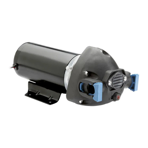
FLOJET R3B21 Series User manual

FLOJET

FLOJET R3B21 Series User manual
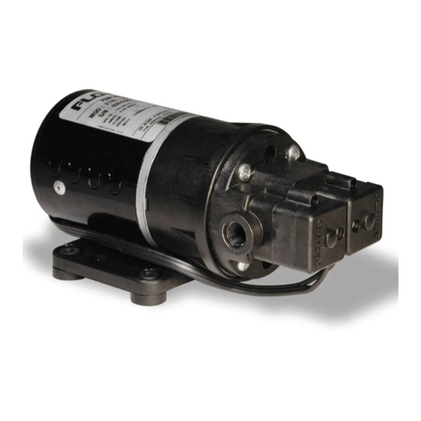
FLOJET 2125 Series User manual

FLOJET

FLOJET 2125 Series User manual
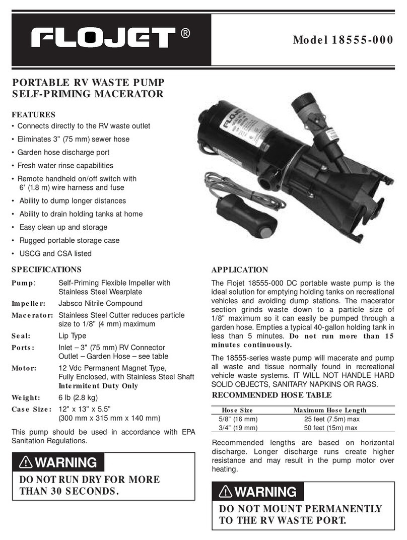
FLOJET 18555-000 User manual

FLOJET

FLOJET 18555-000 User manual

FLOJET N5000 Series Operation manual

FLOJET

FLOJET N5000 Series Operation manual
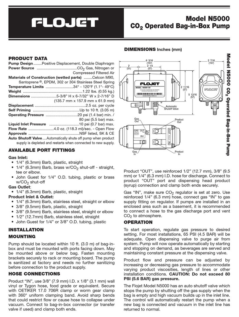
FLOJET N5000 User manual

FLOJET

FLOJET N5000 User manual
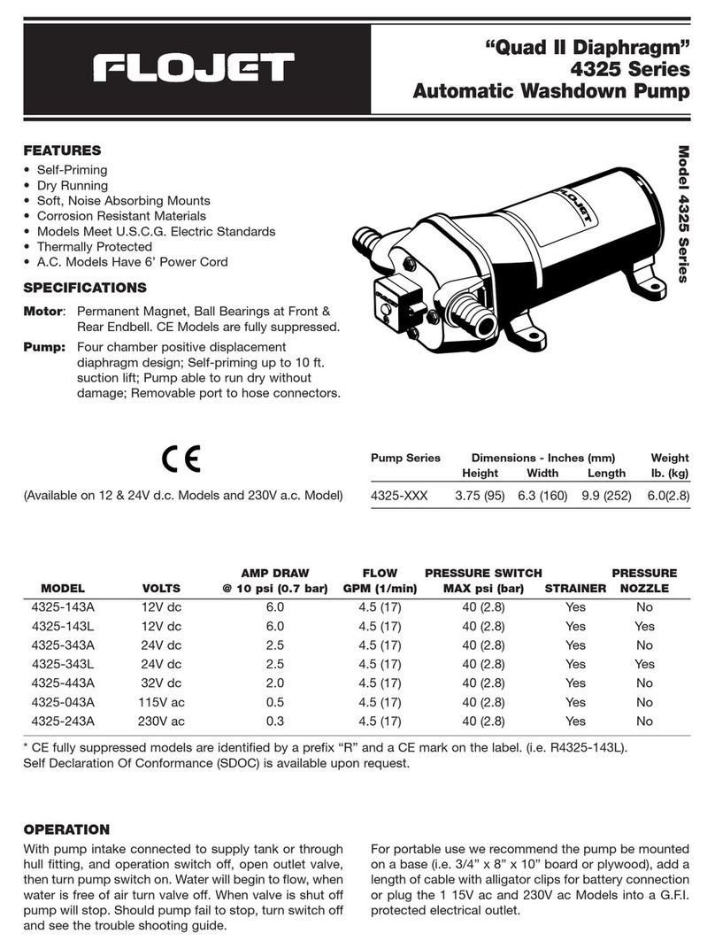
FLOJET 4325 Series User manual

FLOJET

FLOJET 4325 Series User manual
FLOJET G-57 Series Installation instructions

FLOJET

FLOJET G-57 Series Installation instructions

FLOJET 4105 Series User manual

FLOJET

FLOJET 4105 Series User manual

FLOJET 4300 Series User manual

FLOJET

FLOJET 4300 Series User manual
FLOJET quad II diaphragm 4125 series User manual
FLOJET

FLOJET quad II diaphragm 4125 series User manual

FLOJET R4515-743 User manual

FLOJET

FLOJET R4515-743 User manual

FLOJET G573 User manual

FLOJET

FLOJET G573 User manual

FLOJET G56 User manual

FLOJET

FLOJET G56 User manual

FLOJET R3526144 User manual

FLOJET

FLOJET R3526144 User manual

FLOJET BevJet Compact User manual

FLOJET

FLOJET BevJet Compact User manual
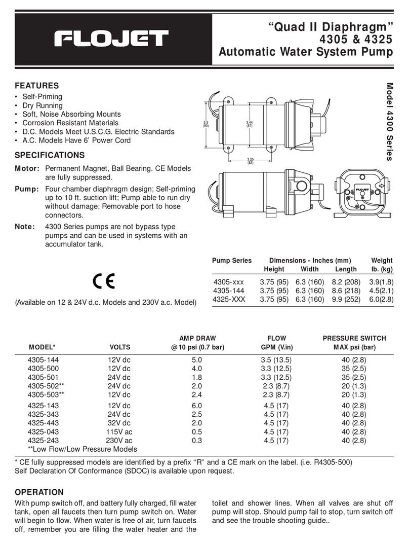
FLOJET 4305-144 User manual

FLOJET

FLOJET 4305-144 User manual

FLOJET N5100-010 Guide

FLOJET

FLOJET N5100-010 Guide

FLOJET N5100 Series Guide

FLOJET

FLOJET N5100 Series Guide

FLOJET 02840100A Operating and installation instructions

FLOJET

FLOJET 02840100A Operating and installation instructions

FLOJET 3426 series User manual

FLOJET

FLOJET 3426 series User manual

Popular Water Pump manuals by other brands
Sandpipper S05 Operating and service manual
Sandpipper

Sandpipper S05 Operating and service manual

MATO CMiNDTEK EP 100 operating instructions
MATO

MATO CMiNDTEK EP 100 operating instructions

Agilent Technologies TPS-flexy Quick Reference Assembly Guide

Agilent Technologies

Agilent Technologies TPS-flexy Quick Reference Assembly Guide

Ceco Sethco P90S quick start guide

Ceco

Ceco Sethco P90S quick start guide
Reefe RPS57E Exploded View & Instruction Manual
Reefe

Reefe RPS57E Exploded View & Instruction Manual

GORMAN-RUPP PUMPS T4B65-B Installation, operation, and maintenance manual with parts list

GORMAN-RUPP PUMPS

GORMAN-RUPP PUMPS T4B65-B Installation, operation, and maintenance manual with parts list

IWAKI AMERICA Walchem EWN-Y Quick start programming guide

IWAKI AMERICA

IWAKI AMERICA Walchem EWN-Y Quick start programming guide

pumpa BLUE LINE PMC1004P.1 manual

pumpa

pumpa BLUE LINE PMC1004P.1 manual
Nippon Oil Pump Cyclone Filter Pump User instruction manual
Nippon Oil Pump

Nippon Oil Pump Cyclone Filter Pump User instruction manual

GORMAN-RUPP SUPER T SERIES Installation, operation and maintenance manual
GORMAN-RUPP

GORMAN-RUPP SUPER T SERIES Installation, operation and maintenance manual

Dekker Maxima-K 1 Series Installation, operation and maintenance manual

Dekker

Dekker Maxima-K 1 Series Installation, operation and maintenance manual
AMT 3826-99 Specifications information and repair parts manual
AMT

AMT 3826-99 Specifications information and repair parts manual

Hilti DWP 10 operating instructions

Hilti

Hilti DWP 10 operating instructions
Danfoss 45 Frame K2 Series Service manual
Danfoss

Danfoss 45 Frame K2 Series Service manual

GORMAN-RUPP PUMPS GMS Series Installation, operation and maintenance manual

GORMAN-RUPP PUMPS

GORMAN-RUPP PUMPS GMS Series Installation, operation and maintenance manual
ESPANGO IPCR6 Installation and maintenance instructions
ESPANGO

ESPANGO IPCR6 Installation and maintenance instructions

Grundfos SCALA 2 Service instruction

Grundfos

Grundfos SCALA 2 Service instruction
SHUR-DRI SD-520C-T7-01 installation manual

SHUR-DRI

SHUR-DRI SD-520C-T7-01 installation manual

manuals.online logo
manuals.online logoBrands
  • About & Mission
  • Contact us
  • Privacy Policy
  • Terms and Conditions

Copyright 2025 Manuals.Online. All Rights Reserved.