manuals.online logo
Brands
  1. Home
  2. •
  3. Brands
  4. •
  5. FLOJET
  6. •
  7. Water Pump
  8. •
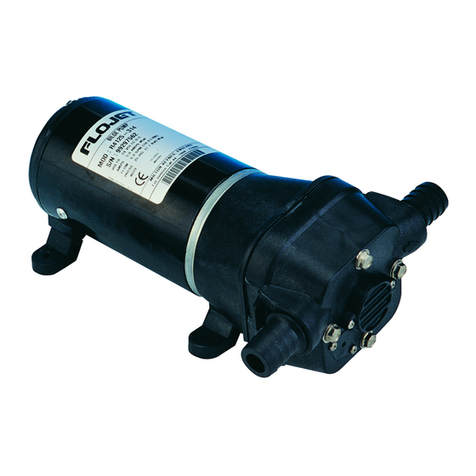
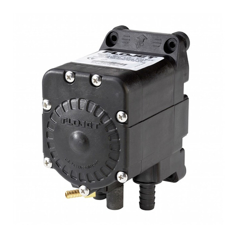
  9. FLOJET 2125 Series User manual

FLOJET 2125 Series User manual

Model 2125
Electric Beverage Pump
MOUNTING
• Ensure the area you have selected for installation is
dry, well ventilated, and has access to power.
• The suction side of the pump should be positioned so
that it is facing down. (See illustration below) This will
optimize the priming, and avoid cavitation from air in
the bag-in-box product.
• ideally the pump should be at the same level or just
below product.
• Position pump to desired area, secure mounting
screws through the rubber grommet in the baseplate
of pump. (See, illustration below)
HOSE CONNECTIONS
• Food grade Vinyl tygon tubing or equivalent with 3/8”
I.D. (8.9 mm) is recommended for both suction and
discharge.
• Total length of tubing run should not exceed 50’ (15.2 m)
to ensure sufficient pressure to brix the dispensing valve.
• The vertical lift of the, tubing run should not exceed
10” (3.0 m) within the 50’ (15.2 m) hose run.
• Use a #17.0 oetiker clamp or a worm gear clamp with
360° uniform clamping band.
• Avoid sharp, bends that could restrict flow especially
on suction side.
• After tubing installation is complete begin priming
sequence.
Model 2125 Electric Beverage Pump
2125 PUMP INSTALLATION ELECTRICAL
24 Volt AC Power - Wire pump as follows: Black wire
and white wire to 24 Volt power supply. Green wire to
safety ground.
115 Volt AC Power - Plug pump into standard 115 Volt
grounded electrical source or GFI.
230 Volt AC Power - Wire appropriate connector for
system. Green wire to safety ground.
OPERATION
The Model 2125 is a demand pump. The pump will
come on when dispensing valve is open and shut off
when valve is closed.
To start operation, open dispensing valve to purge air
from the system. Pump will now operate automatically
by starting and stopping on demand, as beverage is
served and maintain constant pressure, at dispensing
valve. The pump will shut off when beverage bag has
been depleted and sold out light will go on. The pump
will automatically reset and the light will go out when a
full bag is connected. The pump is equipped with an
automatic timer designed to shut the pump off after 3
minutes of continuous running. The timer is set at the
factory and needs no adjustment. To restart, push white
reset button on face of pump. To purge any air trapped
in the pump open Dispensing Valve and run pump until
all air is purged from pump and inlet lines.
System pressure and flow can be adjusted as follows:
Pressure control - The hexhead screw on face of pump
adjusts the pressure (See Fig. #3). The pump is set at 50
PSI (3.4 BAR) max. at the factory. To reduce pressure
turn screw counter clockwise with Alien wrench. To
increase, turn screw clockwise. Pressure can be
adjusted between a high of 50 PSI (3.4 BAR) to a low of
30 PSI (2.1 BAR).
The 2125 has an automatic sold out switch which stops
the pump when bag is empty and high vacuum builds
up in the inlet line. The sold out switch is set at 14 ± 2
in Hg. The sold out switch will automatically restart the
pump when a new bag is connected and vacuum in the
inlet line has returned to normal.
FIGURE 3
Discharge
Side
Suction
Side
Mounting
Screws
Oetiker
Clamp
Pressure
Adjustment
Sold Out
LIght
Plastic
Base Plate
Reset
SOLD OUT
Increase
Decrease
RESET F
L
O
W
FIGURE 1
Discharge
Side
The Pump Head
Can Be Rotated
In 90°Increments
90°
0°
Suction
Side
Mounting
Screws
FIGURE 1 Front View
PARTS LIST MODEL 2125 SERIES
4 56
1216 8
2 37 111 91011
1415
13
KEY PART NO. DESCRIPTION PUMP DASH NO.
1 02029-034A 115 VAC Motor 030, 501, 504, 505
02039-033A 230 VAC Motor 502, 503
02059-001A 24 VAC Motor 330
4 11028-102 Base Assy (3, 4 & 5) All 2125 S
13 20028-057 Valve Chmbr Kit STO All 2125 S
2 20115-122 Endbell/Brush Assy 030, 501, 504, 505
20115-123 Endbell/Brush Assy 330
20115-124 Endbell/Brush Assy 230, 502, 503
16 20131-001 P/H & Bearing Cvr Screws All 2125 S
6 20131-002 Baseplate Screws All 2125 S
5 20132-000 Grommets All 2125 S
3 20145-100 TIM 24 VAC Kit 330
20145-101 TIM 115 VAC Kit 030
20145-102 TIM 230 VAC Kit 230, 503
20177-100 TIM 115 VAC Kit 501, 504, 505
20177-101 TIM 230 VAC Kit 502
KEY PART NO. DESCRIPTION PUMP DASH NO.
15 20244-104 SW Cover 24 VAC Kit 330
20244-105 SW Cover 115 VAC Kit 030, 501, 504, 505
20244-106 SW Cover 230 VAC Kit 230, 502, 503
14 20316-016A U/Housing (50 PSI) 030, 230, 330
20316-033A U/Housing (45 PSI) 501, 502, 504
20316-034A U/Housing (50 PSI) 503
20316-047A U/Housing (45 PSI) 505
10 20428-100 Bearing Cover All 2125 S
9 21033-000 0 Cam/Bearing All 2125 S
21033-001 1 Cam/Bearing All 2125 S
11 21041-001 Inner/Outer Pistons All 2125 S
7 21131-000 Cam/Bearing Screws All 2125 S
12 21195-003 Dia/Pist Kit STO All 2125 S
8 91008-000 Cam/Bearing Set Screw All 2125 S
TROUBLE SHOOTING
1.Pulsating flow - pump cycling on and off:
• Restricted pump delivery. Check discharge lines, fittings, valves.
• Check motor speed and pressure adjustments.
2. Failure to prime - Motor operates, but no pump discharge:
• Empty product bag.
• Bag connector not fully engaged.
• 0obstruction in product discharge line or dispensing valve.
• Air leak in intake line.
• Punctured pump diaphragm.
• Defective pump check valve.
• Faulty pump.
• Leak or break in product inlet or discharge line.
3. Pump contInues to operate when product is “Sold Out”:
• Leak in suction line or faulty automatic shutoff.
• Punctured pump diaphragm.
• Discharge line leak.
• Insufficient voltage to pump.
• Defective pump check valve.
4. Low pressure at dispensing valve:
• Excessive line restriction due to undersize tubing or fittings.
• Check pressure adjustment.
• Check motor speed adjustment.
• Air leak at pump intake.
• Accumulation of debris inside pump and plumbing.
• Worn pump bearing (excessive noise).
• Punctured pump diaphragm.
• Defective motor. Defective pump check valve.
© Copyright 2001, ITT Industries Printed in U.S.A. All Rights Reserved Form: 81000-128 10/00
UNITED KINGDOM
Flojet, Unit 1, Avant Business Centre
Denbigh West Industrial Estate
Milton Keynes, Bucks, England MK1 1DL
Tel: 44 1908 370088
Fax: 44 1908 373731
U.S.A.
Flojet
20 Icon
Foothill Ranch, CA 92610-3000
Tel: (949) 859-4945
Fax: (949) 859-1153
LIMITED WARRANTY
FLOJET warrants this product to be free of defects in material and/or workmanship
for a period of one year after purchase by the customer from FLOJET. During this
one year period, FLOJET will at its option, at no charge to the customer, repair or
replace this product with a new or reconditioned product, but not remove or install,
in the event that it is found to be defective in material and/or workmanship.
This Limited Warranty does not include service to diagnose a claimed malfunction
in this product at any location other than at Flojet’s corporate head-quarters, nor to
repair damage due to improper installation, incompatibility with accessories not
manufactured by FLOJET, external electrical fault, accident, or misuse.
All other express and implied warranties for this product including the warranties of
merchantability and fitness for a particular purpose, are hereby disclaimed. The
product covered by this warranty is marketed and sold by FLOJET as a business
rather than consumer product. (Some jurisdictions do not allow the exclusion of
implied warranties nor limitations on how long an implied warranty lasts, so the
above limitations may not apply to you.)
If this product is not free of defect as warranted above, your sole and exclusive
remedy shall be repair or replacement as provided herein. In no event will FLOJET
be liable to customer or to any third party for any damages in excess of the
purchase price of the product. This limitation applies to damages of any kind
including any direct or indirect damages, lost profits, lost investment capital or
savings, or other special, incidental, tort or otherwise, or whether arising out of the
use or inability to use such product even if FLOJET has been advised of the
possibility of such damages or of any claim by any other party. (Some jurisdictions
do not allow the exclusion or limitation of incidental or consequential damages for
some products, so the above limitations or exclusions may not apply to you.)
This warranty gives you specific legal rights. You may also have other rights which
may vary from jurisdiction to jurisdiction.
5. Pump fails to restart automatically after bag replacement:
• Bag connector not fully engaged.
6. Pump fails to stop when dispensing valve is closed.
• Leak in discharge line. • Defective pump check valve.
• Empty product bag and • Insufficient voltage to pump.
• Faulty auto shutoff. • Speed control set to low.
• Faulty pump.
Other FLOJET Water Pump manuals

FLOJET N5000 Series Operation manual

FLOJET

FLOJET N5000 Series Operation manual

FLOJET 4105 Series User manual

FLOJET

FLOJET 4105 Series User manual

FLOJET 4300 Series User manual

FLOJET

FLOJET 4300 Series User manual

FLOJET G56 User manual

FLOJET

FLOJET G56 User manual

FLOJET R4515-743 User manual

FLOJET

FLOJET R4515-743 User manual

FLOJET G-57 Series Installation instructions

FLOJET

FLOJET G-57 Series Installation instructions

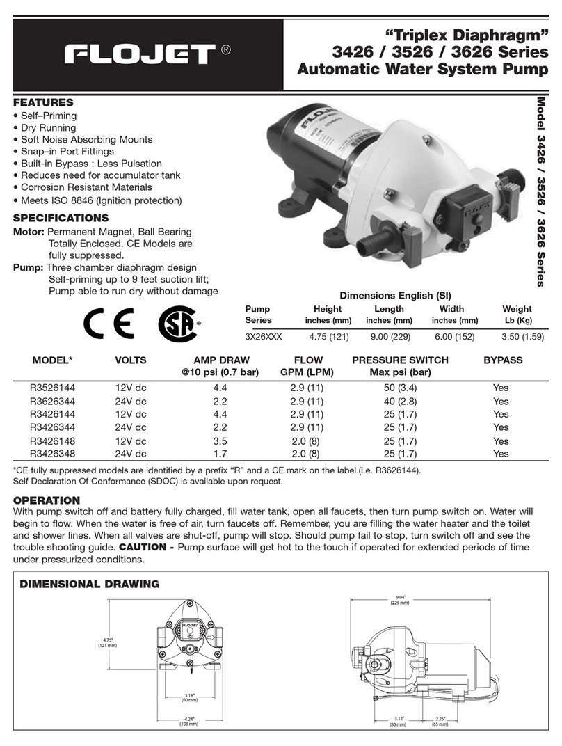
FLOJET Triplex Diaphragm 3426 Series User manual

FLOJET

FLOJET Triplex Diaphragm 3426 Series User manual

FLOJET N5100-010 Guide

FLOJET

FLOJET N5100-010 Guide

FLOJET 4305-144 User manual

FLOJET

FLOJET 4305-144 User manual

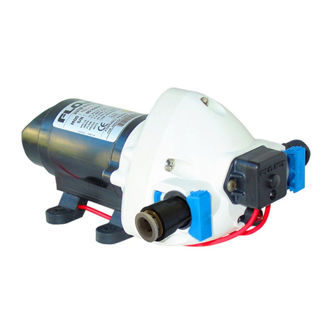
FLOJET R3526144 User manual

FLOJET

FLOJET R3526144 User manual

FLOJET BevJet Compact User manual

FLOJET

FLOJET BevJet Compact User manual

FLOJET N5100 Series Guide

FLOJET

FLOJET N5100 Series Guide

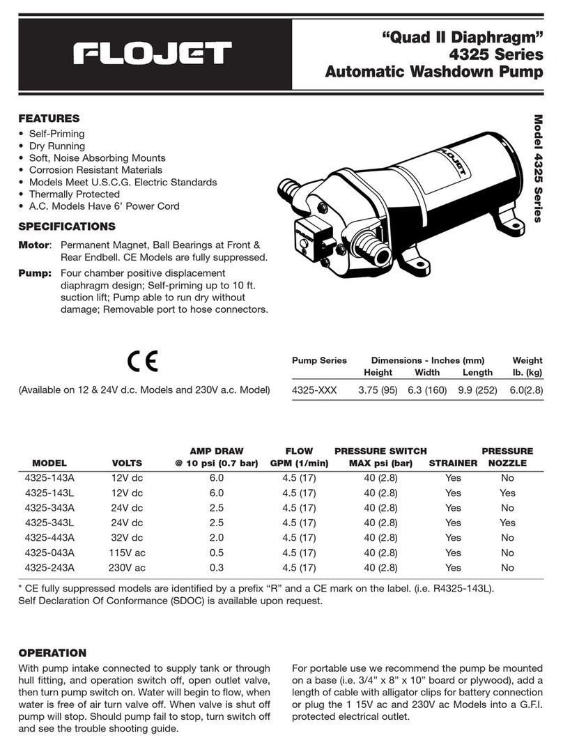
FLOJET 4325 Series User manual

FLOJET

FLOJET 4325 Series User manual

FLOJET 3426 series User manual

FLOJET

FLOJET 3426 series User manual

FLOJET 2100-12 User manual

FLOJET

FLOJET 2100-12 User manual

FLOJET quad II diaphragm 4125 series User manual

FLOJET

FLOJET quad II diaphragm 4125 series User manual

FLOJET N5000 User manual

FLOJET

FLOJET N5000 User manual

FLOJET G573 User manual

FLOJET

FLOJET G573 User manual

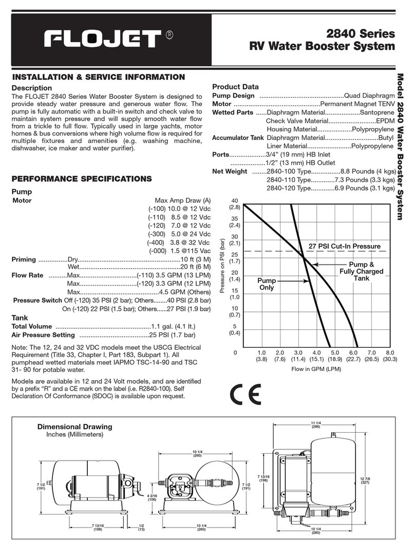
FLOJET 02840100A Operating and installation instructions

FLOJET

FLOJET 02840100A Operating and installation instructions

FLOJET G257 Series Guide

FLOJET

FLOJET G257 Series Guide

FLOJET 03526-144 User manual

FLOJET

FLOJET 03526-144 User manual

FLOJET R3B21 Series User manual

FLOJET

FLOJET R3B21 Series User manual

FLOJET G70C Series Owner's manual

FLOJET

FLOJET G70C Series Owner's manual

FLOJET 18555-000 User manual

FLOJET

FLOJET 18555-000 User manual

Popular Water Pump manuals by other brands

Pentair Fairbanks nijhuis 1820 Installation, operation and maintenance

Pentair

Pentair Fairbanks nijhuis 1820 Installation, operation and maintenance

Calpeda MGP Original operating instructions

Calpeda

Calpeda MGP Original operating instructions

Briggs & Stratton PROSERIES 205378GS Operator's manual

Briggs & Stratton

Briggs & Stratton PROSERIES 205378GS Operator's manual

Agilent Technologies TPS-compact X3580-64000 user manual

Agilent Technologies

Agilent Technologies TPS-compact X3580-64000 user manual

Ruris Aqua 1090 manual

Ruris

Ruris Aqua 1090 manual

Calpeda GQ Series Original operating instructions

Calpeda

Calpeda GQ Series Original operating instructions

Gardena 7000/C Operation instructions

Gardena

Gardena 7000/C Operation instructions

Pentair VERSAILLES Series manual

Pentair

Pentair VERSAILLES Series manual

Dover PSG ALL-FLO S100 Installation operation & maintenance

Dover

Dover PSG ALL-FLO S100 Installation operation & maintenance

DeatschWerks Mustang DW400 installation guide

DeatschWerks

DeatschWerks Mustang DW400 installation guide

Grundfos Fire DNF Installation and operating instructions

Grundfos

Grundfos Fire DNF Installation and operating instructions

Asymtek DV-8000 Series owner's manual

Asymtek

Asymtek DV-8000 Series owner's manual

Bestway 62167 owner's manual

Bestway

Bestway 62167 owner's manual

Wilo Atmos BST Installation and operating instructions

Wilo

Wilo Atmos BST Installation and operating instructions

vacuubrand BioChem-VacuuCenter BVC 21 Instructions for use

vacuubrand

vacuubrand BioChem-VacuuCenter BVC 21 Instructions for use

Jefferson Professional Tools & Equipment JEFSUBPIDW260-11 user manual

Jefferson Professional Tools & Equipment

Jefferson Professional Tools & Equipment JEFSUBPIDW260-11 user manual

Wayne 330102-001 Operating instructions and parts manual

Wayne

Wayne 330102-001 Operating instructions and parts manual

Simer 2975PC owner's manual

Simer

Simer 2975PC owner's manual

manuals.online logo
manuals.online logoBrands
  • About & Mission
  • Contact us
  • Privacy Policy
  • Terms and Conditions

Copyright 2025 Manuals.Online. All Rights Reserved.