Fnirsi DPOX180H User manual

二合一数字荧光示
波器 使用说明书
DPOX180H
2-in-1Digital Phosphor OscilloscopeInstruction Manual
Phosphor&zoom
SAVEP SAVEW MOVE ORIG
STO/RET MOD/OK
MENU AUTO
ME
AS
V
+
V
_
TR
IG
50
%
GEN ZOOM
H- H+ T
+
T
_
CH1 CH2


Product introduction 4
Warning 5
Notice 5
1.Main interface description 6
2.ZOOM interface description 8
3.Cursor interfacedescription 9
5.Signal generator interfacedescription 10
6.Clipping wave interface description 11
7.Key description 12
8.Operation guide 14
9.Common problems 19
10.Contact US 22
4.X-Y mode interface description 10
CATALOG

4

●When the two channels are used at the same time, the ground clips of the two probes
must be connected together. It is strictly forbidden to connect the ground clips of the
two probes to dierent electric potentials, especially the dierent potential terminals of
high-power device or 220V. Otherwise, the main board of the oscilloscope will be
burned, because the two channels are common ground, and connecting to dierent
potentials will cause a short circuit of the internal ground wire of the main board, which
isthe case for all oscilloscopes.
●The oscilloscope's BNC terminal input can tolerate up to 400V, and it is strictly forbidden
to input more than 400Vvoltage under the 1Xprobe switch.
●Charging must be charged with a separate charger. It is strictly forbidden to use the
power supply or USB of other currently tested devices, otherwise it may cause a short
circuit to the ground wire of the mainboard during the test and burn the mainboard.
●When measuring high-frequency and high-voltage signals, you must use 100Xprobes
(such as ultrasonic welding machines, ultrasonic cleaning machines, etc.) or even
1000X probes (such as high-voltage ends of high-frequency transformers, induction
cooker resonant coils, etc.)
Warning
Notice
The bandwidth of the 1 X probe gear of the accessory probe is 5 MHz, and the
bandwidth of the 10 X probe gear is 200 MHz. When measuring a frequency higher
than 5 MHz, you need to switch the probe to the 10 X gear, and the oscilloscope
should also be set to the 10 X gear. Otherwise the signal will be greatly attenuated,
as is the case with all oscilloscopes. Because the probe line of the oscilloscope itself
has a capacitance as high as 100~300 pF, which is a large capacitance for high-
frequency signals! The signal has been greatly attenuated when it reaches the input
end of the oscilloscope through the probe, and the equivalent bandwidth is 5 MHz.
Therefore, in order to match the hundreds of pF of the probe line, the input end of the
probe line isrst attenuated by 10 times (the switch is at 10 X), so that hundredsof pF
capacitors are just used for impedance matching. At this time, the bandwidth is 200
MHz. Note that only probes with a bandwidth of 200 MHz or above can be used.
5
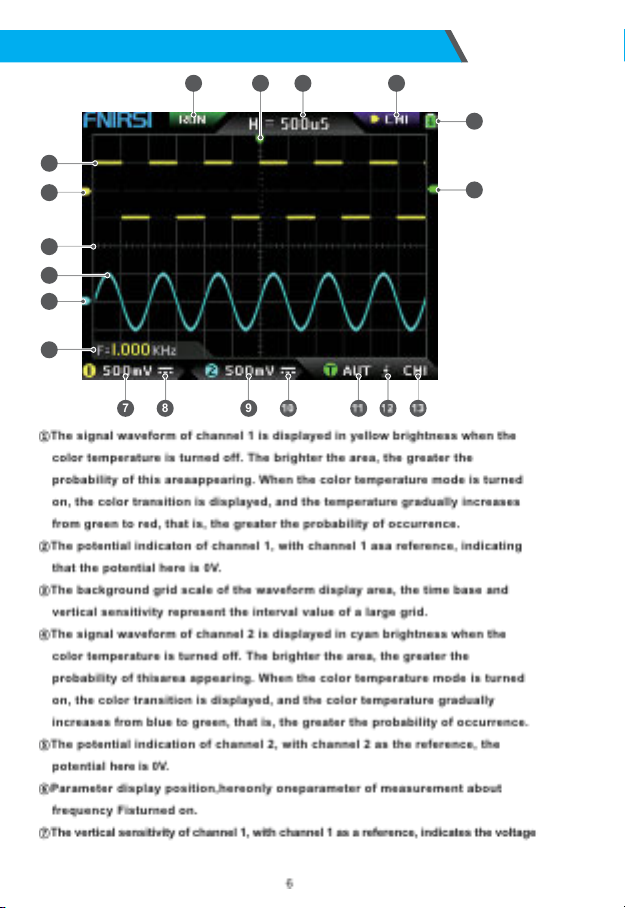
1.Main interface description
1
14
15
2
3
4
5
6
7
19 17 1618
8 9

interval represented by one large division in the vertical direction of the
background grid scale, and 500mVhere means that the voltage interval of one
large division in the vertical direction of the grid scale is 500 mV.
⑧The icon of the input coupling mode of channel 1. The upper part of the icon is
a horizontal line and the lower part is a dotted mark, which means DC coupling.
If it is a triangular waveform icon, it means AC coupling.
⑨Thevertical sensitivity of channel 2,with channel 2 as a reference,indicates the
voltage interval represented by one large division in the vertical direction of the
background grid scale, and 500 mV here means that the voltage interval of one
large division in the vertical direction of the grid scale is 500 mV.
⑩The input coupling mode icon of channel 2. The icon above isa horizontal line
and the dash mark below indicates DC coupling. If it is a triangle waveform icon,
it indicates AC coupling.
⑪Trigger mode ag, respectively AUT, SIG, NOR. AUT means Auto automatic trigger,
SIG means single trigger, NOR means Normal regular trigger.
⑫Trigger edge indicator icon, if the middle arrow points up, it means rising edge
trigger, if it pointsdown, it meansfalling edge trigger.
⑬Trigger signal source ag, CH1 meansuse channel 1 asthe trigger source signal
source, CH2 means use channel 2 as the trigger source signal source.
⑭Trigger level indicator, indicating that the level position of the selected trigger
signal source is set as the trigger threshold.
⑮Battery status icon, the green area indicates the remaining power, and if there is
an arrow in the middle, it meansit ischarging.
⑯Control selection sign. When the cursor function is turned off, there are two
choices of CH1 and CH2. When the cursor is turned on, there are three choices of
CH1 and CH2. When the cursor is turned on, there are three choices of CH1, CH2
and CSR. You can click the【 MOD/OK】button to switch. When CH1 is selected, it
meansthe up, down and V+ of the direction keys, and V- controls CH1. When CH2
is selected, it means the up, down and V+ of the direction buttons, and V- controls
CH2. When CSR is selected, it means that all direction keys only control the
cursor.
⑰Time base position, indicating the time interval represented by a large grid in
the horizontal direction of the background grid scale, where H = 500 uS means
that the time interval of a large grid in the horizontal direction of the grid scale
is500uS.
⑱Arrow indicating the trigger horizontal position,which means that the trigger
threshold condition has just been reached at thispoint.
⑲Sampling running and pause flag, RUN means sampling, STOP means stop
sampling.
7
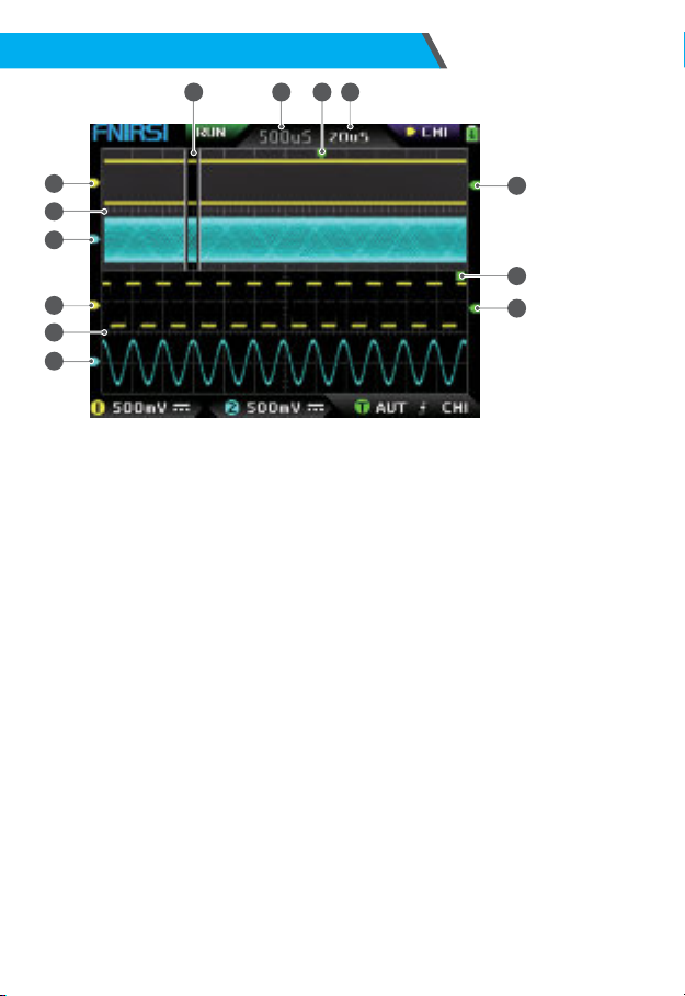
2.ZOOM interface description
2
5
7
9
8
1
3
4
6
13 1012 11
①Under the main time base, the reference potential indicator arrow of channel 1,
with channel 1 asa reference, indicates that the potential here is 0 V.
②Main time base, in the upper half of the display area, all vertical dimensions are
reduced to half of the original.
③Under the main time base, the reference potential indicator arrow of channel 2,
with channel 2 as a reference, indicates that the potential here is 0 V.
④Under the ZOOM timebase, the reference potential indicator arrow of channel 1,
taking channel 1 as a reference, indicatesthat the potential here is 0 V.
⑤ZOOM time base, in the lower half of the display area, all vertical dimensions
are reduced to half of the original.
⑥Under the ZOOM time base, the reference potential indicator arrow of channel
2, with channel 2 asa reference, indicates that the potential here is 0 V.
⑦Under the ZOOM time base, the indicator arrow of the trigger potential indicates
that the potential of the selected trigger signal source is set as the trigger
threshold.
⑧After zooming in from the selected part of the main time base, the X position of
the trigger level in the main time base is mapped to the Xposition in the ZOOM
time base.
⑨Under themain timebase,theindicator arrow of thetrigger potential indicates that
the potential of the selected trigger signal source isset asthe trigger threshold.
⑩ZOOM time base gear, indicating the time interval represented by a large grid in
the horizontal direction of the grid scale of the ZOOMtime base.
⑪The trigger horizontal position indicator arrow of the main time base, indicating
that the trigger condition has just been reached at this position.
8

3.Cursor interface description
⑫Main time base position, indicating the time interval represented by a large grid
in the horizontal direction of the grid scale of the main time base.
⑬The ZOOM time base is mapped to the enlarged area of the main time base,
indicating that the waveform in this area is enlarged and mapped to the ZOOM
time base.
①Measurement data of cursor measurement, including equivalent frequency F,
time length T, potential difference V1 of channel 1 and potential difference V2 of
channel 2.
②The upper boundary line measured by the vertical cursor.
③The lower boundary line measured by the vertical cursor.
④Active cursor indication sign, the arrow keys control the cursor selected by S,
under the CSR control selection, press the【 AUTO】 to switch the current Sactive
cursor.
⑤Right boundary line of horizontal cursor measurement.
⑥Left boundary line of horizontal cursor measurement.
2
3
1
4
6 5
9
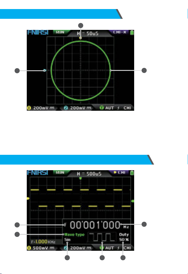
①The reference potential indicator of channel 2, with channel 2 as the reference,
indicating that the potential here is0V.
②An X-Yclosed curve graph composed of the signal of channel 1 as Xand the
signal of channel 2 asY, with digital fluorescent display.
③The indicator of the reference potential of channel 1, with channel 1 as a
reference, indicating that the potential here is0V.
4.X-Y mode interface description
12
3
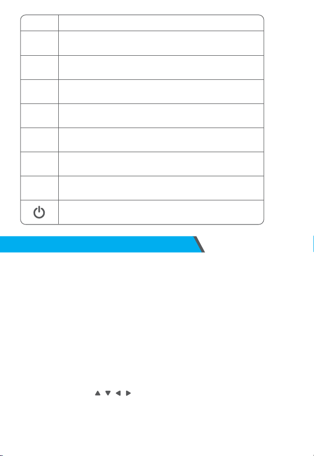
5.Signal generator interface description
1
2
6
3 4 5
10

①Frequency symbol, F is the abbreviation of Frequency, you can switch and control
F, Wave type and Duty through the【 MOD/OK】key, and the active state is green.
②Wave type mark, you can switch control F and Wave type and Duty through the
【MOD/OK】key, and the active state is green.
③The name of the type of waveform signal, including 14 kinds of function signals
and 1 kind of chopping signal.
④Thumbnail image of the waveform signal, showing 3 cycles of the waveform.
⑤Theduty cycle of the waveform signal can only be operated when the signal is a
square wave, and it is only valid for square waves.
⑥The frequency value of the output signal, the step is1Hz, the sinewave can reach
up to 20 MHz, and the other waveform can reach up to 10 MHz.
①The left boundary line of the clipping wave.
②Period mark,theintercepted signal isthesignal from theleft boundary lineto
theright boundary line, asa period.
③Active cursor indication mark, the arrow keys control the cursor selected by S, in
the CSRcontrol selection mode, press the【 AUTO】 to switch the current Sactive
cursor.
④The right boundary line of the clipping wave.
⑤The signal of CH1/CH2 can be switched by pressing【 Up】and【 Down】, CH1 indicates
the signal of channel 1, and CH2 indicatesthe signal of channel 2.
⑥Vertical potential mark, used to refer to the amplitude value of the currently
intercept- ed waveform.
6.Clipping wave interface description
4
3
1
6 5
2
11

One-click save screen capture, click thisbutton, the system will
automatically capture the display content of the entire screen and save
it asa BMP image file to store in the local disk.
Slightly adjustment/Roughly adjustment switch button,change the
movement speed, such as waveform movement and cursor movement,
etc., The movement speed of coarse adjustment is10 times higher.
Save the waveform with one button, click this button and the
system will automatically save the data of the opened channel asa
WAV waveform file and store it on the local disk.
SAVEP
SAVEW
MOVE
Button Function
7.Key description
12

STO/RET
MOD/OK
MENU
AUTO
MEAS
V+
V-
H+
H-
T+
Button Function
ORIG
One-key return to the center button. After clicking this button, all the
indicator arrows will return to the middle position, that is, CH1, CH2,
trigger X, and trigger Y will return to the middle position.
This button has two functions of switching control selection and conrmation.
When all menus are closed, this button is used to switch among CH1, CH2, and CSR
three control options. When the menu is opened, this button is for conrmation.
This button has two functions of pausing sampling and returning to the menu.
When all menus are closed, this button switches between running and
pausing sampling. When the menu is opened, it is used for returning.
Open/exit button of the main menu, all system settings are in this main
menu, exit means to exit to the waveform main interface, and return
means to return to theprevious menu.
The vertical zoom-out button of the waveform, its voltage scale value will
increase, click this button, the vertical direction of the waveform of the
selected channel will be reduced by 2~2.5 times.
The horizontal zoom-in button of the waveform, its timebase value
will decrease, click thisbutton,the horizontal direction of the
waveform of the selected channel will be enlarged by 2~2.5 times.
It isused to increase the trigger level, increase the trigger threshold
voltage, and the trigger indicator arrow will move upward.
Waveform horizontal reduction button, its time base value will
increase, click this button,the horizontal direction of the waveform of
the selected channel will be reduced by 2~2.5 times.
One-key automatic adjustment, click this button and the system will
automatically adjust the parameters to make the waveform reach the best
display state..
Parameter measurement shortcut key, this key isused to quickly open the
menu and automatically locate the parameter setting bar.
The vertical zoom-in button of the waveform, its voltage scale value will
decrease, click this button, the vertical direction of the waveform of the
selected channel will be zoomed in by 2~2.5 times.
Up arrow key, mainly used to move the waveform, move the cursor, switch
menu items, etc.
Down arrow key, mainly used to move the waveform, move the cursor,
switch menu items, etc.
Left arrow key, mainly used to move the waveform, move the cursor,
adjust parameter values, etc.
Right arrow key, mainly used to move the waveform, move the cursor,
adjust parameter values, etc.
13
T-
TRIG
50%
CH1
CH2
GEN
ZOOM
Button Function
It is used to reduce the trigger level, reduce the trigger threshold
voltage, and the trigger indicator arrow will move down.
In the off state, click this button to turn on the power, and in the
power on state,click this button to turn off the power.
Onekey to automatically set the trigger level to a suitable position,
and its ratio will be adaptively adjusted to 25% or 50% or 75%.
Trigger control setting shortcut key, this key is used to quickly open
the menu and automatically locate the trigger control setting bar.
Shortcut key for control setting of channel 1, this key is used to
quickly open the menu and automatically locateto the control setting
column of CH1.
Shortcut key for for control setting of channel 2, thiskey is used to
quickly open the menu and automatically locate the control setting
column of CH2.
Turn on or off the DDS signal generator control interface.
Turn on or off the zoom time base function of ZOOM.
8.Operation guide
Turn on: In the power-o state, click the power button to start the system.
Turn o: In the power-on state, click the power button to shut down.
Zoom waveform: First observe the control selection sign in the upper left corner of the
screen, and observe whether the content indicated by the arrow pointing to the right
isthe channel that needs to be zoomed currently, CH1 means channel 1, CH2 means
channel 2, if not, you need to click【 MOD/OK】button to switch to the current desired
channel, such as CH1 or CH2, when the two are consistent, then click【 H+】【H-】to
adjust the zoom in the horizontal direction, and【 V+】【V-】to perform vertical zoom
adjustment.
Moving waveform: First look at the control selection sign, and observe whether the
content indicated by the arrow pointing to the right isthe channel that needsto be moved
currently.If it ismovingin the horizontal direction, you only need to switch to CH1or CH2.
If it is moving in the vertical direction , you can only select the channel you want to move,
and then click the button to move.
Automatically adjust the waveform: the horizontal adjustment of automatic adjustment
is to adjust according to the channel selected by the trigger rst, and the vertical
adjustment is independent adjustment. Click【 AUTO】to automatically adjust the
parameters of each channel to achieve the best display state of the waveform.
14

Set the movement adjustment speed: Click【 MOVE】to set the movement speed of the
current direction key, which is divided into coarse adjustment and ne adjustment. The
movement speed of coarse adjustment is10 timesthat of ne adjustment.
Return the waveform to the midpoint position: Click【 ORIG】to return the waveform to
the midpoint position, that is, the vertical reference potential/trigger horizontal position/
trigger vertical position all return to the middle position.
Running and Pausing Sampling: Click【STO/RET】 to switch between running and
pausing sampling.
Switching control selection: Click【 MOD/OK】to switch between CH1 and CH2, when
the cursor is turned on, a CSR selection will be added.
Parameter measurement: Click【 MEAS】, a menu will pop up, use and to
locate the channel to be measured in the selection bar, and then click【 MOD/OK, 12
kinds of measurement parameters will pop up, and then click Click【 MOD/OK】 to
select the parameters that need to bemeasured at present, you can choose multiple,
and then click 【MENU】to exit the menu.
Manual cursor measurement: Click【 MENU】, a menu will appear, use and to
the Cursor measure column, and then click【 MOD/OK】, and use to the Horizontal
measure or Vertical measure column, and then click【 MOD/OK】to turn on or o the
horizontal or vertical cursor, and then click【 MENU】to exit the menu. After exiting
the menu, the control selection mode will automatically switch to the CSR cursor
control mode , in the CSRcontrol mode, click【 AUTO】to switch the active cursor,
there will be an S mark next to the active cursor, indicating that the cursor is
controlled by the current direction keyboard, and you can also click【 MOD/OK】to
switch the control to CH1 or CH2 to move the waveform.
Turn on the ZOOM time base: Click【 ZOOM】to turn on the ZOOM time base. At this
time, there will be two time bases. The upper half is the main time base, and the lower
half is the ZOOM zoom time base.
The zoom ratio is 2~1000 times. Among them, the【 H+】,【 H-】and buttons
can only control the parameters of the ZOOM time base, that is, the horizontal
direction can only control the ZOOM time base, and the horizontal direction
parameters of the main time base are stopped before ZOOM is turned to on status.
The waveform under ZOOM is the enlarged map of the waveform in the unobstructed
area of the main time base.
Set the trigger mode: Click【 TRIG】, a menu will pop up, use to the Trigger mode
column, and then click【MOD/OK】 to select the current trigger mode. Auto means
automatic trigger, Single means single trigger, Normal means normal trigger, and then
click【 MENU】to exit the menu.
Set the trigger edge: Click【 TRIG】, a menu will pop up, use to the Trigger edge
column, and then click【 MOD/OK】to switch to Rising or Falling. Rising means rising
edge triggering, Falling means falling edge trigger, and then click【 MENU】to exit the
menu.
15

Set the trigger channel: Click【 TRIG】, a menu will pop up, use to the Trigger
channel column, then click【 MOD/OK】to switch to CH1 or CH2, and then click
【 MENU】 exit menu.
Adjust the trigger level: Directly press【 T+】【 T-】to adjust the green trigger electric
level arrow up and down.
Set the trigger electric level to 50%: The trigger level will automatically analyze the
signal and automatically set it to 25% or 50% or 75%. For example, a square wave
signal with a dead zone or a multi-tone signal cannot be set to 50%. Click【 50%】and
the trigger electric level can be set to the appropriate proportional position of the
signal of the selected trigger channel.
Set trigger high-frequency suppression: Click【 TRIG】, a menu will pop up, use and
to the HF rejection column, and then click【 MOD/OK】to select the strength of the
current trigger suppression required. There are 3 ranks in total. The greater the
signal noise, the stronger the trigger suppression is required, and then click【 MENU】
to exit the menu.
Open the control panel of the signal generator: Click【 GEN】to open the parameter
control panel of the signal generator, click【 MOD/OK】 to switch the waveform type,
frequency and duty cycle control.
Set the signal type of the signal generator: Click【 GEN】to open the parameter control
panel of the signal generator, click【 MOD/OK】 to switch the green to the Wave type
column, and then click to switch the waveform type , and the
corresponding thumbnails will be displayed on the right, where the Custom type is
the clipping signal set by the user.
Set the frequency of the signal generator: Click【 GEN】to open the parameter control
panel of the signal generator, click【 MOD/OK】to switch the green to the F column,
and then click to locate the desired setting Click to increase or decrease
the value.
Set the duty cycle of the signal generator: The duty cycle parameter is only valid
when the waveform type is square wave, click【 GEN】to open the parameter control
panel of the signal generator, click【 MOD/OK】to switch the green to Duty column, and
then press to decrease or increase the value of the duty cycle.
Capture waveform signal asoutput: Click【 MENU】, a menu will pop up, use and
to locate the selection bar to the Capture output column, and then click【 MOD/OK】,
two left and right cursors will appear in the display area.The left cursor is the left
border of the interception, and the right cursor is the right border of the
interception. The control selection mode will betemporarily set to CSR mode and
cannot be changed.Click 【AUTO】to switch the active cursor. There will be an S
mark next to the active cursor, indicating the current direction keyboard controls the
cursor, press to move the active cursor, click to switch the intercepted
signal source to CH1 or CH2, click 【MOD/OK】to save the current clipping data. The
waveform within the cursor range is a cycle waveform, and the control selection
mode will be restored to CH1 or CH2.
15

Set the clipping signal to be output: Click【 MENU】, a menu will pop up, use and
to locate the selection bar to the Data browser column, then click【 MOD/OK】,
and use and to the selection bar to the Capture browser column, and then
click 【MOD/OK】to enter the waveform browser to browse all the stored clipped
signals. One page can display 3X3 thumbnails, and there will be 4 control bars at
the bottom of the screen. Among them, Select corresponds to【 SAVEP】, Delete
corresponds to【 SAVEW】, Last page corresponds to【MOVE】, and Next page
corresponds to【ORIG】. Use the direction keys to set the blue selection area to
the waveform position that needs to be used asthesignal source,and then click
【 MOD/OK】to set thesignal astheclipped output signal, and there will be a yellow
"Set" mark in the upper left corner.
Save screenshot: Click【 SAVEP】to save the current screenshot as a BMP image le
to the local disk, and a total of 90 imagescan be stored.
Save waveform: Click【 SAVEW】to save the waveform data WAV le of the currently
opened channel to the local disk, and a total of 250 sets of waveform data can be
saved.
View the saved picture: Click【 MENU】, a menu will pop up, use and to
the Data browser column, and then click【 MOD/OK】, and use and to the Picture
browser column, then click【 MOD/OK】to enter the picture browser. One page can
display 4X4 thumbnails.The full name of the file is displayed under each
thumbnail, and therewill be 4 controls at the bottom of the screen. Column, where
Select corresponds to【 SAVEP】, Delete corresponds to【SAVEW】, Last page
corresponds to【MOVE】, and Next page corresponds to【 ORIG】. Use the direction
keys to set the green selection area to the position of the picture you want to view,
and then click【 MOD/OK】to view the picture in full screen. In the full-screen view
interface, you can use the direction keys to view the previous or next picture.
Click【MENU】 to return to the thumbnail interface of the previous level, or click
【 SAVEW】to delete the picture le.
View the saved waveform: Click【 MENU】, a menu will pop up, use and to the
Data browser column, and then click【 MOD/OK】, and use and to the
Waveform browser column, then click【 MOD/OK】to enter the waveform browser.
One page can display 3X3 thumbnails. The full name of the file is displayed under
each thumbnail. There will be 4 controls at the bottom of the screen. column, where
Select corresponds to【 SAVEP】, Delete corresponds to【SAVEW】, Last page
corresponds to【MOVE】, and Next page corresponds to【 ORIG】. Set the green
selection area to the waveform position to be viewed through the direction keyboard,
and then click【 MOD/OK】, the system automati- cally returns to the main
interface, pauses sampling, and loads the current waveform data, which is the
same as after pausing sampling , you can move, zoom, ZOOM, X-Y, measure, take a
screenshot, etc.
Open or close the channel: Click【 CH1】or【 CH2】, a menu will pop up, use to
the Channel enable column, and then click【 MOD/OK】 to open or close the channel
waveform display, click【 MENU】to exit the menu.
Set the probe magnication: Click【 CH1】or【 CH2】, a menu will pop up, use and
to the Probe gear column, and then click【 MOD/OK】to pop up options, select the
17

required settings. Then click【 MOD/OK】to set the probe magnication to 1X or 10X
or 100X, and then click【 MENU】to exit the menu.
Set the input coupling mode: Click【 CH1】or【 CH2】, a menu will pop up, use and
to the Coupling mode column, and then click【 MOD/OK】to switch the coupling
mode to DCDCor AC, and click【 MENU】to exit the menu.
Display simple FFT waveform: Click【 CH1】or【 CH2】, a menu will pop up, use and
to the FFT display column, and then click【 MOD/OK】to turn on or o the FFT
display , and then click【 MENU】to exit the menu.
Set the 20MHz hardware bandwidth limit: Click【 CH1】or【 CH2】, a menu will pop up,
use to the Hard bandwidth limit column, and then click【 MOD/OK】to
open or close 20M hardware bandwidth limit, then click【 MENU】to exit the menu.
Set automatic bandwidth limit: Click【 MENU】, a menu will pop up, use and
to the Function settings column, and then click【 MOD/OK】, and use【 Up】to the Auto
bandwidth limit column, and then click【 MOD/OK】, a menu will pop up, and select
the level to be limited through and . There are 6 levelsin total. As the level
increases, the limit strength gradually increases. The specific bandwidth value will
be displayed in the upper right corner of the display area Auto BW = XHz, and then
click【 MENU】to exit the menu.
Baseline calibration of the channel: First pull out the probe and USB cable, click
【MENU】,amenu will pop up,use to the Function settings column, and then
click 【MOD/OK】and use to the Baseline calibration column, then click【 MOD/
OK】, a menu will pop up, make sure all connections have been unplugged, and
then click 【MOD/OK】to calibrate.
System calibration: System calibration refers to the calibration of the vertical
system, including offset calibration, balance calibration, baseline calibration, and
the calibration time is relatively long. First pull out the probe and USB cable, click
【 MENU】, a menu will up, use to the Function settings column, and then
click【 MOD/OK】, press to the System calibration column, and then click
【 MOD/OK】, a menu will pop up, make sure that all connections have been
unplugged, and then click【 MOD/OK】 to calibrate.
Adjust the brightnessof the waveform: Click【 MENU】, a menu will pop up, use and
to position the selection bar to the Function settings column, and then click
【MOD/OK】, and use and to the Waveform brightness column, press to
decrease the brightness of the waveform, press to increase the brightness of
the waveform, it isgenerally recommended to set it to 50%,and then click【 MENU】
to exit the menu.
Color temperature display mode:Click【 MENU】, a menu will pop up, use and
to the Function settings column, and then click【 MOD/OK】, and use and to
the Color temperature column, click【 MOD/OK】to enable or disable the color
temperature display mode, and then click【 MENU】to exit the menu.
18

X-Y time base mode: Click【 MENU】, a menu will pop up, select the column to Function
settings through , then click【 MOD/OK】, select the column through Locate
the X-Y curve option column, click【 MOD/OK】 to enable or disable the X-Y time base
mode, and then click【MENU】to exit the menu.
Scrolling time base mode: Click【 H-】continuously to increase the time base value until
it reaches H=100mS, and the time base mode automatically enters the scrolling mode.
Open or close the Background grid scale: Click【 MENU】, a menu will pop up, use
and to the System settings column, and then click【 MOD/OK】, press and
to the Background grid display column, then click【 MOD/OK】to start or shutdown
the grid scale, and then click【 MENU】to exit the menu.
Set the transparency of the menu window: Click【 MENU】, a menu will pop up, use
and to the System settings column, and then click【 MOD/OK】, and us and
to the Transparent menus column, press to decrease transparency, press
to increase transparency, and then click【 MENU】to exit the menu.
Save the current conguration asthe default conguration:Click【 MENU】, a menu
will pop up, use and to the System settings column, and then click【 MOD/OK】,
and use and to the Save current conguration column, and then click
【 MOD/OK】, a prompt will pop up, and then click【 MOD/OK】to save the current
conguration as the default conguration for system power-on and then click
【 MENU】to exit menu.
USB connection to the computer to share pictures: First connect the oscilloscope
to the computer with a Type-C USB cable, click【 MENU】, a menu will pop up, use
to the System settings column, and then click【 MOD】/OK】, use to the USB
sharing mode column, and then click【 MOD/OK】to enter the USB sharing mode.
Set automatic shutdown: Click【 MENU】, a menu will pop up, use and to the
System settingscolumn, and then click【 MOD/OK】, and use and to the
Automatic shutdown column, and then click【 MOD/OK】to pop up a menu, then
select the time that needs to be scheduled, and then click【 MOD/OK】to set the
time for scheduled shutdown, and then click【 MENU】to exit the menu.
Restore factory settings: Click【 MENU】, a menu will pop up, use and to the
System settings column, and then click【 MOD/OK】, and use and to the
Factory settings column, and then click【 MOD/OK】to pop up the selection, if you are
sure to restore the factory settings, select YES and conrm to restore the factory settings.
Storage space formatting: Click【 MENU】, a menu will pop up, use and
to the System settings column, and then click【 MOD/OK】, and use navigate
to the Disk formatting column, and then click【 MOD/OK】, a warning will pop up.
After conrming that formatting is required, select YES and conrm to delete all
stored data.
Why can't turn on the device after receiving it ?
Answer: The power-on operation isto click the power button. If it still cannot be turned
on, it may be that the battery is out of power. Use the attached USB to charge, the power
9.Common problems
19

button will display red, and you can start the device at thistime.
Why isthere no waveform in the test, only a straight baseline on the screen ?
Answer: Please check whether the pause is pressed, if not, press the [AUTO] button, if not, it
may be that the signal source has no signal output, or the probe line is short-cir- cuited or
open-circuited, please check the probe with a multimeter and whether the signal source
isnormal.
Why is the voltage value zero ?
Answer: Please adjust the vertical sensitivity and time base (sampling rate), or press
[AUTO], at least a clear and complete cycle waveform is displayed on thescreen, and the top
and bottom of the waveform must be completely displayed on the screen without clipping.
At this moment, the voltage value is correct.
Why is the frequency value zero ?
Answer: First, you need to make sure that the trigger mode is Auto. If it is still 0 in in Auto
mode, you need to press the [AUTO] button once. After at least one clear and complete
cycle waveform is displayed on the screen, and the waveform needs to be triggered ( The
green arrow indicates that the position is between the top and bottom of the waveform, xed
and not shaking), and the data of the frequency value iscorrect.
Why is the duty cycle zero ?
Answer: First, you need to make sure that the trigger mode is Auto. If it is still 0 in Auto
mode,it may bethat thetrigger isnot adjusted between the wave forms.After the trigger line is
adjusted between the waveforms, the waveform will be xed, and the screen needs to The
duty cycle data is correct only after at least one clear cycle waveform is displayed.
Why are AC coupled and DC coupled waveforms the same ?
Answer: If the input signal is a symmetrical AC signal (such as 220V for household use), the
waveform is the same whether it is AC coupling or DC coupling. If it is an asymmetrical AC
signal or a DC pulsating signal, then the waveform will only move up and down when the
coupling is switched.
Why does the waveform jump up and down when testing the signal, but can't see the
waveform but only see multiple lines jumping up and down ?
Answer: Set the trigger mode to Auto, and then press the [AUTO] button once. If the
problem persists, it may be that the ground clip on the probe is not grounded, or the ground
clip end of the probe is broken. Please use a multimeter to check whether the probe
isnormal.
Why does the test waveform keep shaking from side to side and cannot be xed ?
Answer: You need to adjust the trigger voltage, that is, the green arrow on the right. You
need to adjust the green indicator arrow between the top and bottom of the waveform so
that the waveform can be triggered. First, check whether the trigger signal source is the
channel of the current shaking waveform signal. After setting, click【50%】.
Why can't capture sudden pulse waveforms or digital logic signals?
Answer: Adjust the trigger mode to Single trigger mode, then adjust the trigger voltage,
20
Other manuals for DPOX180H
1
Table of contents
Other Fnirsi Test Equipment manuals

Fnirsi
Fnirsi 1013D Instruction sheet

Fnirsi
Fnirsi FNB48P User manual

Fnirsi
Fnirsi DSO-TC2 User manual

Fnirsi
Fnirsi FNB48 User manual

Fnirsi
Fnirsi FNB38 User manual

Fnirsi
Fnirsi FNIRSI-1C15 User manual

Fnirsi
Fnirsi DSO152 User manual

Fnirsi
Fnirsi FNC88 User manual

Fnirsi
Fnirsi DPOX180H User manual

Fnirsi
Fnirsi SG-003A User manual


Popular Test Equipment manuals by other brands

Amada
Amada MM-315B Operation manual

Edision
Edision MULTI-FINDER user guide

Valhalla Scientific
Valhalla Scientific 4314KV Operation manual

Leagend
Leagend BA102 user manual

HYDAC FILTER SYSTEMS
HYDAC FILTER SYSTEMS CTM-SC 3 Series Operating and maintenance instructions

Keysight
Keysight 4000 X-Series Advanced training guide


