Fnirsi 1013D Instruction sheet
Product
instructions
FNIRSI-1013D
Two
channel
plate
oscilloscope
YOUR
GOOD
TEST
TOOL
Product
introduction
FNIRSI-1013D
is
a
full-featured,
highly
practical,
cost-effective
dual-channel
flat-panel
oscilloscope
launched
by
FNIRSI
for
the
maintenance
and
R
&
D
industry;
this
oscillo-
scope
has
a
real-time
sampling
rate
of
1GSa
/
s
and
an
analog
bandwidth
of
100MHz
*
2.
With
complete
trigger
function
(single
/
normal
/
automatic),
it
can
be
used
freely
for
periodic
analog
signals
or
non-periodic
digital
signals;
the
built-in
high-voltage
protection
module
can
tolerate
a
continuous
voltage
of
up
to
400V.
Oscilloscope
burnout
accident
caused
by
the
probe
being
turned
to
the
10X
position.
Large
time
base
scroll
mode
can
monitor
slow
level
changes;
Equipped
with
highly
efficient
one-key
AUTO,
which
can
display
the
measured
waveform
without
tedious
adjust-
ments;
the
display
is
equipped
with
a
7-inch
800
*
480
resolution
high-definition
LCD
LCD
screen,
and
the
operation
method
is
capacitor
Screen
touch
+
gesture
operation,
extremely
convenient;
cursor
measurement
function,
you
do
not
need
to
read
the
background
scale
unit
and
quantity
when
manually
reading
the
amplitude
and
frequency
parameters,
and
you
can
directly
get
the
peak,
peak
and
frequency
without
conversion;
extremely
convenient
screenshot
And
waveform
storage
function,
built-in
1GB
storage
space,
can
store
up
to
1000
screenshots
+
1000
sets
of
waveform
data,
the
storage
process
is
simple
and
fast,
save
the
current
waveform
anytime,
anywhere
with
a
single
touch,
no
cumbersome
prompts
and
choices,
keep
calm
The
current
data
is
saved
in
the
place,
which
is
very
convenient;
the
powerful
waveform
picture
manag-
er
supports
thumbnail
browsing,
viewing,
detailed
viewing,
page
turning,
deletion
and
waveform
zooming
in,
zooming
out,
moving,
etc.
to
facilitate
secondary
analysis.
The
fuselage
is
equipped
with
a
USB
interface,
which
can
be
connected
to
a
computer
to
share
its
screenshots
with
the
computer,
which
is
convenient
for
secondary
analysis;
Li
Shayu's
graphic
display
function
can
be
used
to
determine
the
amplitude,
frequency,
and
phase
contrast
of
two
groups
of
signals;
Analysis
of
the
harmonic
components
of
the
signal;
built-in
6000mah
high-quality
lithium
battery,
which
can
last
for
4
hours
on
a
full
charge,
and
can
be
used
while
charging
like
a
notebook
The
bandwidth
of
the
1X
probe
file
is
5MHz,
and
the
bandwidth
of
the
10X
probe
file
is
100MHz.
When
measuring
higher
than
5MHZz,
you
need
to
turn
the
switch
on
the
probe
handle
to
the
10X
position,
and
the
oscilloscope
must
be
set
to
the
10X
position
.
Otherwise
the
signal
will
be
greatly
attenuated,
as
is
the
case
with
all
oscillo-
scopes.
Because
the
probe
line
of
the
oscilloscope
itself
has
a
capacitance
of
up
to
100
—
300pF,
it
is
a
very
large
capacitance
for
high-frequency
signals!
The
signal
has
been
greatly
attenuated
through
the
probe
to
the
input
of
the
oscilloscope,
and
the
equiva-
lent
bandwidth
is
5MHz.
Therefore,
in
order
to
match
the
hundreds
of
pF
of
the
probe
line,
the
input
of
the
probe
line
is
attenuated
by
10
times
(the
switch
is
in
the
10X
range).
A
few
hundred
pF
capacitors
are
just
used
for
impedance
matching.
At
this
time,
the
bandwidth
is
100MHz.
Note
that
only
probes
with
a
bandwidth
of
100MHz
or
higher
can
be
used.
ZOuS/div
vPp
:1.960
EU
vP
:1.0zv
Freq
:
20.Oktiz
VPP
:1.940
Frea
:
5.00KHz
RUN
VPP
:1.96U
VP
:1.020
Freq
:
20.0RHz
VPP
:1.94U
Freq
:5.00RHz
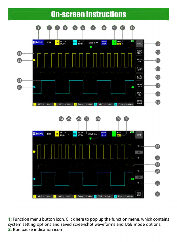
1:
Function
menu
button
icon.
Click
here
to
pop
up
the
function
menu,
which
contains
system
setting
options
and
saved
screenshot
waveforms
and
USB
mode
options.
2:
Run
pause
indication
icon

3:
Channel
1
position
indication
means
that
the
parameters
near
this
block
area
are
all
parameters
of
Channel
1.
Clicking
this
area
will
pop
up
the
Channel
1
control
bar
4:
Probe
magnification
of
channel
1,
divided
into
1X,
10X,
100X
three
options
5:
Channel
2
position
indication
means
that
the
parameters
near
this
block
area
are
the
parameters
of
Channel
2.
Clicking
this
area
will
pop
up
the
Channel
2
control
bar
6:
Probe
magnification
of
channel
2,
divided
into
1X,
10X,
100X
three
options
7:
System
time
base
refers
to
the
length
of
time
represented
by
a
large
grid
in
the
horizontal
direction,
which
is
determined
by
the
sampling
rate.
The
larger
the
time
base,
the
slower
the
sampling
rate,
and
vice
versa.
8:
The
movement
speed
under
the
gesture
movement
operation.
[Move
coarse
adjustment]
means
fast
movement,
[Move
fine
adjustment]
means
slow
movement.
9:
Trigger
indication
icon,
which
means
that
the
parameters
near
this
block
area
are
all
trigger
related
parameters.
Clicking
this
area
will
pop
up
the
trigger
control
bar
10:
trigger
channel,
divided
into
CH1,
CH2
options
11:
Battery
remaining
power
indicator
icon,
green
block
indicates
remaining
power
12:
Main
interface
control
bar
function
switch
button,
click
this
button
to
switch
between
2
types
of
button
bar
13:
Run
pause
button,
click
this
button
to
switch
between
running
and
pause
14:
One-button
automatic
adjustment
button.
Clicking
this
button
will
automatically
identify
the
signal
and
set
the
system
to
the
best
parameters
to
display
the
waveform.
15:
Time
cursor
switch
button,
click
this
button
to
turn
the
cursor
measurement
function
on
and
off
16:
Voltage
cursor
switch
button,
click
this
button
to
turn
cursor
measurement
on
and
off
17:
Measurement
parameter
selection
function.
Click
this
button
to
pop
up
the
parameter
selection
bar.
Click
the
parameter
in
the
selection
bar
to
open
the
parame-
ter
display.
18:
One-click
screenshot
button,
click
this
button
to
take
a
screenshot
of
the
entire
screen
and
automatically
save
it
to
the
internal
storage
space
19:
One-click
waveform
save
button.
Clicking
this
button
will
save
all
waveform
data
of
2
channels
to
the
internal
storage
space.
20:
The
arrow
indicating
the
baseline
position
of
channel
2
is
the
position
of
OV
potential
21:
Waveform
data
of
channel
2
22:
Channel
1
baseline
position
indicating
arrow,
which
is
the
position
of
OV
potential
23:
Waveform
data
of
channel
1
24:
Input
coupling
indicator
icon
of
channel
1,
there
are
two
options
of
DC
and
AC,
DC
means
DC
coupling,
AC
means
AC
coupling
25:
The
vertical
sensitivity
indicator
of
channel
1
refers
to
the
voltage
represented
by
a
large
division
in
the
vertical
direction.
26:
Input
coupling
indicator
of
channel
2.
There
are
two
options:
DC
and
AC.
DC
means
DC
coupling
and
AC
means
AC
coupling.
27:
The
vertical
sensitivity
indicator
of
channel
2
refers
to
the
voltage
represented
by
a
large
grid
in
the
vertical
direction.

28:
Trigger
X
position
indicating
arrow,
which
refers
to
the
trigger
point
here
29:
Trigger
mode
indication
icon,
divided
into
Auto,
Single,
Normal;
Auto
is
automatic
trigger,
Sinle
is
single
trigger,
Normal
is
normal
trigger
30:
trigger
edge
indication
icon,
the
arrow
points
up
to
the
rising
edge
to
trigger,
the
arrow
points
down
to
the
falling
edge
to
trigger
31:
Channel
1
vertical
sensitivity
increase
button,
that
is,
zoom
in
vertically.
Clicking
this
button
will
zoom
in
the
vertical
direction,
that
is,
stretch
vertically.
32:
Channel
1
vertical
sensitivity
reduction
button,
that
is,
the
vertical
direction
is
reduced.
Click
this
button
to
reduce
the
waveform
in
the
vertical
direction,
that
is,
vertically.
33:
trigger
voltage
indication
icon,
that
is,
the
trigger
threshold
34:
Channel
2
vertical
sensitivity
increase
button,
that
is,
zoom
in
vertically.
Click
this
button
to
zoom
in
the
vertical
direction,
that
is,
stretch
vertically.
35:
Channel
2
vertical
sensitivity
reduction
button,
that
is,
the
vertical
direction
is
reduced.
Clicking
this
button
waveform
will
be
reduced
in
the
vertical
direction,
that
is,
vertically
reduced.
36:
50%
trigger
button
refers
to
setting
the
trigger
voltage
to
the
middle
position
of
the
waveform
amplitude.
Note
that
it
cannot
be
used
for
PWM
waveforms
with
dead
time.
This
type
of
waveform
requires
the
trigger
arrows
to
be
set
to
both
sides
of
the
waveform.
1:
System
function
menu
key
area,
click
this
area
to
pop
up
system
function
and
setting
menu
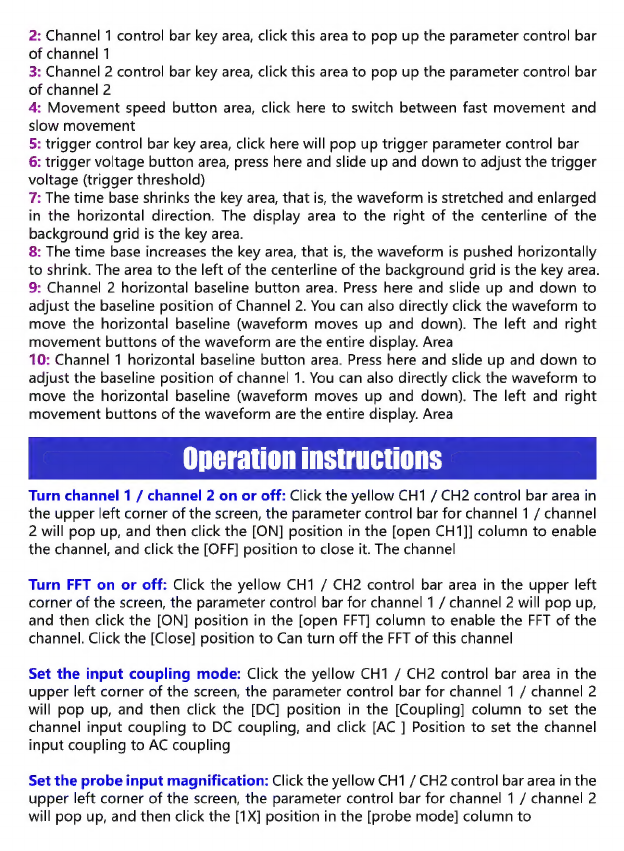
2:
Channel
1
control
bar
key
area,
click
this
area
to
pop
up
the
parameter
control
bar
of
channel
1
3:
Channel
2
control
bar
key
area,
click
this
area
to
pop
up
the
parameter
control
bar
of
channel
2
4:
Movement
speed
button
area,
click
here
to
switch
between
fast
movement
and
slow
movement
5:
trigger
control
bar
key
area,
click
here
will
pop
up
trigger
parameter
control
bar
6:
trigger
voltage
button
area,
press
here
and
slide
up
and
down
to
adjust
the
trigger
voltage
(trigger
threshold)
7:
The
time
base
shrinks
the
key
area,
that
is,
the
waveform
is
stretched
and
enlarged
in
the
horizontal
direction.
The
display
area
to
the
right
of
the
centerline
of
the
background
grid
is
the
key
area.
8:
The
time base
increases
the
key
area,
that
is,
the
waveform
is
pushed
horizontally
to
shrink.
The
area
to
the
left
of
the
centerline
of
the
background
grid
is
the
key
area.
9:
Channel
2
horizontal
baseline
button
area.
Press
here
and
slide
up
and
down
to
adjust
the
baseline
position
of
Channel
2.
You
can
also
directly
click
the
waveform
to
move
the
horizontal
baseline
(waveform
moves
up
and
down).
The
left
and
right
movement
buttons
of
the
waveform
are
the
entire
display.
Area
10:
Channel
1
horizontal
baseline
button
area.
Press
here
and
slide
up
and
down
to
adjust
the
baseline
position
of
channel
1.
You
can
also
directly
click
the
waveform
to
move
the
horizontal
baseline
(waveform
moves
up
and
down).
The
left
and
right
movement
buttons
of
the
waveform
are
the
entire
display.
Area
Operation
instructions
Turn
channel
1
/
channel
2
on
or
off:
Click
the
yellow
CH1
/
CH2
control
bar
area
in
the
upper
left
corner
of
the
screen,
the
parameter
control
bar
for
channel
1
/
channel
2
will
pop
up,
and
then
click
the
[ON]
position
in
the
[open
CH1]]
column
to
enable
the
channel,
and
click
the
[OFF]
position
to
close
it.
The
channel
Turn
FFT
on
or
off:
Click
the
yellow
CH1
/
CH2
control
bar
area
in
the
upper
left
corner
of
the
screen,
the
parameter
control
bar
for
channel
1
/
channel
2
will
pop
up,
and
then
click
the
[ON]
position
in
the
[open
FFT]
column
to
enable
the
FFT
of
the
channel.
Click
the
[Close]
position
to
Can
turn
off
the
FFT
of
this
channel
Set
the
input
coupling
mode:
Click
the
yellow
CH1
/
CH2
control
bar
area
in
the
upper
left
corner
of
the
screen,
the
parameter
control
bar
for
channel
1
/
channel
2
will
pop
up,
and
then
click
the
[DC]
position
in
the
[Coupling]
column
to
set
the
channel
input
coupling
to
DC
coupling,
and
click
[AC
]
Position
to
set
the
channel
input
coupling
to
AC
coupling
Set
the
probe
input
magnification:
Click
the
yellow
CH1
/
CH2
control
bar
area
in
the
upper
left
corner
of
the
screen,
the
parameter
control
bar
for
channel
1
/
channel
2
will
pop
up,
and
then
click
the
[1X]
position
in
the
[probe
mode]
column
to
set
the
input
magnification
of
the
channel
to
1X,
Click
[10X]
to
set
the
channel
input
magnification
to
10X,
click
[100X]
to
set
the
channel
input
magnification
to
100X
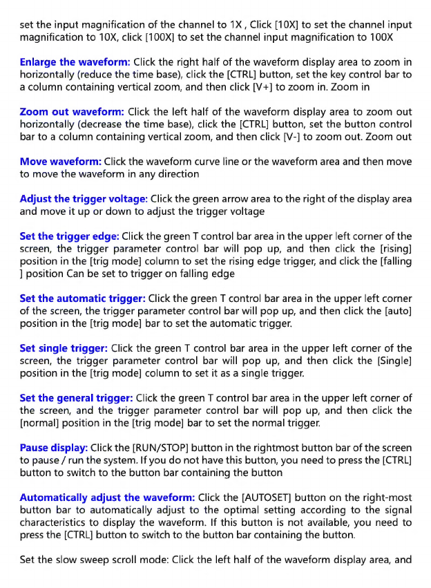
Enlarge
the
waveform:
Click
the
right
half
of
the
waveform
display
area
to
zoom
in
horizontally
(reduce
the
time
base),
click
the
[CTRL]
button,
set
the
key
control
bar
to
a
column
containing
vertical
zoom,
and
then
click
[V+]
to
zoom
in.
Zoom
in
Zoom
out
waveform:
Click
the
left
half
of
the
waveform
display
area
to
zoom
out
horizontally
(decrease
the
time
base),
click
the
[CTRL]
button,
set
the
button
control
bar
to
a
column
containing
vertical
zoom,
and
then
click
[V-]
to
zoom
out.
Zoom
out
Move
waveform:
Click
the
waveform
curve
line
or
the
waveform
area
and
then
move
to
move
the
waveform
in
any
direction
Adjust
the
trigger
voltage:
Click
the
green
arrow
area
to
the
right
of
the
display
area
and
move
it
up
or
down
to
adjust
the
trigger
voltage
Set
the
trigger
edge:
Click
the
green
T
control
bar
area
in
the
upper
left
corner
of
the
screen,
the
trigger
parameter
control
bar
will
pop
up,
and
then
click
the
[rising]
position
in
the
[trig
mode]
column
to
set
the
rising
edge
trigger,
and
click
the
[falling
]
position
Can
be
set
to
trigger
on
falling
edge
Set
the
automatic
trigger:
Click
the
green
T
control
bar
area
in
the
upper
left
corner
of
the
screen,
the
trigger
parameter
control
bar
will
pop
up,
and
then
click
the
[auto]
position
in
the
[trig
mode]
bar
to
set
the
automatic
trigger.
Set
single
trigger:
Click
the
green
T
control
bar
area
in
the
upper
left
corner
of
the
screen,
the
trigger
parameter
control
bar
will
pop
up,
and
then
click
the
[Single]
position
in
the
[trig
mode]
column
to
set
it
as
a
single
trigger.
Set
the
general
trigger:
Click
the
green
T
control
bar
area
in
the
upper
left
corner
of
the
screen,
and
the
trigger
parameter
control
bar
will
pop
up,
and
then
click
the
[normal]
position
in
the
[trig
mode]
bar
to
set
the
normal
trigger.
Pause
display:
Click
the
[RUN/STOP]
button
in
the
rightmost
button
bar
of
the
screen
to
pause
/
run
the
system.
If
you
do
not
have
this
button,
you
need
to
press
the
[CTRL]
button
to
switch
to
the
button
bar
containing
the
button
Automatically
adjust
the
waveform:
Click
the
[AUTOSET]
button
on
the
right-most
button
bar
to
automatically
adjust
to
the
optimal
setting
according
to
the
signal
characteristics
to
display
the
waveform.
If
this
button
is
not
available,
you
need
to
press
the
[CTRL]
button
to
switch
to
the
button
bar
containing
the
button.
Set
the
slow
sweep
scroll
mode:
Click
the
left
half
of
the
waveform
display
area,
and
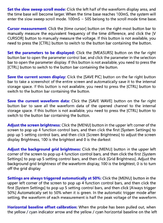
Set
the
slow
sweep
scroll
mode:
Click
the
left
half
of
the
waveform
display
area,
and
the
time
base
will
become
larger.
When
the
time
base
reaches
100mS,
the
system
will
enter
the
slow
sweep
scroll
mode.
100mS
>
50S
belong
to
the
scroll
mode
time
base.
Cursor
measurement:
Click
the
[time
cursor]
button
on
the
right-most
button
bar
to
manually
measure
the
equivalent
frequency
of
the
time
difference,
and
click
the
[V
CURSOR]
button
to
manually
measure
the
voltage.
If
this
button
is
not
available,
you
need
to
press
the
[CTRL]
button
to
switch
to
the
button
bar
containing
the
button.
Set
the
parameters
to
be
displayed:
Click
the
[MEASURS]
button
on
the
far
right
button
bar
to
open
the
parameter
control
bar,
and
click
the
parameter
in
the
selection
bar
to
open
the
parameter
display.
If
this
button
is
not
available,
you
need
to
press
the
[CTRL]
button
to
switch
to
the
button
bar
containing
the
button.
Save
the
current
screen
display:
Click
the
[SAVE
PIC]
button
on
the
far
right
button
bar
to
take
a
screenshot
of
the
entire
screen
and
automatically
save
it
to
the
internal
storage
space.
If
this
button
is
not
available,
you
need
to
press
the
[CTRL]
button
to
switch
to
the
button
bar
containing
the
button.
Save
the
current
waveform
data:
Click
the
[SAVE
WAVE]
button
on
the
far
right
button
bar
to
save
all
the
waveform
data
of
the
opened
channel
to
the
internal
storage
space.
If
this
button
is
not
available,
you
need
to
press
the
[CTRL]
button
to
switch
to
the
button
bar
containing
the
button.
Adjust
the
screen
brightness:
Click
the
[MENU]
button
in
the
upper
left
corner
of
the
screen
to
pop
up 4
function
control
bars,
and
then
click
the
first
[System
Settings]
to
pop
up
5
setting
control
bars,
and
then
click
[Screen
Brightness]
to
adjust
the
screen
display
Brightness,
100
is
the
brightest
and
0
is
the
darkest
Adjust
the
background
grid
brightness:
Click
the
[MENU]
button
in
the
upper
left
corner
of
the
screen
to
pop
up
4
function
control
bars,
and
then
click
the
first
[System
Settings]
to
pop
up
5
setting
control
bars,
and
then
click
[Grid
Brightness].
Adjust
the
background
grid
brightness
of
the
waveform
display,
100
is
the
brightest,
0
is
to
turn
off
the
grid
display
Settings
are
always
triggered
automatically
at
50%:
Click
the
[MENU]
button
in
the
upper
left
corner
of
the
screen
to
pop
up
4
function
control
bars,
and
then
click
the
first
[System
Settings]
to
pop
up
5
setting
control
bars,
and
then
click
[Always
trigger
50%]
Automatically
set
to
50%
when
it
is
green.
In
the
automatic
trigger
mode
after
setting,
the
waveform
of
each
measurement
is
half
the
peak
voltage
of
the
waveform.
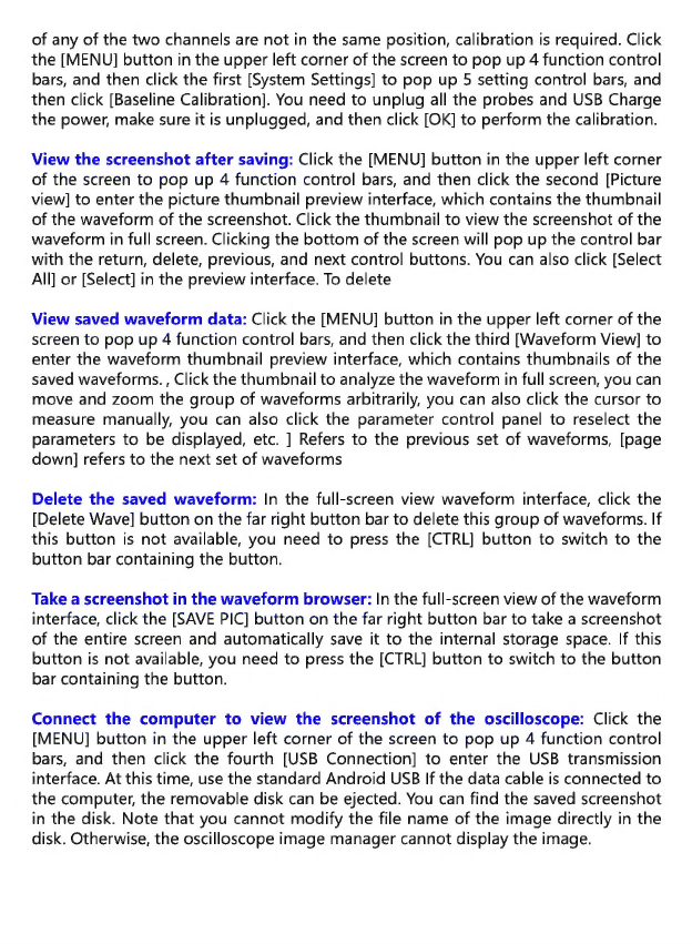
Horizontal
baseline
offset
calibration:
When
the
probe
has
been
pulled
out,
when
the
yellow
/
cyan
indicator
arrow
and
the
yellow
/
cyan
horizontal
baseline
on
the
left
of
any
of
the
two
channels
are
not
in
the
same
position,
calibration
is
required.
Click
the
[MENU]
button
in
the
upper
left
corner
of
the
screen
to
pop
up 4
function
control
bars,
and
then
click
the
first
[System
Settings]
to
pop
up
5
setting
control
bars,
and
then
click
[Baseline
Calibration].
You
need
to
unplug
all
the
probes
and
USB
Charge
the
power,
make
sure
it
is
unplugged,
and
then
click
[OK]
to
perform
the
calibration.
View
the
screenshot
after
saving:
Click
the
[MENU]
button
in
the
upper
left
corner
of
the
screen
to
pop
up
4
function
control
bars,
and
then
click
the
second
[Picture
view]
to
enter
the
picture
thumbnail
preview
interface,
which
contains
the
thumbnail
of
the
waveform
of
the
screenshot.
Click
the
thumbnail
to
view
the
screenshot
of
the
waveform
in
full
screen.
Clicking
the
bottom
of
the
screen
will
pop
up
the
control
bar
with
the
return,
delete,
previous,
and
next
control
buttons.
You
can
also
click
[Select
All]
or
[Select]
in
the
preview
interface.
To
delete
View
saved
waveform
data:
Click
the
[MENU]
button
in
the
upper
left
corner
of
the
screen
to
pop
up 4
function
control
bars,
and
then
click
the
third
[Waveform
View]
to
enter
the
waveform
thumbnail
preview
interface,
which
contains
thumbnails
of
the
saved
waveforms.,
Click
the
thumbnail
to
analyze
the
waveform
in
full
screen,
you
can
move
and
zoom
the
group
of
waveforms
arbitrarily,
you
can
also
click
the
cursor
to
measure
manually,
you
can
also
click
the
parameter
control
panel
to
reselect
the
parameters
to
be
displayed,
etc.
]
Refers
to
the
previous
set
of
waveforms,
[page
down]
refers
to
the
next
set
of
waveforms
Delete
the
saved
waveform:
In
the
full-screen
view
waveform
interface,
click
the
[Delete
Wave]
button
on
the
far
right
button
bar
to
delete
this
group
of
waveforms.
If
this
button
is
not
available,
you
need
to
press
the
[CTRL]
button
to
switch
to
the
button
bar
containing
the
button.
Take
a
screenshot
in
the
waveform
browser:
In
the
full-screen
view
of
the
waveform
interface,
click
the
[SAVE
PIC]
button
on
the
far
right
button
bar
to
take
a
screenshot
of
the
entire
screen
and
automatically
save
it
to
the
internal
storage
space.
If
this
button
is
not
available,
you
need
to
press
the
[CTRL]
button
to
switch
to
the
button
bar
containing
the
button.
Connect
the
computer
to
view
the
screenshot
of
the
oscilloscope:
Click
the
[MENU]
button
in
the
upper
left
corner
of
the
screen
to
pop
up 4
function
control
bars,
and
then
click
the
fourth
[USB
Connection]
to
enter
the
USB
transmission
interface.
At
this
time,
use
the
standard
Android
USB
If
the
data
cable
is
connected
to
the
computer,
the
removable
disk
can
be
ejected.
You
can
find
the
saved
screenshot
in
the
disk.
Note
that
you
cannot
modify
the
file
name
of
the
image
directly
in
the
disk.
Otherwise,
the
oscilloscope
image
manager
cannot
display
the
image.
Analysis
of
common
problems
1:
Why
can't
I
turn
on
the
phone
after
receiving
it?
A:
Maybe
after
the
final
test
is
completed,
the
tester
forgets
to
shut
down
and
puts
it
in
the
inventory
until
it
runs
out.
After
receiving
the
goods,
it
runs
out
of
power.
Please
use
USB
for
half
an
hour
before
powering
on.
Do
not
use
computer
USB
for
charging.
Computer
USB
If
the
power
is
too
low,
you
will
be
dissatisfied.
Use
the
original
charger.
2:
Why
is
there
no
waveform
in
the
test,
and
there
is
only
one
line
on
the
screen?
Answer:
Please
check
whether
the
pause
has
been
pressed.
If
not,
press
the
[Auto
Adjust]
button
once.
If
not,
it
may
be
that
the
signal
source
does
not
have
a
signal
output,
or
the
probe
wire
is
short-circuited
or
disconnected.
Please
check
with
a
multimeter.
Whether
the
probe
and
signal
source
are
normal
3:
Why
is
the
voltage
value
data
0?
Answer:
Please
adjust
the
vertical
sensitivity
and
time
base
(sampling
rate),
or
press
the
[AUTOSET]
screen
to
display
at
least
a
clear
and
complete
periodic
waveform,
and
the
top
and
bottom
of
the
waveform
should
be
completely
displayed
on
the
screen,
without
cutting
the
top.
Voltage
data
is
correct
4:
Why
is
the
frequency
value
data
0?
Answer:
First
of
all,
you
need
to
make
sure
that
the
trigger
mode
is
Auto.
If
it
is
still
O
in
Auto
mode,
you
need
to
press
the
[AUTOSET]
button
once.
At
least
one
clear
and
complete
periodic
waveform
is
displayed
on
the
screen,
and
the
waveform
is
to
be
triggered.
(The
green
arrow
indicates
that
the
position
is
between
the
top
and
bottom
of
the
waveform.
It
is
fixed
and
does
not
shake.)
The
data
of
the
frequency
value
is
correct.
5:
Why
is
the
duty
cycle
0?
Answer:
First
of
all,
you
need
to
ensure
that
the
trigger
mode
is
Auto.
If
it
is
still
O
in
Auto
mode,
the
trigger
may
not
be
adjusted
between
the
waveforms.
After
the
trigger
line
is
adjusted
between
the
waveforms,
the
waveform
will
be
fixed.
The
duty
cycle
data
is
correct
after
at
least
1
clear
periodic
waveform
is
displayed
6:
Why
are
the
AC
coupled
and
DC
coupled
waveforms
the
same?
Answer:
If
the
input
signal
is
a
symmetrical
AC
signal
(signal
output
by
the
signal
generator),
the
waveform
is
the
same
whether
it
is
AC
coupling
or
DC
coupling.
If
it
is
an
asymmetric
AC
signal
or
a
DC
pulsating
signal,
the
waveform
is
only
when
the
coupling
is
switched.
Will
move
up
and
down
7:
Why
does
the
waveform
jump
up
and
down
when
I
test
the
signal?
Ica
n’
t
see
any
waveform
but
only
see
multiple
lines
jumping
up
and
down?
Answer:
Set
the
trigger
mode
to
Auto,
and
then
press
the
[AUTOSET]
button
once.
If
it
is
not
resolved,
the
probe
on
the
probe
may
not
be
grounded,
or
the
probe
end
of
the
probe
may
be
disconnected.
Please
use
a
multimeter
to
check
whether
the
probe
is
normal.
8:
Why
does
the
waveform
of
the
test
shake
from
side
to
side
and
cannot
be
fixed?
Answer:
You
need
to
adjust
the
trigger
voltage,
that
is,
the
green
arrow
on
the
right.
Press
and
hold
the
green
trigger
arrow
on
the
right
and
move
it
up
and
down.
You
need
to
adjust
the
green
indicator
arrow
between
the
upper
and
lower
waveforms.
The
waveform
is
triggered
and
fixed,
or
you
enter
the
setting.
Menu
turns
on
"Auto
50%"
9:
Why
can't
Il
capture
the
sudden
pulse
waveform
or
digital
logic
signal?
Answer:
Adjust
the
trigger
mode
to
“normal”
or
“single”
,
and
then
adjust
the
trigger
voltage,
time
base,
and
vertical
sensitivity.
10:
Why
is
there
no
waveform
when
measuring
a
battery
or
other
DC
voltage?
Answer:
The
battery
voltage
signal
is
a
stable
DC
signal
and
has
no
curve
waveform.
In
the
DC
coupling
mode,
and
then
adjust
the
vertical
sensitivity,
an
upward
or
downward
offset
straight
line
waveform
will
appear.
If
it
is
AC
coupling,
no
matter
what
No
waveform
adjustment
11:
Why
the
charge
is
not
full?
Answer:
It
may
be
using
a
laptop
or
USB
charging
below
2A.
The
USB
output
power
of
the
laptop
is
too
small
to
be
dissatisfied.
Replace
it
with
an
original
5V2A
charger
and
it
will
be
full.
12:
Why
is
the
waveform
of
the
220V
power
frequency
50Hz
AC
very
stiff?
Answer:
The
oscilloscope
needs
to
display
such
low-frequency
signals
at
50Hz.
The
sampling
rate
needs
to
be
very
low
to
capture
the
50Hz
signal.
The
oscilloscope
will
wait
when
the
sampling
rate
is
low.
Therefore,
it
behaves
as
a
“change
card”
.
All
oscilloscopes
in
the
world
are
measuring
50Hz
signals.
Change
cards
every
time,
not
because
the
oscilloscope
itself
13:
Why
is
the
peak-to-peak
data
of
VPP
below
600V
instead
of
220V
or
310V
when
measuring
the
220V
waveform
of
the
commercial
power?
A:
The
mains
220V
is
a
symmetrical
AC
signal.
The
positive
peak
voltage
(maximum
value)
is
+
310V
and
the
negative
peak
voltage
(minimum
value)
is
-310V.
Therefore,
the
peak-to-peak
value
is
620V.
Click
[Parameter
Display]
to
enter
the
parameter
control
bar
to
open
the
effective
value.
At
this
time,
the
220V
voltage
is
often
said.
The
effective
value
of
the
mains
voltage
fluctuates
between
180
—
260V,
so
the
peak-to-peak
VPP
is
in
the
range
of
507
=
733V.

14:
Why
is
the
measured
mains
220V
waveform
not
a
standard
sine
wave
and
distorted?
Answer:
The
mains
power
grid
is
generally
polluted
and
contains
more
high-order
harmonic
components.
These
harmonics
will
show
a
distorted
sine
when
superim-
posed
on
a
sine
wave.
This
is
a
normal
phenomenon.
Generally,
the
mains
waveform
is
distorted.
Has
nothing
to
do
with
the
oscilloscope
itself
15:
Why
is
the
position
of
the
baseline
(OV)
and
the
left
arrow
(OV)
on
the
screen
different
from
each
other
when
there
is
no
signal
input,
and
there
is
a
large
offset?
A:
Click
the
[MENU]
button
in
the
upper
left
corner
of
the
screen
to
pop
up
4
function
control
bars,
and
then
click
the
first
[System
Settings]
to
pop
up
5
setting
control
bars,
and
then
click
[Baseline
Calibration].
All
probes
need
to
be
pulled
out
first
Charge
with
USB
power,
make
sure
it
is
unplugged,
and
then
click
[OK]
to
calibrate
16:
Why
the
signal
voltage
above
5MHz
is
greatly
attenuated,
and
the
bandwidth
is
only
5MHz?
A:
When
measuring
above
5MHZz,
you
need
to
set
the
probe
to
the
10X
position,
and
the
oscilloscope
must
also
be
set
to
the
10X
input
mode,
because
the
oscilloscope's
probe
line
itself
has
a
capacitance
of
up
to
100
—
300pF,
which
is
a
high-frequency
signal.
Very
large
capacitor!
The
signal
has
been
greatly
attenuated
through
the
probe
to
the
input
of
the
oscilloscope,
and
the
equivalent
bandwidth
is
5MHz.
Therefore,
in
order
to
match
the
hundreds
of
pF
of
the
probe
line,
the
input
of
the
probe
line
is
attenuated
by
10
times
(the
switch
is
in
the
10X
range).
A
few
hundred
pF
capacitors
are
just
used
for
impedance
matching.
At
this
time,
the
bandwidth
is
100MHz.
Note
that
only
100MHz
probes
can
be
used.
17:
Why
does
the
green
charging
indicator
keep
off
when
the
computer
is
on?
A:
The
green
indicator
light
indicates
that
the
charger
is
no
longer
supplying
power.
The
charger
will
continue
to
supply
power
to
the
system
when
the
device
is
powered
on,
so
the
green
indicator
light
will
always
be
on.
When
the
battery
icon
in
the
upper
right
corner
is
fully
green
when
the
device
is
powered
on,
the
battery
is
fully
charged.
Battery
or
DC
voltage
measurement
Gear
selection:
The
battery
voltage
is
generally
below
40V,
and
other
DC
voltages
are
uncertain.
You
need
to
adjust
the
gear
according
to
the
actual
situation.
If
it
is
lower
than
40V,
use
the
1X
gear,
and
if
it
is
higher
than
40V,
use
the
10X
gear
(the
probe
and
oscilloscope
are
set
to
Same
file)
1:
First
set
the
oscilloscope
to
Auto
trigger
mode
(default
is
Auto
trigger
mode
after

power
on),
Auto
trigger
mode
is
used
to
test
the
periodic
signal
(DC
voltage
is
a
periodic
signal)
2:
The
oscilloscope
is
set
to
the
corresponding
position
(the
default
is
1X
position
after
booting)
3:
The
oscilloscope
is
set
to
DC
coupling
mode
4:
Plug
in
the
probe,
and
turn
the
switch
on
the
probe
handle
to
the
corresponding
position
5:
Make
sure
the
battery
has
power
or
DC
voltage
has
voltage
output
6:
Connect
the
probe
clip
to
the
battery
negative
or
DC
negative,
and
the
probe
to
the
battery
or
DC
positive
7:
Press
the
[AUTOSET]
button
once,
the
DC
signal
is
displayed,
and
then
look
at
the
average
value
parameter.
Note
that
the
battery
voltage
or
other
DC
voltages
are
DC
signals,
there
is
no
curve
waveform,
only
a
straight
line
with
up
and
down
offset.
,
And
the
peak-to-peak
and
frequency
of
this
signal
are
both
O
Crystal
measurement
Gear
selection:
It
is
easy
to
stop
the
oscillation
after
the
crystal
meets
the
capacitor.
The
input
capacitance
of
the
1X
probe
is
up
to
100
—
300pF,
the
10X
gear
is
about
10
—
30pF,
and
the
1X
gear
is
easy
to
stop
the
vibration,
so
it
needs
to
be
set
to
the
10X
gear,
that
is,
Both
the
probe
and
the
oscilloscope
should
be
switched
to
the
10X
position
(the
probe
and
the
oscilloscope
are
both
set
to
the
10X
position)
1:
First
set
the
oscilloscope
to
Auto
trigger
mode
(default
is
Auto
trigger
mode
after
power
on),
Auto
trigger
mode
is
used
to
test
the
periodic
signal
(the
crystal
resonance
sinusoidal
signal
belongs
to
the
periodic
signal)
2:
The
oscilloscope
is
set
to
the
10X
position
(the
default
is
1X
position
after
booting)
3:
The
oscilloscope
is
set
to
AC
coupling
mode
4:
Plug
in
the
probe
and
turn
the
switch
on
the
probe
handle
to
the
10X
position
5:
Make
sure
the
crystal
motherboard
is
powered
on
and
running
6:
Connect
the
probe
clip
to
the
ground
of
the
crystal
oscillator
main
board
(the
negative
end
of
the
power
supply),
pull
out
the
probe
cap,
the
needle
tip
inside,
and
touch
the
needle
tip
to
one
of
the
pins
of
the
crystal
7:
Press
the
[AUTOSET]
button
once,
the
waveform
of
the
crystal
to
be
measured
is
displayed.
If
the
waveform
after
the
automatic
adjustment
is
too
small
or
too
large,
you
can
press
[CTRL]
to
switch
to
the
zoom
button
bar,
press
[V+]
and
[V-]
Manually
adjust
the
waveform
size
PWM
signal
measurement
of
MOS
tube
or
IGBT
Gear
selection:
The
voltage
of
the
PWM
signal
that
directly
drives
the
MOS
tube
or
IGBT
is
generally
within
10V
—
20V,
and
the
PWM
pre-stage
control
signal
is
also
generally
within
3
»
20V.
The
1X
gear
can
test
up
to
40V,
so
the
1X
gear
is
sufficient
for
testing
the
PWM
signal.
(The
probe
and
oscilloscope
are
set
to
1X).
1:
First
set
the
oscilloscope
to
Auto
trigger
mode
(default
is
Auto
trigger
mode
after

power
on),
Auto
trigger
mode
is
used
to
test
the
periodic
signal
(PWM
belongs
to
periodic
signal)
2:
The
oscilloscope
is
set
to
the
1X
position
(the
default
is
1X
position
after
booting)
3:
The
oscilloscope
is
set
to
DC
coupling
mode
4:
Plug
in
the
probe
and
turn
the
switch
on
the
probe
handle
to
the
1X
position
5:
Make
sure
that
the
PWM
motherboard
has
a
PWM
signal
output
at
this
time
6:
Connect
the
probe
clip
to
the
S
pole
of
the
MOS
tube
and
the
probe
to
the
G
pole
of
the
MOS
tube
7:
Press
the
[AUTOSET]
button
once,
the
measured
PWM
waveform
is
displayed.
If
the
waveform
after
the
automatic
adjustment
is
too
small
or
too
large,
you
can
press
[CTRL]
to
switch
to
the
zoom
button
bar,
press
[V+]
and
[V-]
Manually
adjust
the
waveform
size
Signal
generator
output
measurement
Gear
selection:
The
output
voltage
of
the
signal
generator
is
within
30V,
and
the
maximum
test
of
1V
is
40V,
so
it
is
sufficient
to
test
the
output
of
the
signal
generator
with
1X
(the
probe
and
oscilloscope
are
set
to
1X).
1:
First
set
the
oscilloscope
to
Auto
trigger
mode
(default
is
Auto
trigger
mode
after
power
on),
Auto
trigger
mode
is
used
to
test
the
periodic
signal
(the
signal
output
by
the
signal
generator
belongs
to
the
periodic
signal)
2:
The
oscilloscope
is
set
to
the
1X
position
(the
default
is
1X
position
after
booting)
3:
The
oscilloscope
is
set
to
DC
coupling
mode
4:
Plug
in
the
probe
and
turn
the
switch
on
the
probe
handle
to
the
1X
position
5:
Make
sure
the
signal
generator
is
turned
on
and
outputting
signals
6:
Connect
the
probe
clip
to
the
black
clip
of
the
signal
generator
output
cable,
and
connect
the
probe
to
the
red
output
cable
of
the
signal
generator
7:
Press
the
[AUTOSET]
button
once,
and
the
waveform
output
by
the
generator
is
displayed.
If
the
waveform
after
the
automatic
adjustment
is
too
small
or
too
large,
you
can
press
[CTRL]
to
switch
to
the
zoom
button
bar,
press
[V+]
and
[V-]
Manually
adjust
the
waveform
size
220V
or
110V
household
mains
measurement
Gear
selection:
household
electricity
is
generally
180
—
260V,
peak-to-peak
voltage
is
507
=
733V,
1X
file
can
measure
up
to
40V,
10X
file
can
measure
up
to
400V,
100X
file
can
measure
up
to
4000V,
the
default
standard
probe
is
10X
high
voltage
probe,
the
highest
can
only
be
Measure
400V
peak-to-peak,
so
you
need
to
prepare
your
own
100X
probe,
and
then
set
it
to
100X,
that
is,
the
probe
and
oscilloscope
must
be
switched
to
100X.
1:
First
set
the
oscilloscope
to
Auto
trigger
mode
(default
is
Auto
trigger
mode
after
power
on),
Auto
trigger
mode
is
used
to
test
the
periodic
signal
(5OHz
of
household
electricity
is
a
periodic
signal)
2:
The
oscilloscope
is
set
to
the
100X
position
(the
default
is
1X
position
after
booting)
3:
The
oscilloscope
is
set
to
AC
coupling
mode

4:
Plug
in
the
probe
and
turn
the
switch
on
the
probe
handle
to
the
100X
position
5:
Ensure
that
the
tested
end
has
household
electrical
output
6:
Connect
the
probe
clip
and
the
probe
to
the
2
wires
of
household
electricity,
without
distinguishing
the
positive
and
negative
poles.
7:
Press
the
[AUTOSET]
button
once,
and
the
waveform
of
household
electricity
is
displayed.
If
the
waveform
after
the
automatic
adjustment
is
too
small
or
too
large,
you
can
press
[CTRL]
to
switch
to
the
zoom
button
bar,
press
[V+]
and
[V-]
Manually
adjust
the
waveform
size
Power
ripple
measurement
Gear
selection:
If
the
output
voltage
of
the
power
supply
is
below
40V,
set
it
to
1X
(the
probe
and
oscilloscope
are
set
to
1X),
if
it
is
40
—
400V,
you
need
to
set
to
10X
(the
probe
and
oscilloscope
are
set
to
the
same
file)
)
1:
First
set
the
oscilloscope
to
Auto
trigger
mode
(default
is
Auto
trigger
mode
after
power
on),
Auto
trigger
mode
is
used
to
test
the
periodic
signal
(DC
voltage
is
a
periodic
signal)
2:
The
oscilloscope
is
set
to
the
corresponding
position
(the
default
is
1X
position
after
booting)
3:
The
oscilloscope
is
set
to
the
AC
coupling
mode.
Note
that
the
AC
coupling
mode
is
AC.
4:
Plug
in
the
probe,
and
turn
the
switch
on
the
probe
handle
to
the
corresponding
position
5:
Make
sure
the
power
is
on
and
there
is
voltage
output
6:
Connect
the
probe
clip
to
the
negative
terminal
of
the
power
output,
connect
the
probe
to
the
positive
terminal
of
the
power
output,
and
wait
for
about
3
seconds.
End
the
waiting
when
the
yellow
line
is
flush
with
the
left
yellow
arrow
7:
Press
the
[AUTOSET]
button
once,
and
the
power
ripple
is
displayed.
Inverter
output
measurement
Gear
selection:
The
inverter
output
voltage
is
similar
to
that
of
household
electricity.
The
peak-to-peak
voltage
is
above
500V.
The
1X
file
can
measure
up
to
40V,
the
10X
file
can
measure
up
to
400V,
and
the
100X
file
can
measure
up
to
4000V.
The
default
standard
probe
is
10X
high
voltage
probe.
It
can
only
measure
400V
peak-to-peak
value,
so
you
need
to
prepare
your
own
100X
probe,
and
then
set
it
to
the
100X
position,
that
is,
the
probe
and
the
oscilloscope
must
be
switched
to
the
100X
position.
1:
First
set
the
oscilloscope
to
Auto
trigger
mode
(default
is
Auto
trigger
mode
after
power
on),
Auto
trigger
mode
is
used
to
test
the
periodic
signal
(the
signal
output
by
the
inverter
belongs
to
the
periodic
signal)
2:
The
oscilloscope
is
set
to
the
100X
position
(the
default
is
1X
position
after
booting)
3:
The
oscilloscope
is
set
to
DC
coupling
mode
4:
Plug
in
the
probe
and
turn
the
switch
on
the
probe
handle
to
the
100X
position
5:
Make
sure
the
inverter
is
powered
on
and
has
voltage
output

6:
Connect
the
probe
clip
and
probe
to
the
output
of
the
inverter
without
distinguish-
ing
between
positive
and
negative
poles
7:
Press
the
[AUTOSET]
button
once,
the
waveform
of
the
inverter
is
displayed.
If
the
waveform
after
the
automatic
adjustment
is
too
small
or
too
large,
you
can
press
[CTRL]
to
switch
to
the
zoom
button
bar,
press
[V+]
and
[V-]
Manually
adjust
the
waveform
size
Amplifier
or
audio
signal
measurement
Gear
selection:
The
output
voltage
of
the
power
amplifier
is
generally
below
40V,
and
the
1X
gear
can
test
up
to
40V,
so
the
1X
gear
is
sufficient
(the
probe
and
oscilloscope
are
set
to
1X
gear).
1:
First
set
the
oscilloscope
to
Auto
trigger
mode
(default
is
Auto
trigger
mode
after
power
on)
2:
The
oscilloscope
is
set
to
the
1X
position
(the
default
is
1X
position
after
booting)
3:
The
oscilloscope
is
set
to
AC
coupling
mode
4:
Plug
in
the
probe
and
turn
the
switch
on
the
probe
handle
to
the
1X
position
5:
Make
sure
the
amplifier
is
turned
on
and
is
outputting
audio
signals
6:
Connect
the
probe
clip
and
the
probe
to
the
two
wire
output
ends
of
the
amplifier
without
distinguishing
the
positive
and
negative
poles.
7:
Press
the
[AUTOSET]
button
once,
the
waveform
of
the
inverter
is
displayed.
If
the
waveform
after
the
automatic
adjustment
is
too
small
or
too
large,
you
can
press
[CTRL]
to
switch
to
the
zoom
button
bar,
press
[V+]
and
[V-]
Manually
adjust
the
waveform
size
Automotive
communication
signal
/
bus
signal
measurement
Gear
selection:
Automotive
communication
signals
are
generally
lower
than
20V,
and
1X
gear
can
test
up
to
40V,
so
it
is
sufficient
to
test
automotive
communication
signal
signals
with
1X
gear
(the
probe
and
oscilloscope
are
set
to
1X
gear).
1:
First
set
the
oscilloscope
to
the
Normal
trigger
mode
(the
default
is
the
Auto
trigger
mode
after
power
on).
The
Normal
trigger
mode
is
specially
used
to
measure
non-pe-
riodic
digital
signals.
If
you
use
the
Auto
trigger
mode,
you
cannot
catch
non-periodic
signals
2:
The
oscilloscope
is
set
to
the
1X
position
(the
default
is
1X
position
after
booting)
3:
The
oscilloscope
is
set
to
AC
coupling
mode
4:
Plug
in
the
probe
and
turn
the
switch
on
the
probe
handle
to
the
1X
position
5:
Connect
the
probe
clip
and
probe
to
two
signal
lines
of
the
communication
line,
regardless
of
the
positive
and
negative.
If
there
are
multiple
signal
lines,
you
need
to
determine
the
signal
line
yourself
in
advance,
or
try
to
select
two
of
them
multiple
times.
Line
to
test
6:
Make
sure
there
are
communication
signals
on
the
communication
line
at
this
time
7:
Adjust
the
vertical
sensitivity
to
5OmV
8:
Time
base
is
adjusted
to
20uS
9:
Press
the
[50%
TRIG]
button
once

10:
When
there
is
a
communication
signal
on
the
communication
line,
the
oscillo-
scope
will
capture
and
display
it
on
the
screen.
If
it
cannot
capture,
you
need
to
try
to
adjust
the
time base
(1mS
»
100nS)
and
trigger
voltage
(green
arrow).
Infrared
remote
receiver
measurement
Gear
selection:
The
infrared
remote
control
signal
is
generally
3
>
5V,
and
the
1X
gear
can
test
up
to
40V,
so
it
is
sufficient
to
test
the
car
communication
signal signal
with
1X
gear
(the
probe
and
oscilloscope
are
set
to
1X
gear).
1:
First
set
the
oscilloscope
to
Normal
trigger
mode
(default
is
Auto
trigger
mode
after
power
on).
Normal
trigger
mode
is
specially
used
for
measuring
non-periodic
digital
signals.
If
you
cannot
catch
non-periodic
signals
with
Auto
trigger
mode,
infrared
remote
control
signals
Aperiodic
digitally
encoded
signal
2:
The
oscilloscope
is
set
to
the
1X
position
(the
default
is
1X
position
after
booting)
3:
The
oscilloscope
is
set
to
DC
coupling
mode
4:
Plug
in
the
probe
and
turn
the
switch
on
the
probe
handle
to
the
1X
position
5:
Connect
the
probe
clip
to
the
ground
(negative
pole)
of
the
infrared
receiver
main
board,
and
connect
the
probe
to
the
data
pin
of
the
infrared
receiver.
6:
Adjust
the
vertical
sensitivity
to
500mV
7:
Time
base
is
adjusted
to
20uS
8:
Adjust
the
trigger
red
arrow
position
to
the
left
yellow
arrow
position
about
1
large
grid
distance
9:
At
this
time,
send
a
signal
to
the
infrared
receiver
by
remote
control,
and
a
waveform
will
appear
on
the
oscilloscope.
Amplifier
circuit
measurement
with
sensors
(temperature,
humidity,
pressure,
Hall,
etc.)
Gear
selection:
The
sensor
signal
is
generally
weak,
about
a
few
millivolts.
This
small
signal
cannot
be
detected
directly
by
an
oscilloscope.
There
is
a
signal
amplification
part
on
the
sensor
motherboard.
Find
the
output
of
this
amplifier
and
the
oscillo-
scope
can
measure
This
amplified
signal
can
be
set
in
1X
position
(the
probe
and
oscilloscope
are
set
to
1X
position)
1:
First
set
the
oscilloscope
to
Auto
trigger
mode
(default
is
Auto
trigger
mode
after
power
on)
2:
The
oscilloscope
is
set
to
the
1X
position
(the
default
is
1X
position
after
booting)
3:
The
oscilloscope
is
set
to
DC
coupling
mode
4:
Plug
in
the
probe
and
turn
the
switch
on
the
probe
handle
to
the
1X
position
5:
Connect
the
probe
clip
to
the
ground
of
the
sensor
motherboard
(negative
power
supply),
find
the
output
of
the
amplified
part,
and
connect
the
probe
to
this
output
6:
Adjust
the
vertical
sensitivity
to
50mV
7:
The
time
base
is
adjusted
to
500mS
to
enter
the
large
time
base
slow
sweep
mode
8:
Move
the
baseline
to
the
bottom
position
9:
If
the
signal
line
appears
at
the
top,
you
need
to
reduce
the
vertical
sensitivity,
when
the
updated
signal
on
the
right
side
does
not
start
at
the
top
,
then
you
can
start
Detect
the
signal
received
by
this
sensor

Table of contents
Other Fnirsi Test Equipment manuals

Fnirsi
Fnirsi FNB38 User manual

Fnirsi
Fnirsi FNB48P User manual

Fnirsi
Fnirsi DPOX180H User manual

Fnirsi
Fnirsi SG-003A User manual

Fnirsi
Fnirsi FNC88 User manual

Fnirsi
Fnirsi DSO152 User manual

Fnirsi
Fnirsi FNB48P User manual

Fnirsi
Fnirsi DPOX180H User manual

Fnirsi
Fnirsi FNB28 User manual

Fnirsi
Fnirsi DSO-TC2 User manual


