Fnirsi FNIRSI-1C15 User manual

Oscilloscope
FNIRSI-1C15
FNIRSI-1C15 is a full-featured, practical, cost-effective
handheld oscilloscope launched by FNIRSI.
FNIRSI


FNIRSI-1C15 is a full-featured, practical, cost-ef-
fective handheld oscilloscope launched by FNIRSI.
500M real-time sampling rate, 110MHzde analog
bandwidth. In addition to all the functions of a conven-
tional handheld oscilloscope, we have added a one-but-
ton fast Auto function on this basis, so you can grasp
the waveform as easily as a desktop computer. Fast
waveform storage function, can store up to 81 pictures.
Reference waveform, you can pause to save the previous
frame waveform to the screen at any time, and you
can compare it with the currently refreshed waveform.
Afterglow and scroll modes make it easier to detect and
record waveforms. Built-in 3000mAH rechargeable
battery, can work continuously for more than 10
hours when fully charged. The body is equipped with
a high-quality silicone sleeve, which is non-slip and
drop-resistant. The joystick replaces the original
direction buttons, making operation easier and more
efficient.
01
Product introduction

02
Product parameters
Model Channel
coupling
FNIRSI-1C151
Number
ofchannels
Screen size
Screen
Resolution
Analog
bandwidth
Sampling
Rate
Rise Time
Storage depth
Time
base range
Vertical
sensitivity
Trigger mode
Trigger type
Display mode
Afterglow time
2.4 inches
320*240
110M
500M
<3ns
240KB
5ns-10s
10mv/div-10v/div
Auto/Normal
Rising / Falling
YT/ scroll
None/1s/∞
5V/800mA
One-button
automatic
Waveform
measurement
measurement
accuracy
Reference
waveform
Waveform
save
Frequency
accuracy
Input
resistance
Single triggerc
50% (back to
middle)
Operation
method
Waveform
analysis
Language
Appearance
size
AC/DC
Stand by
14 types
±2%
Stand by
Stand by
±0.01%
1MΩ
Stand by
Stand by
Button + joystick
Support drag / exp-
and after stopping
Chinese / English
115mm*75mm*
33mm
charging
method
Battery
capacity
Voltage meas-
urement range ± 40v (x1 file)
± 400v (x10 file)
3000mAh
Box / probe / data
cable/ manual
Accessories
1

Panel introduction
03
T
T
Switching through the SEL button, the joystick can be
moved up and down to move the vertical offset,trigger
position
:
:Normal display interface: Move the joystick left or right
to move the horizontal time base
:Press the MENU button to open the interface. The joystick
moves up and down to switch the category. The left and
right can select small items in the cate-gory. The OK butt
-on can confirm the setting.
1
1
Coup:○DC ○AC
Probe:○ X1 ○ X10

04
:Turn all measurement parameters on / off
:Reduced vertical sensitivity + /voltage measurement
range
:Vertical position / trigger level switching adjustment
:Short press-save the current waveform
long press-you can view the saved waveform
:trigger
:Reduced horizontal time base
:stop
:menu
:confirm
:Back to center-press to select all, vertical offset,
trigger position, trigger level, back to center
:Increased horizontal time base
:Auto-center the measured unknown waveform
with the appropriate time base
:Latch the current waveform to the screen background
:Multiple switching
:Increased vertical sensitivity- / voltage measurement
range
:AC-DC switching
OK
50%
s
AUTO
REF
X1X10
V
ACDC
MENU
STOP
ns
SINGLE
SAVE
SEL
mV
MEAS

1. Charging: The upper right corner of the oscilloscope
displays the current remaining power. When the power
is insufficient, use the provided USB cable to connect
the 5V adapter for charging, and the charging current
is about 800ma. Note that the maximum output current
of the USB2.0 port of the computer is 500ma, and the
battery may not be fully charged. The maximum charging
voltage is 7V !!!, if you use a mobile phone to fast charge
the charging head voltage may exceed this voltage,
please do not use it.
2. Vertical / time base scale: Press the “mv” and
“V” buttons to adjust the vertical scale. Press the "ns"
and "s" buttons to adjust the horizontal time base
scale.
3. AUTO: One-button auto function is a more common-
ly used function in the oscilloscope. After the user
presses the "Auto" key, the oscilloscope will automati-
cally measure the amplitude and frequency of the
Operation Guide
05

waveform and automatically adjust the horizontal and
vertical scale The waveform is displayed in the middle
of the screen.
4. Run / Stop: In the running state, click the "Stop"
key in the keypad to stop the oscilloscope. After stopping,
the oscilloscope no longer performs sampling, and
the user can observe the last sampling data retained
in the memory. At this time, click the “ns” and “s” keys
to expand and contract the waveform. You can also
move the waveform left or right by using the joystick.
Click the "Stop" button in stop mode to make the
oscilloscope enter the running state. Stop / run status
can be identified by the green "run" and red "Stop"
icons in the upper left corner of the screen. In the new
version, "run" is displayed as "auto" or "normal",
indicating that the current trigger mode is auto or
normal.
5.50%: The function of 50% in the oscilloscope is
to return to the center, including three vertical offset,
trigger position, and trigger level. After clicking the
06

"50%" button, the oscilloscope pops up the menu box
as shown below:
The first is all, followed by the vertical zero offset,
the trigger horizontal position, and the trigger level.
You can switch the four options by moving the joystick
up / down / left / right, and click the “OK” button in the
keypad to confirm. Then the oscilloscope will perform
the operation according to the corresponding item.
6.Single (single trigger): Single trigger means that
after pressing the button, the oscilloscope samples a
frame of waveform and then stops. That is, only one
frame of waveform is acquired per click. It is important
to note that there must be a trigger for this sampling.
If there is no trigger, the oscilloscope will display “wait”
in the upper left corner, and this sampling will not be
completed until a waveform trigger occurs.The key
07
1

corresponding to the single function is the "single"
key on the oscilloscope keypad. The single-shot function
is also a common function of the oscilloscope. For
example, when you need to observe the power-on
waveform of the crystal, if you do not use single, the
collected power-on waveform will flash. If you want
to analyze the power-on waveform, you need the
oscilloscope to stop automatically after acquisition.
The specific operation is: adjust the vertical scale of
the oscilloscope, and then click single (the oscilloscope
is in the "wait" state because there is no waveform at
this time), and then power on the circuit under test,
the waveform cross-domain trigger level generated by
the crystal oscillator, After the oscilloscope triggers,
it continues to complete a sample and then stops. At
this point you can drag and expand the waveform for
analysis. Of course, there are other applications besides
these, which will not be listed here one by one.
7. Reference waveform: The reference waveform
is the waveform displayed in the previous frame latched
on the screen display, and the normal refreshed waveform
is not affected. Unlike the desktop oscilloscope,the
08
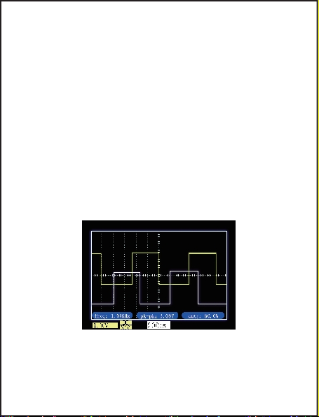
reference waveform of this unit does not support other
operations such as expansion or measurement. The
reference waveform is useful for a single-channel
oscilloscope. For example, when you want to compare
the driving waveforms of two Mos tubes, you can measure
the waveform of one Mos tube first, then lock the waveform
on the screen, and then move the probe to measure
the other. Mos tube, so two driving waveforms can be
displayed on the screen at the same time for easy
comparison. In the “running” state, click the “REF” button
to latch the current waveform. Click the button again
to delete the latched reference waveform from the screen.
8. Waveform screenshot: Click the "Save" button
in the keypad to capture the current screen and save
it. You can save up to 81 screenshots (9 pages in total,
09
9 per page). If you exceed 81, the oldest one will be
replaced. Delete unwanted images.
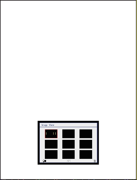
9. Browse screenshot: Long press the "Save"
button in the key panel to enter the Image View interface.
On this interface, click the button corresponding to
the "trash bin" icon to delete the waveform graph
selected by the red focus frame. Click the button (OK
key) corresponding to the "Zoom In / Zoom Out" icon
to zoom in the waveform selected by the red focus
frame. After zooming in, click any key to return to the
homepage. In the Image View homepage, move the
joystick left or right to move the red focus frame on
the current page. Turn the joystick up or down to “page
turn”. In the Image View interface, click the “Save”
button to return to the oscilloscope interface.
10
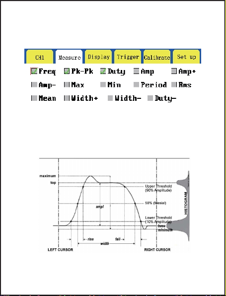
Frequency, peak-to-peak, positive duty cycle, amplitude,
positive amplitude, negative amplitude, maximum,
minimum, period, root mean square, average, positive
pulse width, negative pulse width, negative duty cycle
Introduction to measurement
options
11

No matter how pure gold is, it is impossible to achieve
100% purity. No perfect person, no perfect product,
but we have a team of responsible engineers.
This product supports firmware upgrades. We will
collect customer feedback and suggestions to upgrade
and optimize the product software. After that, we will
release our latest firmware in our official store.
(1)Click the "SEL" button immediately after power
on, the oscilloscope interface displays English letters
(2)U disk appears after connecting the USB cable,
paste the downloaded firmware to the U disk
(3)Eject USB, unplug USB cable, click “OK” button
to upgrade, shut down and restart after finishing.
Firmware upgrade
12
Upgrade method:

Learn about the following safety precautions to avoid
injury and prevent damage to this product or any products
connected to it. To avoid possible danger, be sure to use
this product as specified.
●Only authorized personnel should perform
maintenance procedures.
● Avoid fire and personal injury. Use the probe
correctly and make sure that the measured voltage does
not exceed the maximum withstand voltage.
● Connect the probe correctly. Before measuring
voltage greater than 40V, please switch the probe to
the x10 position.
● Do not operate the product if you suspect that
the product is malfunctioning. Should feedback with our
company and return to the factory for repair.
● Charge the battery correctly. The ideal charging
voltage is 5V, and the highest cannot be higher than
7V.
Safety Precautions
13

http://www.fnirsi.cn/
Table of contents
Other Fnirsi Test Equipment manuals

Fnirsi
Fnirsi DPOX180H User manual

Fnirsi
Fnirsi FNB28 User manual

Fnirsi
Fnirsi SG-003A User manual

Fnirsi
Fnirsi FNB48P User manual

Fnirsi
Fnirsi FNB48 User manual

Fnirsi
Fnirsi FNB38 User manual

Fnirsi
Fnirsi DSO-TC2 User manual

Fnirsi
Fnirsi DSO152 User manual

Fnirsi
Fnirsi DPOX180H User manual

Fnirsi
Fnirsi 1013D Instruction sheet


