Fnirsi FNB28 User manual

FNB28 user manual
(V1.0)

1
Table of Contents
一、Overview.................................................................................................................................................... 2
二、Pay attention to safety matters.................................................................................................................2
三、Appearance structure diagram................................................................................................................2
四、Technical index..........................................................................................................................................3
五、Function page operation instructions......................................................................................................3
1、Features page.............................................................................................................................................3
2、Capacity / Power consumption observation page..................................................................................... 4
3、Histogram page......................................................................................................................................... 4
4、Capacity / Power consumption table page................................................................................................ 5
5、Fast charge identification page..................................................................................................................6
6、Fast charge detection and trigger page......................................................................................................6
6.1 Fast charge protocol detection.............................................................................................................. 6
6.2 QC2.0 trigger........................................................................................................................................ 7
6.3 QC3.0 trigger........................................................................................................................................ 7
6.4 Huawei FCP trigger.............................................................................................................................. 8
6.5 Huawei SCP trigger.............................................................................................................................. 8
6.6 Samsung AFC trigger............................................................................................................................9
7、System information and settings page.....................................................................................................10
六、Upgrade firmware instructions..............................................................................................................12

2
一、Overview
FNB28 USB tester is a high-reliability, high-safety USB voltage and current detection meter
and mobile communication terminal fast charge trigger. With 0.96 inch TFT LCD display. Can be
used to measure the power supply or power consumption of products such as USB interfaces,
mobile phone chargers, U disks, etc .; can be used to measure mobile phone charging power, mobile
power input and output conditions; can be used to test the fast charging protocol of chargers.
This instruction manual includes relevant safety information, warning tips and solutions to
common abnormal conditions, please read the relevant content carefully and strictly observe all
warnings and precautions.
二、Pay attention to safety matters
1、Do not connect a power supply exceeding 24V to the tester.
2、FNB28 supports high power input (such as 20V * 5A = 100W).
3、When using high voltage and high power work, the temperature of the tester will rise.
Please be careful to prevent burns.
三、Appearance and structure diagram (see Figure 1)
1、USB-A 2.0 male connector
2、K1 button
3、K2 button
4、USB-A 2.0 female connector

3
图 1
四、Technical index
Accuracy: ±(a% of reading + number of words)
Index
Range
Resolution
Accuracy
Input voltage
4~24V
1mV
±(0.4%+3)
Input Current
0~5A
1mA
±(0.8%+3)
Input power
0~120W
0.1mW
±(1.0%+2)
Load Equivalent
Internal
Resistance
0~9999.9Ω
0.1mΩ
±(1.0%+2)
D + / D- voltage
0~3.3V
0.01V
±(1.0%+2)
Equipment
temperature
℃
1℃
±(1.2%+3)
℉
1℉
±(1.2%+4)
Capacity
0~99999.9mAh
0.1mAh
For reference
Energy used
0~9999.999Wh
0.001Wh
For reference
Record time
999 hours 59
minutes 59 seconds
1 second
10 seconds / hour
Equipment
runtime
999 hours 59
minutes 59 seconds
1 second
10 seconds / hour
五、Function page operation instructions
1、 Close-up page (see Figure 2)

4
Figure 2
Description
Only the four key parameters of voltage, current, power, and load equivalent impedance are
displayed. This page can change the display direction.
Instructions
(1) K1 key
Short press: Turn the page.
(2) K2 key
Short press: Turn the page.
Long press: switch screen display direction.
2、 Capacity / power consumption observation page (see Figure 3)
Figure 3
Description
FNB28 supports 4 sets of capacity / power consumption records.
XXX: XX: XX (white) indicates the capacity and power consumption recording time,
corresponding to 4 groups of capacity and power consumption, each has a recording time, and it
will not be lost when the power is off.
XXX: XX: XX (magenta) indicates the running time after power on, and reset after power on.
→Represents the direction of current.
Instructions

5
(1) K1 key
Short press: When set to manual recording, recording can be paused / started, and it is invalid
when set to automatic recording;
Long press: Clear the current group record data, including capacity, power consumption, and
record valid time;
(2) K2 key
Short press: page turning;
Long press: Switch to the histogram page (see Figure 4)
3、 Histogram page (see Figure 4)
Figure 4
Description
The capacity and power are expressed in two colors. The unit is shown below. The
measurement length is 65 units. The calculation formula is as follows:
Capacity: Red: x, unit: 2000mAh
Yellow: y, unit: 2000/65 = 30.76mAh
Capacity = 2000 * x + 30.76 * y (mAh)
Power: Blue: x, unit: 200Wh
Green: y, unit: 200/65 = 3.07Wh
Power = 200 * x + 3.07 * y (Wh)
Instructions
(1) K1 key
Short press: Clear window pops up; (cancel / confirm by clearing the current group by long
pressing K1 / K2)
Long press: return to the capacity / battery observation page (see Figure 3);
(2) K2 key

6
Short press: switch record group;
Long press: Switch to the capacity / power consumption table (see Figure 5).
4、 Capacity / power consumption table page (Figure 5)
Figure 5
Description
The data of each group can be compared directly based on the value.
Instructions
(1) K1 key
Short press: Clear window pops up; (cancel / confirm by clearing the current group by long
pressing K1 / K2)
Long press: return to the capacity / battery observation page (see Figure 3);
(2) K2 key
Short press: switch record group;
Long press: switch to histogram (see Figure 4).
5、Fast charge identification page (see Figure 6)
Figure 6
Description
This page is used to observe the current charging protocol, D + / D- voltage.
The list indicates the protocols that the current charging may be triggered, for reference only.
Instructions

7
(1) K1/K2 key
Short press: page turning.
6、Fast charge detection and trigger page (see Figure 7)
Figure 7
Description
Fast charge detection, fast charge trigger, long press K2 key to enter selection.
6.1 Fast charge protocol detection
After selecting the Protocol detection protocol detection, press and hold the K2 key for a long
time to pop up DANGEROUS !!! (see Figure 8). At this time, if you press and hold the K2 button
for a long time to enter the auto-detection fast charge protocol state; press and hold the K1 button to
cancel the detection。
After the test is completed (as shown in Figure 9), press and hold the K1 key to exit the test
interface; press and hold the K2 key to repeat the test steps and retest.
Figure 8
Figure 9
Note: Do not connect any electrical appliances during the detection process, otherwise the high
voltage triggered during the detection may burn the electrical appliances!

8
6.2 QC2.0 trigger
Select QC2.0, press and hold the K2 key to enter the QC2.0 trigger page (as shown in Figure
10), Fail Failure will display Trigger Failure!
Figure 10
Instructions
(1) K1 key
Short press: switch QC2.0 trigger voltage;
Long press: Exit the current page;
(2) K2 key
Short press: switch QC2.0 trigger voltage
6.3 QC3.0 trigger
Select QC3.0, press and hold the K2 key to enter the QC2.0 trigger page (as shown in Figure
11). Trigger Failure will display Trigger Failure!
Figure 11
Instructions
(1) K1 key
Short press: Decrease the trigger voltage of QC3.0; (step 200mV)
Long press: Exit the current page;
(2) OK key
Short press: raise QC3.0 trigger voltage. (Step 200mV)

9
6.4 Huawei FCP trigger
Select Huawei FCP, press and hold the K2 key to enter the Huawei FCP trigger page (as shown
in Figure 12). Trigger Failure will display Trigger Failure!
Figure 12
Instructions
(1) K1 key
Short press: switch FCP trigger voltage;
Long press:Exit the current page;
(2) K2 key
Short press: switch FCP trigger voltage.
6.5 Huawei SCP trigger
Select Huawei SCP, press and hold the K2 key to enter the Huawei SCP trigger page (as shown
in Figure 13). Trigger Failure will display Trigger Failure!
Figure 13
Instructions
(1) K1 key
Short press: reduce SCP trigger voltage;
Long press: Exit the current page; (Exit SCP trigger status at the same time)
(2) K2 key
Short press: Increase SCP trigger voltage.

10
6.6 Samsung AFC trigger
Select Samsung AFC, press and hold the K2 key to enter the Samsung AFC trigger page (as
shown in Figure 14). Trigger Failure will display Trigger Failure!
Figure 14
Instructions
(1) K1 key
Short press: Switch the AFC trigger voltage; (When the charger does not support the trigger
voltage, the voltage will return to 5V)
Long press: Exit the current page;
(2) K2 key
Short press: switch AFC trigger voltage. (When the charger does not support the trigger
voltage, the voltage will return to 5V)
7、System information and settings page (Figure 15)
Figure 15
Description
SN: XXXXXXXXXX represents the unique serial number of the product.
Run: XXXXXX indicates the number of times the device has been run.
VX.X indicates the current firmware version.
Instructions

11
(1) K1 key
(2) Short press: switch setting items;
(3) Long press: Exit the setting window;
(4) K2 key
Short press: switch setting items;
Long press: popup setting window
Setting item description
Screen display brightness setting, range 1-20 level.
K1 / K2 key: short press: adjust parameter.
Long press: cancel / confirm configuration.
Standby screen display brightness setting, ranging from 0-20 levels,
the backlight is turned off when standby is 0.
K1 / K2 key: short press: adjust parameter.
Long press: cancel / confirm configuration.
Enter standby time, ranging from 0-30 minutes. No standby when
OFF.
K1 / K2 key: short press: adjust parameter.
Long press: cancel / confirm configuration.
Automatic recording switch: ON: recording when the current exceeds
the threshold;OFF:电流阈值无效,由按键启停记录。
K1 / K2 key: short press: select.
Long press: Cancel / confirm configuration.
Recording time: limited capacity, power consumption recording time,
adjustable range: 0 ~ 8 hours.
When Unlimited, the capacity is recorded until the maximum.
K1 / K2 key: short press: adjust parameter.

12
Long press: cancel / confirm configuration.
Record keeping interval。
K1 / K2 key: short press: adjust parameter.
Long press: cancel / confirm configuration.
Current threshold: effective when the automatic recording switch is
ON, current ≥this value, recording capacity, power consumption.
K1 / K2 key: short press: adjust parameter.
Long press: cancel / confirm configuration.
Data transmission: ON / OFF
K1 / K2 key: short press: select.
Long press: cancel / confirm configuration.
Display temperature symbol: °F / ℃
K1 / K2 key: short press: select.
Long press: cancel / confirm configuration.
System language: EN / Chinese.
K1 / K2 key: short press: select.
Long press: cancel / confirm configuration.
Restore factory settings: This setting does not clear the recorded
values.
K1 / K2 key: short press: select.
Long press: cancel / confirm configuration.
13
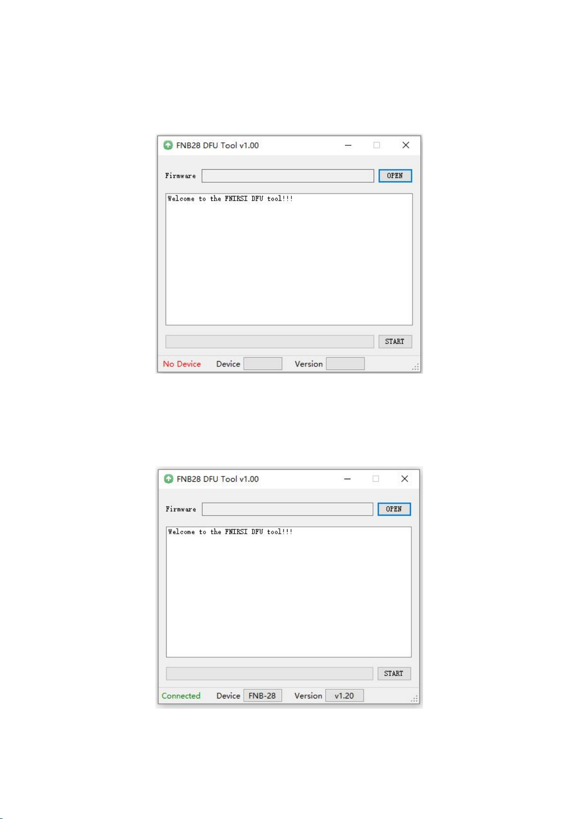
六、Upgrade firmware instructions
1、Open the FNIRSI USB Meter upgrade tool.
2、When FNB28 is in the shutdown state, press the OK key to access the
HID-USB interface, and it displays the connected, device model, and device
firmware version.
3、Click OPEN and choose to upgrade the firmware.

14
4、 Click START to start the firmware upgrade. After the upgrade is completed,
FNB28 will restart automatically.
Table of contents
Other Fnirsi Test Equipment manuals

Fnirsi
Fnirsi DSO152 User manual

Fnirsi
Fnirsi DSO-TC2 User manual

Fnirsi
Fnirsi FNC88 User manual

Fnirsi
Fnirsi DPOX180H User manual

Fnirsi
Fnirsi SG-003A User manual

Fnirsi
Fnirsi 1013D Instruction sheet

Fnirsi
Fnirsi FNB48P User manual

Fnirsi
Fnirsi FNB48P User manual

Fnirsi
Fnirsi FNB38 User manual

Fnirsi
Fnirsi FNB48 User manual


Popular Test Equipment manuals by other brands


Mityvac
Mityvac MV4530 user manual

Quantum Data
Quantum Data 606 quick start guide

IKONIX
IKONIX Associated Research HYAMP III Operation and service manual

IDEAL
IDEAL 61-796 instruction manual

Chauvin Arnoux
Chauvin Arnoux C.A 6470N TERCA 3 manual

SpectraCrop
SpectraCrop Plant Vitality and P-Tester user manual