Fnirsi FNB48P User manual

USB Fast charge tester
FNB48P

Catalog
1.Versions and Updates 01
2.Overview 01
3.Safety Precautions 01
5.Structure appearance 03
6.Technical index 04
4.0.1 Human-computer interaction 02
4.0.2 Voltage and Current 03
4.0.3 Fast charge trigger 02
4.0.4 Wire identification class 02
4.0.5 Miscellaneous 03
4.Performance description 02
7.0.1 Summary page 05
7.0.2 Record page 05
7.0.3 Fast charge recognition page 06
7.0.4 Curve display page 07
7.Main page 05

10.0.1 PD Listener 13
10.0.2 Read E-Marker cable 14
10.0.3 Read DASH cable 15
10.0.4 Analog DASH cable 15
10.0.5 Apple 2.4A acceleration 15
10.Charging tool 13
08
7.0.4 Wire resistance measurement page
8.0.1 Energy statistics list 08
8.0.2 Battery capacity calculation tool 09
8.Record function expansion 08
9.0.1 Fast charge protocol automatic detection 10
9.0.2 QC2.0 Trigger 10
9.0.3 QC3.0 Trigger 11
9.0.5 Huawei SCP trigger 11
9.0.4 Huawei FCP trigger 11
9.0.6 Samsung AFC trigger 11
9.0.7 PD Protocol trigger 11
9.0.8 PD PD Protocol conversion 12
9.0.9 VOOC/WARP Constant voltage trigger 12
9.0.10 SVOOC Trigger 12
9.Quick charge protocol trigger and detection menu 09

12.Upgrade firmware instructions 18
13.Production information 19
11.0.1 General 16
11.0.2 Record 17
11.0.3 Trigger related configuration 17
11.0.4 system 17
11.Setting menu 16

1.Versions and Updates
This product has many functions with frequent software and hardware updates, so, please
be aware that the manual may be updated at any time. Please get the latest information on
the official website.
2.Overview
The FNB48USB tester is a high-reliability, high-safety USB voltage and current detection
meter and a mobile communication terminal fast charging trigger. It has a 1.77-inch
TFTLCD display and integrated USB-A, Micro-USB, Type-C interfaces. Uses a dedicated
16-bit ADC, PD protocol physical chip. It can be used to measure the power supply or power
consumption of products such as USB interfaces, mobile phone chargers, U disks, etc.; it
can be used to measure mobile phone charging power and mobile power input and output
conditions; it can be used for charger fast charging protocol testing.
This instruction manual includes relevant safety information, warning tips and solutions to
common abnormal situations. Please read the relevant content carefully and strictly abide
by all warnings and precautions.
3.Safety Precautions
●Do not connect the monitoring interface to a power supply exceeding 24V.
●Do not connect the PC connection port to a power source exceeding 16V.
●Only one pair of monitoring interfaces (one input port, one output port) can work at the
same time. When there is a pair of monitoring interfaces working, it is forbidden to
connect to the equipment on other monitoring interfaces. (Except the PC connection
port, the PC port can be connected to an external power supply.)
●When using the fast charge trigger module, please do not connect equipment that
cannot withstand high voltage to any monitoring interface.
●After using the PD trigger/monitor/conversion/read E-Marker cable function, please turn
the PD communication switch in the lower right corner back to the OFF position.
●When working at high power,the temperature of the instrument rises.Please be careful to
prevent burns.
1

4.Performance description
1. 1.77 inch TFT-LCD screen
2. Multi-function switch
3.Touch switch
【 4.0.1 】 Human-computer interaction
1. The highest six-digit display of voltage, current and power, the highest resolution is
0.00001 (V/A/W).
2. Record the minimum, maximum and average values of voltage, current,and power
during operation.
3. 10 sets of switchable capacity, power, and time statistics.
4. 1 set of voltage and current curve records, maximum support 9 hours.
5.Support low-speed waveform (voltage, current, D+, D-) drawing, 2sps->100sps
sampling rate.
6. Support high-speed ripple (voltage, AC coupling) drawing, up to 3.2Msps sampling rate.
【 4.0.2】 Voltage and Current
【 4.0.4 】 Wire identification class
1. The internal resistance measurement of the
wire by the differential pressure method;
2. E-Marker Cable chip reading;
3. DASH Cable data reading;
●Do not charge the phone after the fast charge is triggered.The manufacturer is not
responsible if the phone is damaged by doing so.
1. QC2.0,QC3.0 trigger;
2. Huawei FCP,SCP trigger;
3. Samsung AFC trigger;
4. PD2.0/3.0 Trigger;
5. VOOC/WARP Trigger;
6. SuperVOOC Trigger;
7. The above protocols all support automatic monitoring;
8. MTK-PE automatic detection;
9. Support QC2.0->PD2.0 protocol conversion;
10. Support a maximum of 24 hours for a limited time
trigger, and automatically close the trigger when the
time comes.
【 4.0.3】 Fast charge trigger
2
【 4.0.5 】 Miscellaneous
1. Record of startup time
2. Onboard temperature measurement
3. Gravity sensor, automatically switch the display direction
4. PD monitor
5. Analog DASH cable
6. Apple 2.4A acceleration
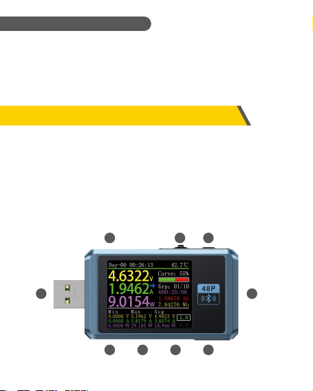
5.Structure appearance
1. Input monitoring port: USB-A, 5-PIN male;
2. Input monitoring port: TYPE-C, 24-PIN female socket;
3. Input monitoring port: Micro-USB, 5-PIN female socket;
4. Output monitoring port: TYPE-C, 24-PIN female socket;
5. PD communication switch;
6. Output monitoring port: USB-A, 5-PIN female;
7. Touch switch: BACK button;
8. Multi-function switches: left button, middle button, rightbutton;
9. PC connection port: Micro-USB, 5-PIN female socket.
1
2 3 4
6
789
5
3

6.Technical index
Accuracy: ±(a%(‰) reading + number of words)
Monitor voltage
Monitor current
Monitor power
D+/D- voltage
Capacity
Energy used
Cable resistance
Record time
Index
4~24V
0~6.5A
0~156W
0~9999.9Ω
0~3.3V
℃
℉
0~9999.99Ah
0~9999.99Wh
0~9999.9Ω
99d23h59min59s
99d23h59min59s
0.00001V
0.00001A
0.00001W
0.0001Ω
0.001V
1℃
1℉
0.00001Ah
0.00001Wh
0.0001Ω
1s
1s
Resolution
±(0.2‰+2)
±(0.5‰+2)
±(0.5‰+2)
±(0.5‰+2)
±(1.0%+2)
±(1.2%+3)
±(1.2%+4)
Accuracy
Range
Equipment
temperature
Equipmnt
running time
Load equivalent
internal resistance
4

7.Main page
●Except for special instructions, the left and right buttons switch pages/menus, the
middle button confirms, and the BACK button cancels/returns.
●On all pages, long press the BACK button to turn off the screen backlight.
●Starting from the lower left corner, the Min, Max, and Avg data are the minimum,
maximum and average values of voltage, current, and power respectively. Voltage,
current, and power can be distinguished according to the unit.
【 7.0.1 】 Summary page
Description
●The top row of data from left to right are boot
record time and onboard temperature respectively.
●The uppercase data on the left is voltage, current,
and power from top to bottom.
●The curve and progress bar on the right are the
remaining storage capacity of the voltage and
current curves.
●The groups on the right are from top to bottom,sta-
tistics group, current group capacity, power, time
value.
Description
●Only the three key parameters of voltage, current
and power are displayed, →indicates the direction
of current.
●This page can change the display direction.
Instructions
●Long press the left button: enter the setting menu.
●Click the middle button: switch to 6-bit resolution.
●Long press the middle button: When the setting
menu -> general -> gravity direction is recognized
as off, switch the screen direction.
【 7.0.2 】 Record page
5

【 7.0.3 】 Fast charge recognition page
●The dark blue below the trigger timing is the load resistance.
●The first column of the bottom white table is D+, D- voltage;the second column is the
current charging agreement that may be in progress;the third column is the status
bar. When the trigger timer starts, it will display RUN , and it will display STOP
when it stops,when the instrument does not trigger any fast charging protocol is
displayed as NONE , when a certain fast charging protocol has been triggered,
such as QC2.0, it is displayed as QC2.0 .
●There are two text boxes in the lower right corner, the first 1.0 from top to bottom is
the setting menu -> recording -> offline recording time, in hours, it is highlighted
when recording, otherwise it is grayed out; the second is the setting menu ->
record->energy statistics time, unit hour, when the value is 0.0, it means there is no
time limit for statistics.
Instructions
●Long press the left button: switch to the capacity/power consumption list (please
see the following instructions).
●Click the middle button: start/stop the voltage and current curve recording, it
cannot be started when the recording time is 0.
●Long press the middle button: restart the calculation of the minimum, maximum
and average values of voltage, current and power.
●Long press the right button: enter the battery capacity calculation tool (please see
the subsequent instructions).
Description
●The top row of data from left to right are boot
record time and onboard temperature respectively;
●The uppercase data on the left is voltage, current,
and power from top to bottom;
●The trigger time limit on the right is the setting
menu -> trigger-> trigger time value.
●Trigger timing is the timing of trigger time, when-
the timing reaches the trigger time limit, the meter
will stop triggering.
※Note: Please notice that after some protocols stop triggering, the charger will
6

【 7.0.4 】 Curve display page
7 28.00V 5.00A
5 20.00V 5.00A
Instructions
●Long press the left button: time base minus.
●Click the middle button: start/pause drawing the curve. (except in mode 3, it will
prompt whether to clear the curve).
●Long press the middle button: switch modes.
●Long press the right button: time base plus.
Low-speed voltage
and current curve
Low-speed D+Dcurve
Record offline curve High-speed voltage ripple
(AC coupling)
Instructions
●Long press the left button: prompt to enter the fast charge trigger module, if a
certain protocol has been triggered, it will prompt to release.
●Click the middle button: start/stop the trigger timing.
●Long press the middle button: prompt to clear the trigger timing.
●Long press the right button: enter the charging tool menu (please see the
subsequent instructions).
7

【 7.0.5 】 Wire resistance measurement page
【 8.0.1 】 Energy statistics list
Description
●FNB48 uses the differential pressure method to
measure the internal resistance of the cable, which
needs to be used with a constant current load.
Instructions
●Click the middle button: use the current voltage
and current value as the reference value.
Description
●In the record page (7.0.2), long press the left button
to enter.
●Each line in the list represents a group of
parameters, from left to right are group number,
capacity, energy, the selected group is displayed in
green, and the lower left corner is the selected
group Statistics time, the lower right corner is the
group number of the current statistics group.
8.Record function expansion
Instructions
●Click the middle button: switch to the selection group.
●Long press the middle button: select whether to clear the selected group.
Measurement procedure
●Connection mode: charger + FNB48 + constant current load (the current is adjusted
to about 0.5-1A), and record the reference value.
●Connection method: charger + cable + FNB48 + constant current load (the current is
adjusted to about 0.5-1A, which needs to be similar to the current when the
reference value is recorded),the system automatically calculates the internal
resistance of the cable.
8

9.Quick charge protocol trigger
and detection menu
【 8.0.2 】 Battery capacity calculation tool
Description
●In the record page (7.0.2), press and hold the right
button to enter.
●Select the statistics group,set battery voltage,
energy conversion efficiency, the battery capacity
can be calculated.Click the middle button to move
the green dot on the left between Group, battVol
and Conv Eff. Which item the green dot is in, you
can change the value of which item by clicking the
left/right button.Each item is explained below.
Description
●On the (7.0.3) fast charge recognition page, long
press the left button and confirm to enter.
●This meter supports QC2.0/QC3.0, HuaWeiFCP/SCP,
SamsungAFC trigger, VOOC/DASH constant
pressure mode, PD2.0/3.0 trigger,and QC2.0->PD2.0
protocol conversion.
●Group is the statistical group selected for calculation. This instrument can be
selected from 1-10 groups, statistical time, capacity,energy.It is displayed in order
from top to bottom on the right of the selected group number.
●BattVol is the battery voltage, the default is 3.7V, this parameter can be selected
from 3.0-5.0V, the actual value,please check the relevant information yourself.
●ConvEff is the energy conversion efficiency, the default is 90%.
●The red letter is the calculation result. If you want to get the result in mAh, please
convert it to x1000 by yourself.
9
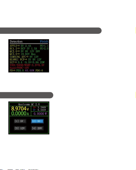
【 9.0.1 】 Fast charge protocol automatic detection
●In this mode,the meter tries to trigger various
protocols in turn,display the test results on the
screen,Red is not supported,Green is support.In
the process of testing,such as measuring PD
chargers.It is normal to restart and continue
testing.During the test, it is forbidden to connect
to any equipment at the back end.
●It does not respond to any key operation during
the test. If you want to exit during the test, please
unplug the meter directly.
【 9.0.2 】 QC2.0 Trigger
●In QC2.0 trigger mode, use the left and right keys
to select the trigger voltage, and click BACK to
return.
※Note:Once you enter the quick charge trigger/detection interface, all operations
must be carried out carefully.It is forbidden to access equipment that cannot
withstand high voltage.In the process of using this function,the author shall not be
liable for losses caused by misoperation.
●After the test is completed, click the middle button to start the test again; click the
BACK button to return to the previous page.
10

5.249 86V
0.755 26A 226mΩ
【 9.0.5 】 Huawei SCP trigger
The operation mode is the same as QC3.0 triggert
【 9.0.7 】 PD Protocol trigger
【 9.0.6 】 Samsung AFC trigger
The operation method is the same as QC2.0 trigger.
【 9.0.4 】 Huawei FCP trigger
The operation method is the same as QC2.0 trigger.
●Switch the PD communication switch to ON, enter
the PD protocol trigger mode.After exiting the PD
trigger, switch the PD communication switch to OFF.
●Take the picture as an example. The picture shows a
message sent by a charger.There are 6 gears in total,
of which gears 1, 2, 3, 4, and 5 are fixed voltage
gears.The sixth gear is the adjustable voltage gear
(PPS).
●When the left dot stays on Gear,the gear can be switched by the left and right keys.
When the gear is switched to PPS gear,then you can switch the step voltage by
clicking the middle button,after selecting the step voltage,through the left and right
keys (left minus right plus),decrease/increase voltage.
●In QC3.0 trigger mode,Use the left and right keys
to decrease/increase the trigger voltage,click
BACK to return.
●Press the left/right keys to quickly decrease/in-
crease the voltage.
【 9.0.3 】 QC3.0 Trigger
11

【 9.0.9 】 VOOC/WARP Constant voltage trigger
The operation method is the same as QC3.0 trigger.
【 9.0.10 】 SVOOC Trigger
SuperVOOC requires a load greater than 500mA on the back end to deceive, And
SuperVOOC only has a voltage of 10.5V.Therefore, you can only press BACK to return
to the page, and there is no other operation.
This function is used for only QC2.0 charger,But want to supply power to PD
appliances.
●Before use,switch the PD communication switch to ON,then enter the PD protocol
conversion mode, after entering,plug in PD appliances,you can perform PD fast
charge.
●In this mode,click the middle button and use the left and right buttons to change the
maximum power of packets sent by the PD.When changing power,be careful not to
exceed the charger power to avoid unnecessary damage.After changing the power,
you must click the middle button to confirm.
●Set 5V when no device is connected,avoid high-voltage damage to mobile phones
that do not support high-voltage when plugged in.
●QC2.0 only B type charger supports 20V trigger,so when the PD appliance requests
20V voltage,the tester will detect whether the charger successfully triggers
QC2.0-20V.If it does not reach 20V,The tester will cancel the 20V gear,and resend the
Caps broadcast.
●In addition,some PD appliances will change the D+ and D- voltages whencharging,-
Cause QC2.0 to trigger an exception,this type of PD appliances cannot usethis
function to charge.
【 9.0.8 】 PD Protocol conversion
12
●When using PD listener,Need to turn the PD
communication switch to ON,And use a power
supply not greater than 16V (usually 5V) and a
Micro-USB cable,Connect the PC online port,Provide
external power.
●Use the PD listener function, need 2 C-C cables,
connect the charger and PD electrical appliances
from the Type-CIN interface and Type-COUT interface
respectively. When the connection is normal and the
PD protocol triggered by the PD consumer is
captured, the page is represented as shown. When
the PD charger cannot be powered, because the C-C
cable has only one-sided CC, and the 2 CCs are not
connected, you can flip one of the C-C cable
connectors,to solve the problem.
Left column,You can select the message to be
viewed by left/key,Such as:
●Now select the message of 410x1882REQ<-. is the
message number,In this instrument, the larger the
message number, the newer the message.0x1882 is
the message header.REQ is the message type,
Represents this is a request (Request) message,The
request message (Request) is used to apply to the
charging head for the gear required for charging (for
example, it is 6 gears in this example,request one of
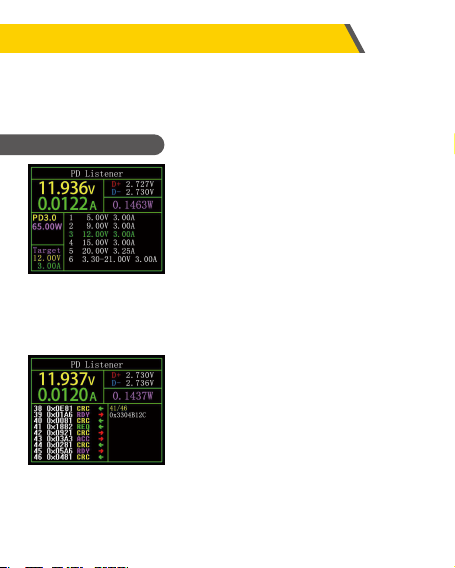
※The figure above,The charger is a
65W PD charging head, The curren
PD appliance chooses the third gear,
Trigger the target voltage 12V,
Maximum current 3A.
※Click the middle button,can switch
to the page of "View detailed
communication process",as shown.
【 10.0.1 】 PD Listener
●PD monitor ●Read the E-Marker cable
●Apple 2.4A acceleration●Analog DASH cable
●Read the DASH cable
10.Charging tool
On the (7.0.3) fast charge identification page, long- click the right button to enter
the charging tool menu. The functions are:
them). <- indicates the direction of data transmission.It means that this message was
sent by the PD consumer to the PD charging head.
13

●E-Marker cable refers to a cable with an E-Marker chip in the Type-C interface,If the
interface does not contain E-Marker chip.The packets from the PD charging head
cannot exceed 3A current,and only use the E-Marker cable to trigger the PD
protocol,the current can exceed 3A.
●When using PD listener,except that the Type-C interface cannot be used for power
supply,PC port, USB-A, Micro-USB interface can all be used for power supply.The PD
communication switch needs to be turned ON.
The two pictures above,the picture shows the parsed data,the second picture is the
original data,Users can consult the relevant information of the PD agreement by
themselves,do your own comparison.
【 10.0.2 】 Read E-Marker cable
●After entering this function, From
any Type-C interface, plug in the
cable. You can read the message,As
shown below.
●Click the middle button to switch
to the figure below.
●The voltage contained in the right column 0x3304B12C when sending a Request
message,Information such as current.
●In addition,under this interface,long press the left button,the data buffer can be
cleared. Long press the right button to quickly browse the messages.
Note:
●Open the settings menu -> trigger -> block PDCRC, you can turn off the monitoring
of CRC.
●For the meaning of various messages in the PD protocol, please refer to the relevant
information.
14

【 10.0.3 】 Read DASH cable
●Enter this function,plug in the DASH cable,you can
read the chip-related data,as shown below.
【 10.0.4 】 Analog DASH cable
This function is used without DASH cable
●The USB-A head of the DASH cable will have one more data pin than the ordinary
USB-A data cable.And one more chip,used to identify and start VOOC/WARP flash
charge.
●If the phone normally needs to use a USB-A->Type-C DASH cable,but there is no such
thread in hand,only FNB48 tester and a C-C cable,but want to trigger VOOC/WARP
flash charge.At this time, the function of simulating DASH cable can be started,and
use the C-C cable to connect to the phone, you can perform VOOC/WARP flash
charging.
※Note:Since this method does not use the original data cable for charging, the
charging power is largely affected by the C-C line.If the impedance of the C-C line is
high,then the charging power will be reduced a lot.
【 10.0.5 】 Apple 2.4A acceleration
When the Apple device detects that the charging head D+ and D- are 2.7V,to charge at
5V-2.4A,this function sets D+ and D- to 2.7V.
15

●Display brightness:Set the screen brightness, the adjustable range is 1-20.
●Standby brightness:Set the standby screen brightness,adjustable range 0-20 level,
when set to 0,enter the standby state and turn off the screen directly.
●Standby time:Set the standby time, the last time you operate the button to start
timing,reach the standby time,enter the standby state.
●Data transmission:After closing, you cannot connect to the computer through the
PC port.
●Temperature symbol:The onboard temperature can be displayed as °C/℉.
●Language:Currently only Chinese/English is supported. Due to the character size
problem, English will be displayed in the Chinese system, which is a normal
phenomenon.
●Current change wake up:Set the wake-up current,When the current change
exceeds the wake-up current,the meter changes from standby state to normal
working state.When set to 0, this function is turned off.
●Bluetooth switch:After closing, bluetooth data transmission is not possible.
●Gravity direction recognition:When opened,automatically switch page orientation,
After closing, unable to automatically switch the page reverse,but you can switch
the page direction by long pressing the middle button on the (7.0.1) simple page.
●Boot page:Turn on/off the boot page.
●Reset:Restore all settings except the recorded data.
11.Setting menu
●In the settings menu,left click and right click to select
menu options,click the middle button to enter/con-
firm the current option,click the BACK button to
return / cancel / exit the current option / menu.
【 11.0.1 】 General
Set up some general system configurations.
16
Other manuals for FNB48P
1
Table of contents
Other Fnirsi Test Equipment manuals

Fnirsi
Fnirsi SG-003A User manual

Fnirsi
Fnirsi FNB28 User manual

Fnirsi
Fnirsi FNC88 User manual

Fnirsi
Fnirsi FNB48 User manual

Fnirsi
Fnirsi FNIRSI-1C15 User manual

Fnirsi
Fnirsi FNB38 User manual

Fnirsi
Fnirsi DSO152 User manual

Fnirsi
Fnirsi FNB48P User manual

Fnirsi
Fnirsi 1013D Instruction sheet

Fnirsi
Fnirsi DPOX180H User manual


