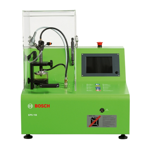
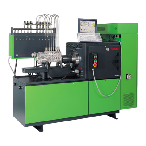
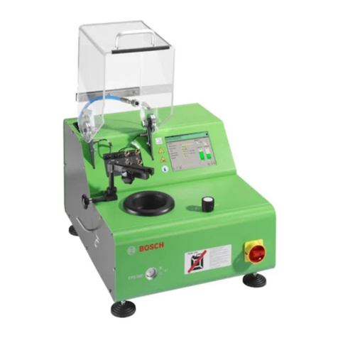
Bosch EPS 807 Setup guide

EPS 807 / 815
en
Repair instructions
Injection pump test bench

1 689 975 140 2013-07-01| Robert Bosch GmbH
2 | EPS 807 / 815 |en
Contents English
1. Symbols used 3
1.1 In the documentation 3
1.1.1 Warning notices -
Structure and meaning 3
1.1.2 Symbols – Designation and
explanation 3
1.2 On the product 3
1.3 Important notes 3
1.4 Safety instructions 4
1.4.1 Mains voltages and High voltages 4
1.4.2 Rotation 4
1.4.3 Dimensions and Weights 4
1.4.4 Pressures 4
1.4.5 Heat radiation 4
2. Assembly and Disassembly 5
2.1 Test-bench housing 5
2.2 Drive assembly 5
2.3 Test oil heating 6
2.4 Test oil circulation 6
2.4.1 Control valve Test Oil 7
2.4.2 Cut-off valve 7
2.5 Lubricating oil circulation 7
2.5.1 1. Generation 7
2.5.2 2. Generation 8
2.5.3 3. Generation 8
2.5.4 Lubricating oil-Control valve 9
2.6 Cabinet 9
2.6.1 Complete 9
2.6.2 Mounting panel 10
2.7 Economic transformer 11
2.8 Multiway tap with purge valve 11
3. Structure 12
3.1 Block diagram 12
3.1.1 EPS 815 up to date of manufacture
05-2002 12
3.1.2 EPS 815 from date of manufacture
06-2002 12
3.2 Injection pump test bench 13
3.3 Lubricating oil supply (Special accessories) 13
3.4 Switch case 13
4. Overview of possible fluctuations 14
5. Troubleshooting 15
6. Repair works 16
6.1 Change Flywheel 16
6.2 Replacing the drive motor 16
6.3 Change Test oil heating 17
6.3.1 Change Float switch 18
6.3.2 Change Temperature sensor 18
6.4 Readjusting the shut-off valve 19
6.5 Change Heating exchanger 19
6.6 Replacing the rotary encoder B1 20
6.6.1 Preparatory work 20
6.6.2 Removing the rotary encoder B31 20
6.6.3 Removing the rotary encoder B4 20
6.6.4 Removing the trigger wheel 20
6.6.5 Removing the flange with
rotary encoder 21
6.6.6 Removing the rotary encoder B1 21
6.6.7 Mounting the rotary encoder B1 21
6.6.8 Mounting the flange with
rotary encoder 22
6.6.9 Assembling the trigger wheel 22
6.6.10 Mounting the rotary encoder B4 22
6.6.11 Mounting the rotary encoder B31 23
7. Adjustment and Functional Test 24
7.1 Test the operating unit 24
7.1.1 Test tip switch elements 24
7.1.2 Test indicator lamps 24
7.1.3 Test emergency stop switch elements 24
7.2 Testing temperature sensors 24
7.3 Testing cooling proportional valve 24
7.4 Testing speed monitoring A5 (DZE) 25
7.4.1 Printed circuit board 1 688 400 009
(up to FD 12-2000) 25
7.4.2 Printed circuit board 1 688 400 251
(from FD 01-2001) 26
7.5 Sensor compensation on AMKASYN-Converter
(up to FD 05-2002) 27
7.5.1 Preparation 27
7.5.2 Performing sensor compensation 27
7.6 Sensor compensation on KU-Converter
(from FD 06-2002) 28
7.6.1 Preparation 28
7.6.2 Performing sensor compensation 28
8. Appendix 29

1 689 975 140 2013-07-01|Robert Bosch GmbH
Symbols used | EPS 807 / 815 | 3 en
1. Symbols used
1.1 In the documentation
1.1.1 Warning notices - Structure and meaning
Warning notices warn of dangers to the user or people in
the vicinity. Warning notices also indicate the consequenc-
es of the hazard as well as preventive action. Warning no-
tices have the following structure:
Warning
symbol
KEY WORD – Nature and source of hazard!
Consequences of hazard in the event of fail-
ure to observe action and information given.
¶Hazard prevention action and information.
The key word indicates the likelihood of occurrence and
the severity of the hazard in the event of non-observance:
Key word Probability of
occurrence
Severity of danger if in-
structions not observed
DANGER Immediate impend-
ing danger
Death or severe injury
WARNING Possible impending
danger
Death or severe injury
CAUTION Possible dangerous
situation
Minor injury
1.1.2 Symbols in this documentation
Symbol Designation Explanation
!Attention Warns about possible property damage.
iInformation Practical hints and other
useful information.
1.
2.
Multi-step
operation
Instruction consisting of several steps.
eOne-step
operation
Instruction consisting of one step.
Intermediate
result
An instruction produces a visible inter-
mediate result.
"Final result There is a visible final result on com-
pletion of the instruction.
1.2 On the product
!Observe all warning notices on products and ensure
they remain legible.
1.3 Important notes
Installation and/or repair work may only be performed
by trained and instructed Service personnel at Robert
Bosch GmbH or by organizations appointed to do such
work by Robert Bosch GmbH. If the devices are opened
or modified by unauthorized persons, then all warranty
claims will be rendered null and void.
Electrical systems and resources may only be put into
operation when in proper operating condition (for more
information, refer to Inspection and testing information
0108_084). This requirement is deemed to have been
fulfilled if after modification or repair (initial test) it has
been ascertained that requirements as specified by the
electrotechnical rules have been adhered to. To this
end, tests as under the type and scope of the measures
defined by the electrotechnical rules (e. in Germany BGV
A2) are to be conducted. The type and scope of tests are
specified in VDE 0701/0702 Section 1 within Germany.
The relevant national specifications are to be adhered to.
!Observe ESD handling instructions when working on
the device when it is open. The instructions are avail-
able in EDIS at 'Bosch Test Equipment\Inspection &
Testing A-Z\General notes\Safety'.

1 689 975 140 2013-07-01| Robert Bosch GmbH
4 | EPS 807 / 815 | Symbols useden
1.4 Safety instructions
1.4.1 Mains voltages and High voltages
Hazardous voltages occur in both the
network and the electrical system. If con-
tact is made with live parts, there is a risk
of electric shock from flashover voltages
caused by damaged insulation. That is why
the works on the electrical system or the
operating materials may be performed only
by electric’s specialists or by authorised
persons under guidance and supervision of
an electric’s specialist in accordance with
electrical regulations.
1.4.2 Rotation
Danger of injury!
When working in the area with rotating
parts, there is a danger of injury caused by
inattention of the operator in that he can be
grasped on the clothing.
¶Rotating parts must be masked off prop-
erly as far as possible.
1.4.3 Dimensions and Weights
If during the repair works bigger single
parts and assemblies are replaced, they
must be properly secured and attached on
the appropriate lifting devices so that they
can not cause any danger.
¶Use only both technically faultless lifting
devices and load sensor with adequate
portability!
¶Do not stay under suspended loads.
¶Assign the check of loads only to experi-
enced persons.
1.4.4 Pressures
Damage under high pressure can cause
leak of oil.
High hydraulic pressures occur during the
operation of the injection pump test benches.
¶Wear eye protective ware.
1.4.5 Heat radiation
Danger of burns!
The temperature on the surface of the brak-
ing resistance can achieve >60°C.
Open switch cabinet door can cause burn-
ing when touching the braking resistance on
the non-protected places.
¶Avoid works in this area, in case they can
not be evaded, allow the braking resis-
tance to cool down first.

1 689 975 140 2013-07-01|Robert Bosch GmbH
Assembly and Disassembly | EPS 807 / 815 | 5 en
2. Assembly and Disassembly
2.1 Test-bench housing
458719/1P
Fig. 1: Test-bench housing
2.2 Drive assembly
458722/2P
Fig. 2: Drive assembly

1 689 975 140 2013-07-01| Robert Bosch GmbH
6 | EPS 807 / 815 | Assembly and Disassemblyen
2.3 Test oil heating
4587231P
Fig. 3: Test oil heating
2.4 Test oil circulation
458720/3P
Fig. 4: Test oil circulation

1 689 975 140 2013-07-01|Robert Bosch GmbH
Assembly and Disassembly | EPS 807 / 815 | 7 en
2.4.1 Control valve Test Oil
458729-14_Pal
Fig. 5: Control valve Test Oil
2.4.2 Cut-off valve
458729-15_P
al
Fig. 6: Cut-off valve
2.5 Lubricating oil circulation
2.5.1 1. Generation
458729-16_Pal
Fig. 7: Lubricating oil circulation
458729-17_Pal
Fig. 8: Test Oil tank

1 689 975 140 2013-07-01| Robert Bosch GmbH
8 | EPS 807 / 815 | Assembly and Disassemblyen
2.5.2 2. Generation
458729-18_Pal
Fig. 9: Lubricating oil circulation
458729-19_Pal
Fig. 10: Test Oil tank
2.5.3 3. Generation
458729-20_Pal
Fig. 11: Lubricating oil circulation
458729-21_Pal
Fig. 12: Test Oil tank

1 689 975 140 2013-07-01|Robert Bosch GmbH
Assembly and Disassembly | EPS 807 / 815 | 9 en
2.5.4 Lubricating oil-Control valve
458729-22_Pal
Fig. 13: Lubricating oil-Control valve
2.6 Cabinet
2.6.1 Complete
458729/6P
1
2 3 4 AZR
Fig. 14: Cabinet up to FD 05-2002
HAUPTSCHALTER
MAIN SWITCH
458729-10_Pa
AMK
DANGER
Fig. 15: Cabinet from FD 06-2002

1 689 975 140 2013-07-01| Robert Bosch GmbH
10 | EPS 807 / 815 | Assembly and Disassemblyen
2.6.2 Mounting panel
458729-11_Pal
Fig. 16: Mounting panel up to FD 05-2002
458729-12_Pal
Fig. 17: Mounting panel from FD 06-2002

1 689 975 140 2013-07-01|Robert Bosch GmbH
Assembly and Disassembly | EPS 807 / 815 | 11 en
2.7 Economic transformer
458738/1P
Fig. 18: Economic transformer
2.8 Multiway tap with purge valve
458733P
Fig. 19: Multiway tap up to FD 05-2000
458729-13_Pal
Fig. 20: Multiway tap 1 687 010 126 from FD 06-2000

1 689 975 140 2013-07-01| Robert Bosch GmbH
12 | EPS 807 / 815 | Structureen
3. Structure
3.1 Block diagram
3.1.1 EPS 815 up to date of manufacture 05-2002
458741-17_Pal
Fig. 21: Block diagram
3.1.2 EPS 815 from date of manufacture 06-2002
458741-17_Pal
Fig. 22: Block diagram

1 689 975 140 2013-07-01|Robert Bosch GmbH
Structure | EPS 807 / 815 | 13 en
3.2 Injection pump test bench
Code Designation Function
B1 Speed sensor Speed sensing
B2 Limit switch Limit switch test oil tank
B3 Sensor Temperature sensor test oil tank
(long)
B4 Speed sensor Speed sensing (Speed monitoring)
B5 Sensor Temperature sensor Inflow
E1 Heating element Test oil heating
E2 Heating element Test oil heating
E3 Heating element Test oil heating
M1 Three-phase motor Drive
M2 Three-phase motor Test oil supply
Y3 Control valve Cooling water regulation
3.3 Lubricating oil supply (Special acces-
sories)
Code Designation Function
M3 Three-phase motor Lubricating oil supply
Q3 Engine protective
circuit
Engine protection Lubricating oil
supply
S8 Pressure tip switch Lubricating oil engine ON
S9 Pressure tip switch Lubricating oil engine OFF
3.4 Switch case
Code Designation Function
A1 Electric module supply Mains module AN 10F
A2 Monitor unit Central module AZ 10
A3 Frequency converter Change straightening module
AW 14/24
A4 Populated PC board Computer card AZ R01
A5 Populated PC board Speed module DZE 800
F2 G-fusible link Safety fuse Secondary wind-
ing 24V/5AT on T2
F3 G-fusible link Safety fuse for secondary
winding +4V/5AT on T2
F4 G-fusible link Safety fuse Secondary wind-
ing 20V/2,5AT on T2
F5 G-fusible link Safety fuse Secondary wind-
ing 28V/2AT on T2
F6 Overload circuit breaker Safety fuse for Stop / Start
12V/7A
F7 Overload circuit breaker Safety fuse for Stop / Start
24V/7A
F8 G-fusible link Safety fuse Secondary wind-
ing 230V/2,5AT on T3
F9 Overload circuit breaker Safety fuse for Test oil heat-
ing
F10 Overload circuit breaker Safety fuse for primary wind-
ing on T2
F11 Overload circuit breaker Safety fuse for primary wind-
ing on T3
F12 Overload circuit breaker Safety fuse for primary wind-
ing on T4
F13 G-fusible link Safety fuse Secondary wind-
ing 100V/5AT on T4
H1 Detecting lamp Converter "ON"
Code Designation Function
H2 Detecting lamp Drive motor "ON"
H3 Detecting lamp Program Test oil heating "ON"
H4 Detecting lamp Lubricating oil engine "ON"
K1 Contactor Program Test oil heating
K2 Contactor Heating protection
Q1 Main switch Mains switch-on
Q2 Engine circuit breaker Engine protector Test oil sup-
ply
S1 Emergency stop switch Emergency shutoff
S2 Pressure tip switch Converter "ON"
S3 Pressure tip switch Converter "OFF"
S4 Pressure tip switch Drive motor "ON"
S5 Pressure tip switch Drive motor "OFF"
S6 Pressure tip switch Program Test oil heating "ON"
S7 Pressure tip switch Program Test oil heating
"OFF"
S8 Pressure tip switch Lubricating oil engine "ON"
S9 Pressure tip switch Lubricating oil engine "OFF"
T2 Control transformer Voltage supply MGT and KMA
T3 Control transformer Voltage supply 230V Socket
T4 Control transformer Voltage supply. 100V in Japa-
nese version
V1 Si Rectifier Voltage supply for Stop / start
magnet
V2 Si Rectifier Voltage supply for Stop / start
magnet
X2 Plug connection Measuring system MGT800 or
KMA 802
X3 Multi-pin socket Connection for PC, screen
and timing lamp
X4 Terminal Stop / Starting magnet -
X5 Terminal Stop / Starting magnet +12V
X6 Terminal Stop / Starting magnet +24V
X7 Plug connection Computer interface drive

1 689 975 140 2013-07-01| Robert Bosch GmbH
14 | EPS 807 / 815 | Overview of possible fluctuationsen
4. Overview of possible
fluctuations
EPS815
EPS815
min
KMA 802
BOSCH
1 2 4 5 6 7 8 9 10
11
12
BOSCH
MGT 824
KMA 822
EPS815
KMA 802
BOSCH
1 2 4 5 6 7 8 9 10
11
12
458726P
BOSCH
Fig. 23: Overview

1 689 975 140 2013-07-01|Robert Bosch GmbH
Troubleshooting | EPS 807 / 815 | 15 en
5. Troubleshooting
Kurzzeichen Benennung Funktion Besondere Hinweise
Tip switch S2 (UE)
without efficiency
(Interruption
drive-end circle)
230 VAC supply is not available
(measuring on A1_X03 Terminals
LL0 and LL1)
Checking transformer T3,
Safety fuse F11, F8
(measuring on Kl100/101)
Error A2 (AZ module) Using control unit of the measuring system
or AMK control unit Error diagnostics
Keep emergency tip switch
S1.17/18 depressed
Remove emergency stop switch S1
DZE/A5 - Stop
(PCB 1 688 400 009: LED V59
lits and LED V78 blinks
or
PCB 1 688 400 251: LED V29 lits
and LED V23 blinks)
Interpret DZE error message
(Interface A5_X8 - A4_X77 is broken, inter-
face A5_X10 - measuring system is bro-
ken, speed recess is not switched on, po-
sition recess is not kept, unequal running
direction)
A5 / Software is damaged
(PCB 1 688 400 009: LED V59
lits and LED V78 is off
or
PCB 1 688 400 251: LED V29 lits
and LED V23 is off)
Reinstall software for DZE/A5, if not suc-
cessful replace LP
Hardware interruption in the
drive-end circle
Check the following cables:
A2_X25 - A5_X11 (signals ES1 - ES2),
A5_X11 (signals S1.21-S1.22, switch com-
ponent S1.2 of control unit)
Precaution!
If the main switch Q1 is on
these cables lead 230V !
Interruption of the
emergency-off circle
(there is 24 VAC be-
tween A5_X1.3 and
A5_X1.2)
Transformer T2,
Safety fuse F2, F10
Check F10 /engage,
check F2 (F2 is mounted onto the terminal
strip Transformer T2)
If transformer is in good condi-
tion and safety fuses are secure
there is
24 VACbetween Kl160 and
Kl161
Emergency off S1.11-S1.12,
Cable Control unit
Remove emergency switch-off S1 If the switch and cable are in
good condition there is 24VAC
between Kl160 and Kl165
Float switch,
Tank temperature > 70°C
Fill up test oil or let temperature cool
down
In order to correct the mistake
EPS must be switched-on dead
during shutoff on account of
tank >70°C .
There is 24 VAC between Kl160
and 166!
Engine circuit breaker Q2
has activated (Secondary switch
1.13-1.14)
Engage Q2, check the set release current
(1.8A), if necessary check test engine
DZE / Connecting
cable is damaged
Cable A5_X2 - A2_X30/31 is dam-
aged
Check cable /
see Item 7.1
After printing of S2 (UE) there
is approx. 24 VDC on A2_X31
(UE and 0V)!
If cable is in good condition.:
Check A5 (LP DZE)
see Item 7.2

1 689 975 140 2013-07-01| Robert Bosch GmbH
16 | EPS 807 / 815 | Repair worksen
6. Repair works
6.1 Change Flywheel
!Bosch does not operate the lifting and removal tool.
4
3
1
2
458741/5
Fig. 24: Lifting and removal tool for the flywheel
1 Eye bolt DIN 580-M12
2 Hexagon nut M12
3 Hexagon screw M10 x 35-8.8
4 Hexagon screw M16 x 50-8.8
1
2
458741/4
Fig. 25: Overview of flywheel with drive motor
1 Centering piece
2 Intermediate flange
Disassembly Flywheel:
1. Remove the inner hexagon screw from adapter (Fig.
25, Pos. 1).
2. Remove the adapter (Fig. 25, Pos. 1).
3. Remove the inner hexagon screw (7x) from interme-
diate flange (Fig. 25, Pos. 2).
4. Deactivate intermediate flange (Fig. 25, Pos. 2) or
unseat using two hexagon screws M10 or M12 from
flywheel.
5. Fix flywheel (weight 62 Kg) using the applicable lift-
ing gear (see Fig. 24).
6. Release flywheel from the cone by beating slightly
with a rubber hammer and lift it off.
Montage:
¶The assembly is carried out in reciprocal succession
and comply with Instructions in Item 6.2.
6.2 Replacing the drive motor
458741-06_Pal
1
2
3
4
5
6
7
8
9
Fig. 26: Overview of drive motor
Disassembly:
1. Remove the flywheel (see section 6.1).
2. Remove storage sheets from oil tray.
3. Put the wooden strip under the clamping rail (for
support).
4. Remove inner hexagon screw (Fig. 26, Pos. 1) (4x)
between brackets (console) and engine flange.
2
1
3
458741-07_Pal
Fig. 27: Securing the clamping rail
5. Loosen hexagon screw (Fig. 27, Pos. 1) (2x) between
supporting frame and rubber-bonded metal.

1 689 975 140 2013-07-01|Robert Bosch GmbH
Repair works | EPS 807 / 815 | 17 en
6. Unscrew the hexagon nut (Fig. 3, Pos. 7) (2x) to the
end of the threaded bolt.
7. Remove the hexagon nut (Fig. 3, Pos. 6) (2x).
8. Tip the control cabinet.
9. Remove the oval head screw securing the front panel
(Fig. 3, Pos. 2) (4x) on the mounting frame (Fig. 3,
Pos. 4).
10. Dump front mask (Fig. 26, Pos. 2).
11. Remove hexagon screws (Fig. 26, Pos. 9) (4x).
12. Lift up supporting frame (Fig. 26, Pos. 4).
13. Remove hexagon screws (Fig. 26, Pos. 8) (8x) on
motor base.
14. Attach the drive motor (Fig. 3, Pos. 3) to the eye
bolts.
15. Lift the drive motor (weight 350 kg) from the sup-
port frame using the hoist.
Assembly:
¶Reciprocal succession in relation to disassembly
!When performing assembly of the brackets (console)
on the three-phase motor the brackets (console)
must be picked up onto the aligning pin Pos. 9 and
lay on the both cylindrical pins Pos. 10. The inner
hexagon screws Pos. 7 must be tightened with one
tightening torque of 80Nm.
!During the assembly of the flywheel and the inter-
mediate flange the tightening torque for the inner
hexagon screws amounts to 70+5Nm
!The assembly of the adapter is carried out with
70+5Nm.
!After the assembly of the flywheel it must be tested
for true running and face strike, in which here is only
max 0,05 mm permitted.
!Align the drive motor and clamping rail unit centrally
on the support frame.
6.3 Change Test oil heating
1
3
7
6
4
5
2
458741/8
Fig. 28: Test oil heater with connecting cable
!When lifting the fastening panel (Fig. 28, Pos. 7) and
demounting or mounting the heating elements
(Fig. 28, Pos. 1) ensure that the float switch (Fig. 28,
Pos. 6) and the temperature sensor (Fig. 28, Pos. 3)
are not damaged for it can cause faulty measurement
or failure of heater controls.
Disassembly:
1. Disconnect electrical connecting cable from the
damaged heating element (Fig. 28, Pos. 1) in the
switch cabinet.
2. Pull connecting cable through the cable screwing.
3. Remove hexagon screw (Fig. 28, Pos. 4).
4. Lift off fastening panel (Fig. 28, Pos. 7).
5. Remove inner hexagon screw (Fig. 28, Pos. 5).
6. Pull down heating elements.
Assembly:
¶The assembly is carried out in reciprocal succession.

1 689 975 140 2013-07-01| Robert Bosch GmbH
18 | EPS 807 / 815 | Repair worksen
6.3.1 Change Float switch
458741/9
Fig. 29: Float switch with connecting cable
!It is not necessary to remove the fastening panel
while demouning the float switch. During the disas-
sembly ensure that the brass sleeve is not concealed
or damaged, otherwise it can cause the failure of the
float switch.
Disassembly:
1. Pull plug from float switch.
2. Remove inner hexagon screws (4x).
3. Pull up float switch.
Assembly:
1. Launch float switch in fastening panel.
2. Align float switch with cable port to the back.
3. Attach float switch with inner hexagon screw (4x).
4. Slip on plug.
6.3.2 Change Temperature sensor
458741/10
Fig. 30: Temperature sensor with connecting cable
!When lifting the fastening panel (Fig. 28, Pos. 7) and
demounting or mounting of the temperature sensor
ensure that the temperature sensor is not damaged,
otherwise it can cause faulty measurements or the
failure of heater controls.
Disassembly:
1. Pull off electric connecting cable of the damaged
temperature sensor (BNC plug).
2. Remove hexagon screws (Fig. 28, Pos. 4).
3. Lift off fastening panel (Fig. 28, Pos. 7).
4. Remove hexagon nuts.
5. Pull up temperature sensor.
Assembly:
¶The assembly is carried out in reciprocal succession.

1 689 975 140 2013-07-01|Robert Bosch GmbH
Repair works | EPS 807 / 815 | 19 en
6.5 Change Heating exchanger
458741-11_Pal
1
2
34
Fig. 31: Heat exchanger with valve
1 Cooling water outlet
2 Cooling water inlet
3 Test oil inlet
4 Test oil outlet
!When connecting the cool water and test oil cables
ensure that they are joint in the counter current.
Should this regulation stayed unnoticed it can cause
decreased cooling result.
Disassembly:
1. Demount cool water hose lines
2. Demount test oil hose lines
3. Screw out heating exchanger with fastening panel
completely
Assembly:
¶Reciprocal succession in relation to disassembly
6.4 Readjusting the shut-off valve
!When mounting the shut-off valve ensure that the
pressure lines are not mistaken for pressure testers
(Danger of pressure testers destruction. See also
section 2.4).
Aligning the shut-off valve:
1. Release counter nut.
2. Screw in threaded pin to half.
3. Tighten counter nuts.
4. Switch on injection pump test bench.
5. Turn test oil control valve slowly to the left until the
shut-off closing.
6. Observe the lock point.
7. Release counter nuts.
8. If the indicated pressure is over 6 bars screw out
threaded pin. If the indicated pressure is lower than
6 bars screw in threaded pin.
9. Tighten counter nuts.

1 689 975 140 2013-07-01| Robert Bosch GmbH
20 | EPS 807 / 815 | Repair worksen
6.6 Replacing the rotary encoder B1
iThe following description only applies to the drive
motor 1687220905.
6.6.1 Preparatory work
1. Turn off the EPS 815 at the master switch.
2. Disconnect the EPS 815 from unit from the mains
and secure to prevent renewed switch-on.
3. Remove the component connected to the flywheel.
4. Remove the side cover (Fig. 32, Pos.1) on both
sides.
HAUPTSCHALTER
MAIN SWITCH
458772-1
1
Fig. 32: Removing the side panel
6.6.2 Removing the rotary encoder B31
iThe rotary encoder B31 is not contained as standard
in the EPS 815 and is retrofitted in conjunction with
the test sets VPM844 and CAM847. In it's as-deliv-
ered condition, the EPS 815 has a cover in place of
the rotary encoder B31.
1. Loosen the collet chuck. To do so, unscrew the hexa-
gon socket head bolt (Fig. 33, Pos. 5).
2. Remove the hexagon socket head bolt (Fig. 33,
Pos. 4).
3. Remove the rotary encoder B31 (Fig. 33, Pos. 3) or
the cover (Fig. 33, Pos. 2).
6.6.3 Removing the rotary encoder B4
1. Remove the connecting cable from rotary encoder
B4 (Fig. 33, Pos. 1).
2. Remove the rotary encoder B4 (Fig. 33, Pos. 1). To
do so, loosen the lock nut and then unscrew the
rotary encoderB4.
1
234
5
458741-19_Pal
Fig. 33: Drive motor with rotary encoder B31
6.6.4 Removing the trigger wheel
1. Remove the hexagon socket head bolt (Fig. 34,
Pos. 4).
2. Remove the housing flange (Fig. 34, Pos. 1).
3. Remove the retaining ring (Fig. 34, Pos. 3) with
retaining ring pliers.
4. Remove the trigger wheel (Fig. 34, Pos. 2) from the
shaft. Do not lose the feather key in the shaft.
1234
458741-20_Pal
Fig. 34: Removing the trigger wheel
Other manuals for EPS 807
1
This manual suits for next models
1
Table of contents
Other Bosch Test Equipment manuals

Bosch
Bosch BAT 115 User manual

Bosch
Bosch CH-47976 User manual

Bosch
Bosch MOT 240 User manual

Bosch
Bosch CRS 845 Setup guide

Bosch
Bosch EPS 807 User manual

Bosch
Bosch KTS 340 User manual

Bosch
Bosch SCT 815 User manual

Bosch
Bosch EPS 118 User manual

Bosch
Bosch KTS 200 User manual

Bosch
Bosch KTS 200 User manual

Bosch
Bosch EPS 205 User manual

Bosch
Bosch KTS 200 User manual

Bosch
Bosch RG8.0 User manual

Bosch
Bosch CRI 848H User manual

Bosch
Bosch FSA 500 User manual

Bosch
Bosch EMMIT User manual

Bosch
Bosch BEA 055 User manual

Bosch
Bosch SDL 43 Series Technical specifications

Bosch
Bosch EFEP 60H User manual

Bosch
Bosch EPS 200 User manual